

Input Devices:
In this Tenth week of Fab Academy, we had room to explore various Input Devices like the Sensors.
Objective:
1. Group assignment:(Input Devices)
Details here.This week is having the following Objectives for the Group-
- Probe an input device(s)'s analog and digital signals
- Document your work (in a group or individually)
2. Individual assignment:(Input Devices)
Measure something: add a sensor to a microcontroller board that you have designed and read it.
Learning Outcomes:
Demonstrate workflows used in sensing something with input device(s) and MCU board
Checklist:
Linked to the group assignment page ✔
Documented what you learned from interfacing an input device(s) to microcontroller and how the physical property relates to the measured results ✔
Documented your design and fabrication process or linked to previous examples. ✔
Explained the programming process/es you used ✔
Explained problems and how you fixed them ✔
Included original design files and source code ✔
Included a ‘hero shot/video’ of your board ✔
Opening Quotes:
- “Reality exists in the mind of each. The senses are input devices for incoming data.” ― Toba Beta
Working of Input Devices / Sensors
1. Group assignment: Details here.
For this week, we had to understand the working principles of various Sensors, Probe them and take the readings on the DSO (Digital Storage Oscilloscope) / CRO (Cathode Ray Oscilloscope).
We decided to test the Sensors that we will be using for our final projects. So, Anand and Rahul tested the BME 280 (Temperature Humidity and Pressure) Sensor, BH 1750 (Light) Sensor, Mohit tested the Hall effect sensor, Vijay tested the PT 100 Temperature sensor and I tested the Load cell with HX711 module and RFID - MFRC522 Sensor.
2. Individual assignment:
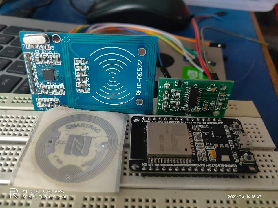
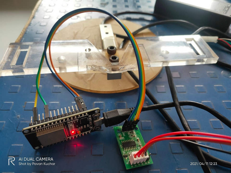
ESP32D + MFRC 522 + HX 711 Module
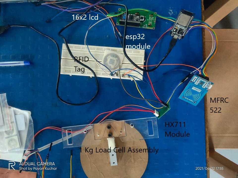
ESP32D + MFRC 522 + HX 711 Module and LCD display connected for Testing:
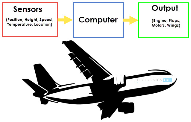
Input Devices:An input device is a peripheral used to provide data and control signals to a computer. Input devices allow us to enter raw data for processing. Input devices allow us to enter raw data for processing.
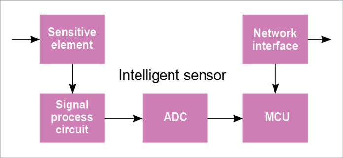
The term “input device” in the definition of a Sensor means that it is part of a bigger system which provides input to a main control system (like a Processor or a Microcontroller).
Another unique definition of a Sensor is as follows: It is a device that converts signals from one energy domain to electrical domain. The definition of the Sensor can be better understood if we take an example in to consideration.
Working of Input Devices / Sensors
Various Types of Input Devices are:
| For Computer / Laptop | For MicroControllers and MicroProcessors |
|---|---|
| Mouse | Magnetic Field |
| Trackball | Motion |
| Keyboard | Temperature |
| Microphone | Sound |
| Digital Camera | Moisture |
| Scanners-2D and 3D | Pressure |
| Touch Screens | Gas |
| Barcodes | Light |
| QR Codes | pH |
| Graphics | Load |
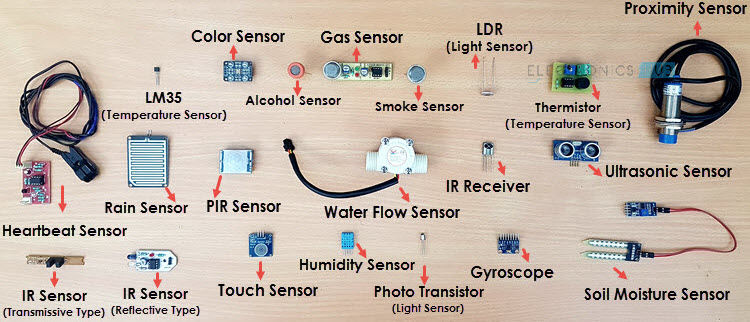
There are many Input Devices used in Electronics for the IoT projects. MYTHINGS IoT Sensor is a hardware independent, small-footprint and power-optimized library of code, featuring the MIOTY (TS-UNB) low-power wide area network protocol. Few others are - Proximity Sensor, Accelerometer, Gyroscope, IR Sensor (Infrared Sensor), Ultrasonic Sensor, Smoke and Alcohol Sensor, Touch Sensor, Color Sensor, Humidity Sensor, Position Sensor, Magnetic Sensor (Hall Effect Sensor), Microphone (Sound Sensor), Tilt Sensor, Flow and Level Sensor, PIR Sensor, Touch Sensor, Strain and Weight Sensor
Probing: A test probe is a physical device used to connect electronic test equipment to a device under test (DUT). To probe means to measure, observe or monitor signals with test probes.
Various Sensors
Sensor/Detectors/Transducers are electrical, opto-electrical, or electronic devices composed of specialty electronics or otherwise sensitive materials, for determining if there is a presence of a particular entity or function. Many types of sensors, detectors, and transducers are available including those for detecting a physical presence such as flame, metals, leaks, levels, or gas and chemicals, among others. Some are designed to sense physical properties such as temperature, pressure, or radiation, while others can detect motion or proximity. They operate in a variety of manners depending on the application and may include electromagnetic fields, or optics, among others. Many applications over a wide range of industries use sensors, detectors, and transducers of many kinds to test, measure, and control various processes and machine functions. With the advent of the Internet of Things (IoT), the need for sensors as a primary tool to provide enhanced automation is increasing.
Classification of Sensors:All these sensors are used for measuring one of the physical properties like Temperature, Resistance, Capacitance, Conduction, Heat Transfer etc.
- Active and Passive: Active Sensors are those which require an external excitation signal or a power signal. Passive Sensors, on the other hand, do not require any external power signal and directly generates output response.
- Means of Detection:Electric, Biological, Chemical, Radioactive etc.
- Conversion Phenomenon:Photoelectric, Thermoelectric, Electrochemical, Electromagnetic, Thermooptic, etc.
- Analog and Digital:nalog Sensors produce an analog output i.e., a continuous output signal (usually voltage but sometimes other quantities like Resistance etc.) with respect to the quantity being measured.
Digital Sensors, in contrast to Analog Sensors, work with discrete or digital data. The data in digital sensors, which is used for conversion and transmission, is digital in nature.
For this Assignment, I decided to test and explore the various Sensors that I may use in the Final Project. This is how the work would be done and I will get more insights about the Sensors and their working Principles.
I am pursuing Project on Smart Goat Weight Measurement and Monitoring System. For this, I will apply RFID Tags on the Goats for their Identification. This would also help in maintaining their records of Weight.
I would build a Weighing Machine for thr Goats. Proximity Sensors would be used for automatic door operations.
Load Cell would be used for the Weighing Balance. The weight thus taken would be then displayed and sent to the Cloud for datalog and analysis of the FCR (Food Conversion Ratio) which will help in finding the Profitability and maintaing health and weight record of the Goats.
LCD display would be used for displaying the Weight. It would be a part of the Output Devices week's assignment.
I will use ESP32 Wroom 32D Microcontroller Board for the Project.
The flow of this Assignment is as follows:
- Introduction to Load Cell Sensor
- Introduction to RFID Sensor
- Introduction to Proximity Sensor
- Introduction to Espressif ESP32 Wroom 32D
- Designing the ESP32 Board
- Milling the Board
- Stuffing and Soldering the Components
- Probing the Sensors / Input Devices:to measure, observe or monitor signals with test probes
- Load Cell: Adding Libraries, Calibration, Testing Sketch / Programs
- RFID Sensor:
- Summary:
- Videos and Downloads
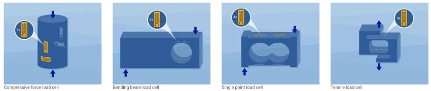
Load Cell Sensor:
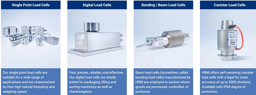
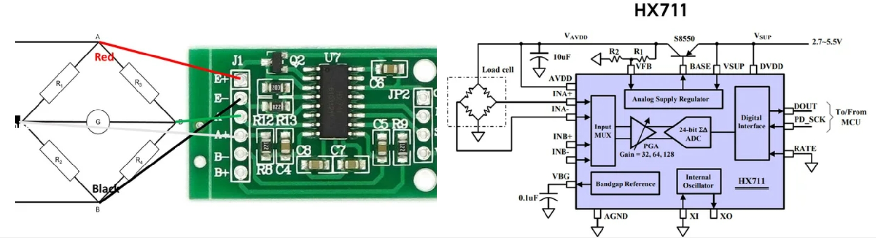
The load cell is able to measure the electrical resistance that changes in response to the strain (e.g. pressure or force) applied to the load cell. Load cells are used for quick and precise measurements. Compared with other sensors load cell are relatively more affordable and has longer life span. The one I have used in this project is a straight bar load cell. This straight bar load cell is made from an aluminium alloy and is capable of reading a capacity of 1KG of weight. It has four lead wires which can be connected to HX711 A/D Pressure Sensor.
The HX711 load cell amplifier uses 24 high precision A/D converter chip HX711. It is a specially designed for the high precision electronic scale design, with two analog input channel, the internal integration of 128 times the programmable gain amplifier. The HX711 circuit can be configured to provide a bridge type pressure bridge (such as pressure, weighing sensor mode), of high precision and low cost.
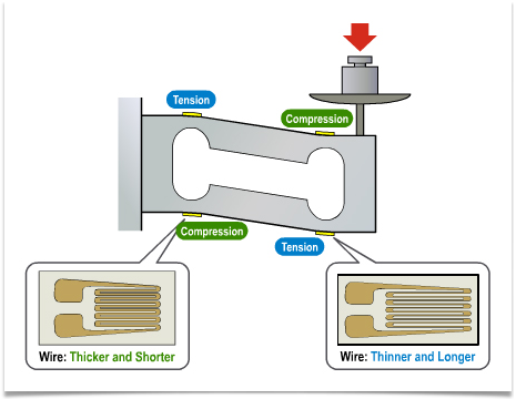
A load cell is a type of transducer that converts physical force into measurable, quantifiable electric energy. Strain Gauge is a device which measures strain, and then transfers that force into electric energy which manifests as measurement. Measuring strain effects helps preserve the integrity of the unit under pressure as well as protects equipment and people nearby.
Strain Gauges in Load Cell
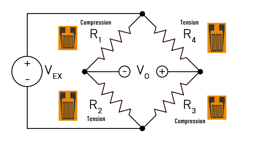
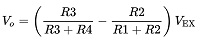
Wheatstone Bridge
In a load cell, the resistors are replaced with strain gauges and arranged in alternating tension and compression formation. When force is exerted on the load cell, the structure and resistance of the strain gauges changes and V0 is measured. From the resulting data, V0 can be easily determined using the equation above.
Load Cell and HX711 Module Caliberation and Test:
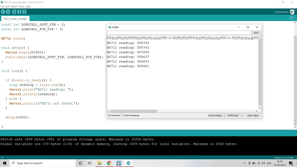
Ran Basic Example Code from the Library
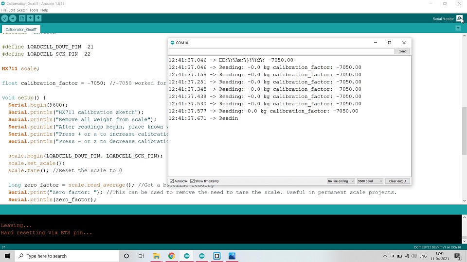
Nathan Siedle's Load Cell Caliberation Code
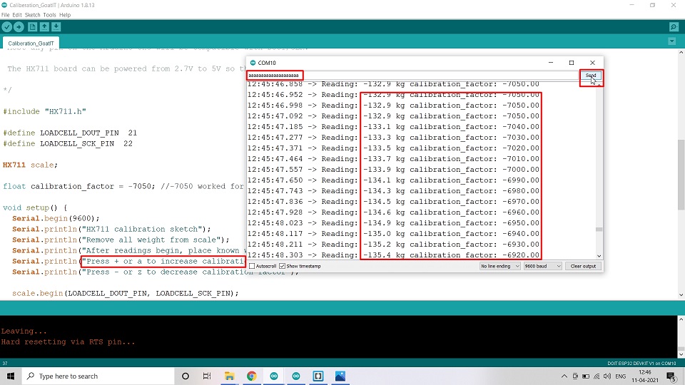
Used a to increase and z to decrease the Caliberation factor
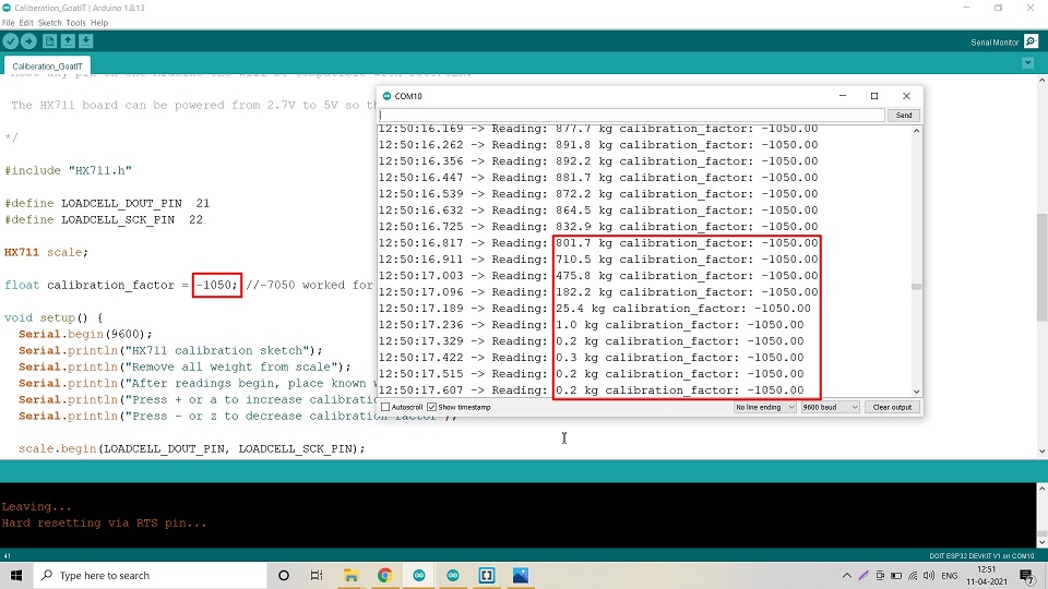
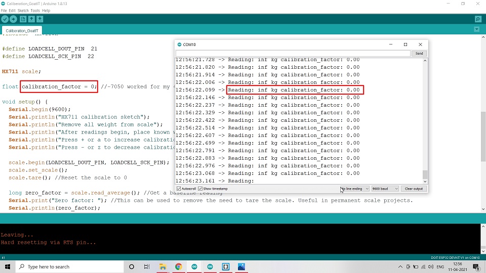
Tried 0 as Caliberation factor
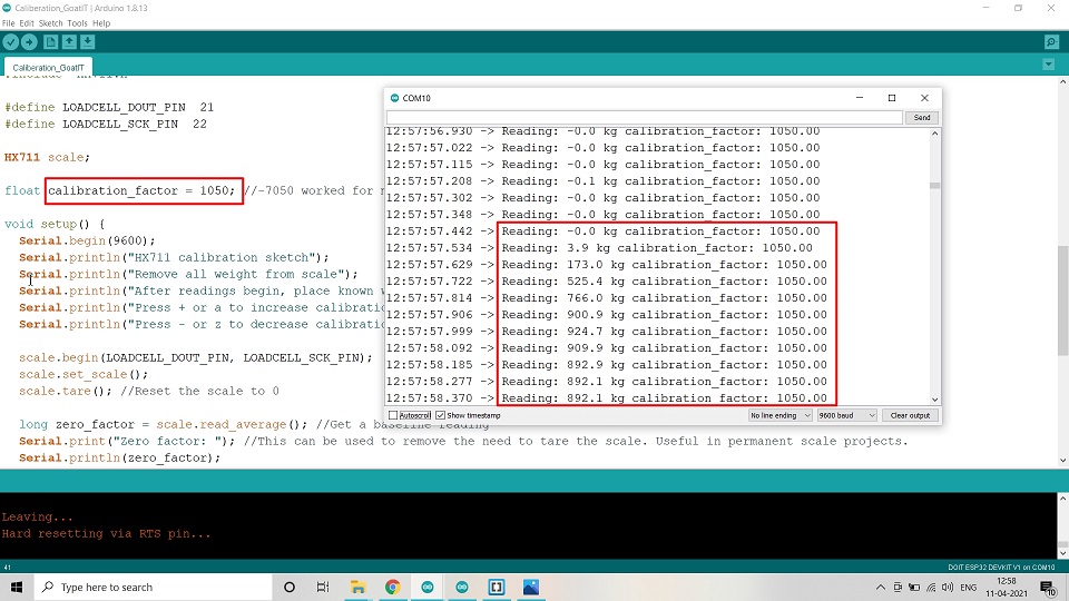
Changed it to +1050 from -1050; then it showed readings near to the Standard weight but in KG and not GM
Test Code:
I have taken the Test Code from Nathan Siedle. I changed the Pin nos. and the Caliberatiopn factor which worked for me was 1400. I also changed the units from Pounds (lbs) to Kg and then to grams as the Load Cell I used was of only 1 Kg.
The code used in Arduino IDE is as given below.
                #include "HX711.h"


                    #define LOADCELL_DOUT_PIN  14

                    #define LOADCELL_SCK_PIN  12


                    HX711 scale;


                    float calibration_factor = 1400; //-7050 worked for my 440lb max scale setup

                    void setup()
 {

                    Serial.begin(9600);

                    Serial.println("HX711 calibration sketch");

                    Serial.println("Remove all weight from scale");

                    Serial.println("After readings begin, place known weight on scale");

                    Serial.println("Press + or a to increase calibration factor");

                    Serial.println("Press - or z to decrease calibration factor");


                    scale.begin(LOADCELL_DOUT_PIN, LOADCELL_SCK_PIN);

                    scale.set_scale();

                    scale.tare(); //Reset the scale to 0


                    long zero_factor = scale.read_average(); //Get a baseline reading

                    Serial.print("Zero factor: "); //This can be used to remove the need to tare the scale. Useful in permanent scale projects.

                    Serial.println(zero_factor);

                    }


                    void loop()
{


                    scale.set_scale(calibration_factor); //Adjust to this calibration factor

                    Serial.print("Reading: ");

                    Serial.print(scale.get_units(), 1);

                    Serial.print(" gm"); //Change this to kg and re-adjust the calibration factor if you follow SI units like a sane person

                    Serial.print(" calibration_factor: ");

                    Serial.print(calibration_factor);

                    Serial.println();


                    if(Serial.available())

                    {

                    char temp = Serial.read();

                    if(temp == '+' || temp == 'a')

                    calibration_factor += 10;

                    else if(temp == '-' || temp == 'z')

                    calibration_factor -= 10;

                    }

                    }
#define LOADCELL_DOUT_PIN 14
#define LOADCELL_SCK_PIN 12
HX711 scale;
float calibration_factor = 1400; //-7050 worked for my 440lb max scale setup
void setup()
{
Serial.begin(9600);
Serial.println("HX711 calibration sketch");
Serial.println("Remove all weight from scale");
Serial.println("After readings begin, place known weight on scale");
Serial.println("Press + or a to increase calibration factor");
Serial.println("Press - or z to decrease calibration factor");
scale.begin(LOADCELL_DOUT_PIN, LOADCELL_SCK_PIN);
scale.set_scale();
scale.tare(); //Reset the scale to 0
long zero_factor = scale.read_average(); //Get a baseline reading
Serial.print("Zero factor: "); //This can be used to remove the need to tare the scale. Useful in permanent scale projects.
Serial.println(zero_factor);
}
void loop()
{
scale.set_scale(calibration_factor); //Adjust to this calibration factor
Serial.print("Reading: ");
Serial.print(scale.get_units(), 1);
Serial.print(" gm"); //Change this to kg and re-adjust the calibration factor if you follow SI units like a sane person
Serial.print(" calibration_factor: ");
Serial.print(calibration_factor);
Serial.println();
if(Serial.available())
{
char temp = Serial.read();
if(temp == '+' || temp == 'a')
calibration_factor += 10;
else if(temp == '-' || temp == 'z')
calibration_factor -= 10;
}
}
RFID Sensor:
RFID or Radio Frequency Identification system consists of two main components, a transponder/tag attached to an object to be identified, and a Transceiver also known as interrogator/Reader. Today in most cases barcodes are used for identifying an item in a warehouse or a supermarket using a barcode scanner, this existing system can be upgraded with the RFID technology. Similar to barcode the RFID can also give unique identification number to all products but the added advantage is unlike the barcode system’s line of sight, this system can detect the RFID tag within its proximity range.
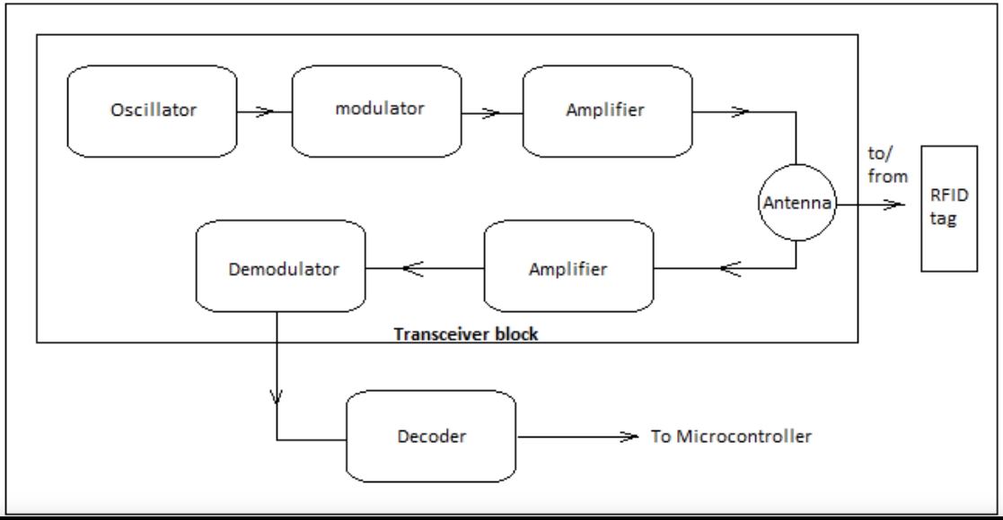
RFID Working System Construction
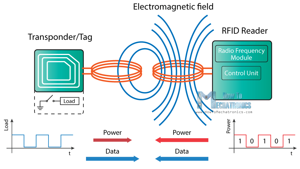
RFID Working System Construction
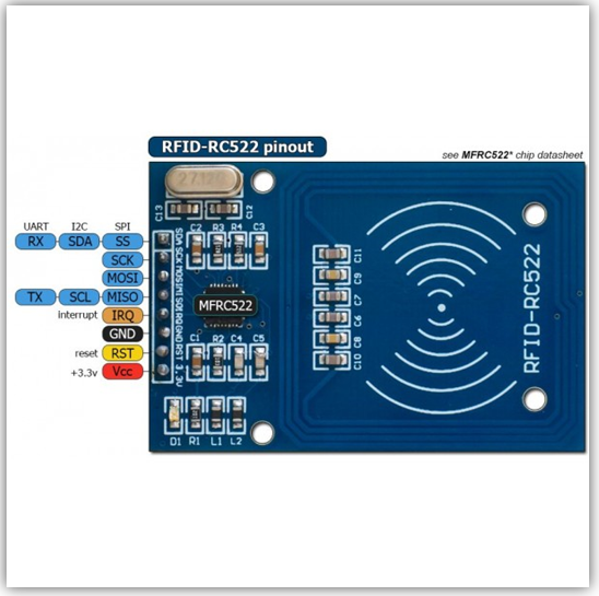
RFID Reader - MFRC522
I used one of the examples of Dump Info to test the RFID reader and the Tag. I changed the Pin nos. and also identified the UID of the Tag.
The code used in Arduino IDE is as given below.
                #include SPI.h

                    #include MFRC522.h


                    #define RST_PIN         22          // Configurable, see typical pin layout above

                    #define SS_PIN          21         // Configurable, see typical pin layout above


                    MFRC522 mfrc522(SS_PIN, RST_PIN);  // Create MFRC522 instance


                    void setup()
{

                    Serial.begin(9600);		// Initialize serial communications with the PC

                    while (!Serial);		// Do nothing if no serial port is opened (added for Arduinos based on ATMEGA32U4)

                    SPI.begin();			// Init SPI bus

                    mfrc522.PCD_Init();		// Init MFRC522

                    delay(4);				// Optional delay. Some board do need more time after init to be ready, see Readme

                    mfrc522.PCD_DumpVersionToSerial();	// Show details of PCD - MFRC522 Card Reader details

                    Serial.println(F("Scan PICC to see UID, SAK, type, and data blocks..."));

                    }


                    void loop()
{

                    // Reset the loop if no new card present on the sensor/reader. This saves the entire process when idle.

                    if ( ! mfrc522.PICC_IsNewCardPresent()) {

                    return;

                    }


                    // Select one of the cards

                    if ( ! mfrc522.PICC_ReadCardSerial()) {

                    return;

                    }


                    // Dump debug info about the card; PICC_HaltA() is automatically called
                    mfrc522.PICC_DumpToSerial(&(mfrc522.uid));

                    }
#include MFRC522.h
#define RST_PIN 22 // Configurable, see typical pin layout above
#define SS_PIN 21 // Configurable, see typical pin layout above
MFRC522 mfrc522(SS_PIN, RST_PIN); // Create MFRC522 instance
void setup()
{
Serial.begin(9600); // Initialize serial communications with the PC
while (!Serial); // Do nothing if no serial port is opened (added for Arduinos based on ATMEGA32U4)
SPI.begin(); // Init SPI bus
mfrc522.PCD_Init(); // Init MFRC522
delay(4); // Optional delay. Some board do need more time after init to be ready, see Readme
mfrc522.PCD_DumpVersionToSerial(); // Show details of PCD - MFRC522 Card Reader details
Serial.println(F("Scan PICC to see UID, SAK, type, and data blocks..."));
}
void loop()
{
// Reset the loop if no new card present on the sensor/reader. This saves the entire process when idle.
if ( ! mfrc522.PICC_IsNewCardPresent()) {
return;
}
// Select one of the cards
if ( ! mfrc522.PICC_ReadCardSerial()) {
return;
}
// Dump debug info about the card; PICC_HaltA() is automatically called mfrc522.PICC_DumpToSerial(&(mfrc522.uid));
}
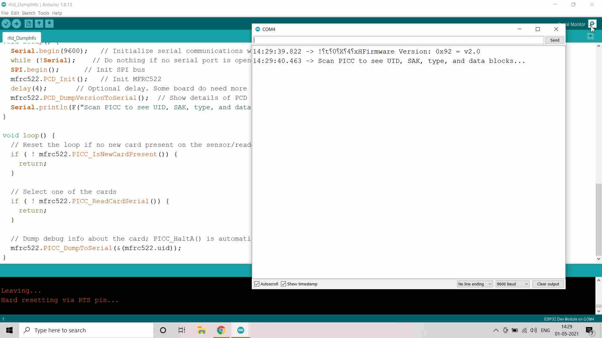
Tested Rfid Dump Info Code
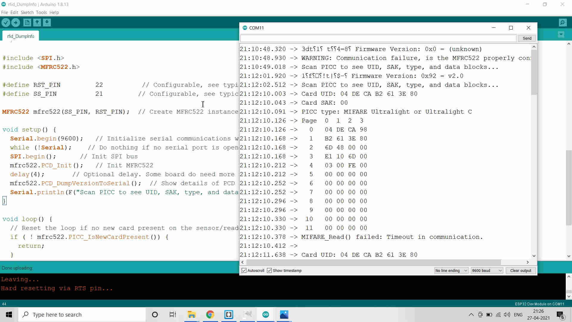
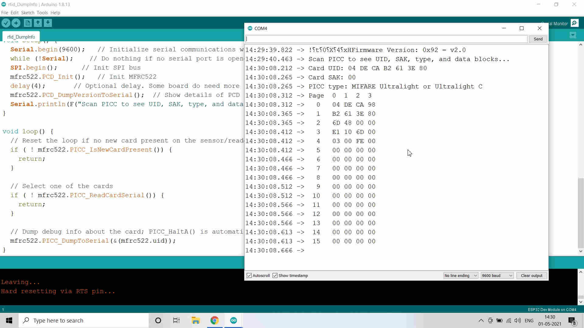
Successfully Scanned the RFID Tag
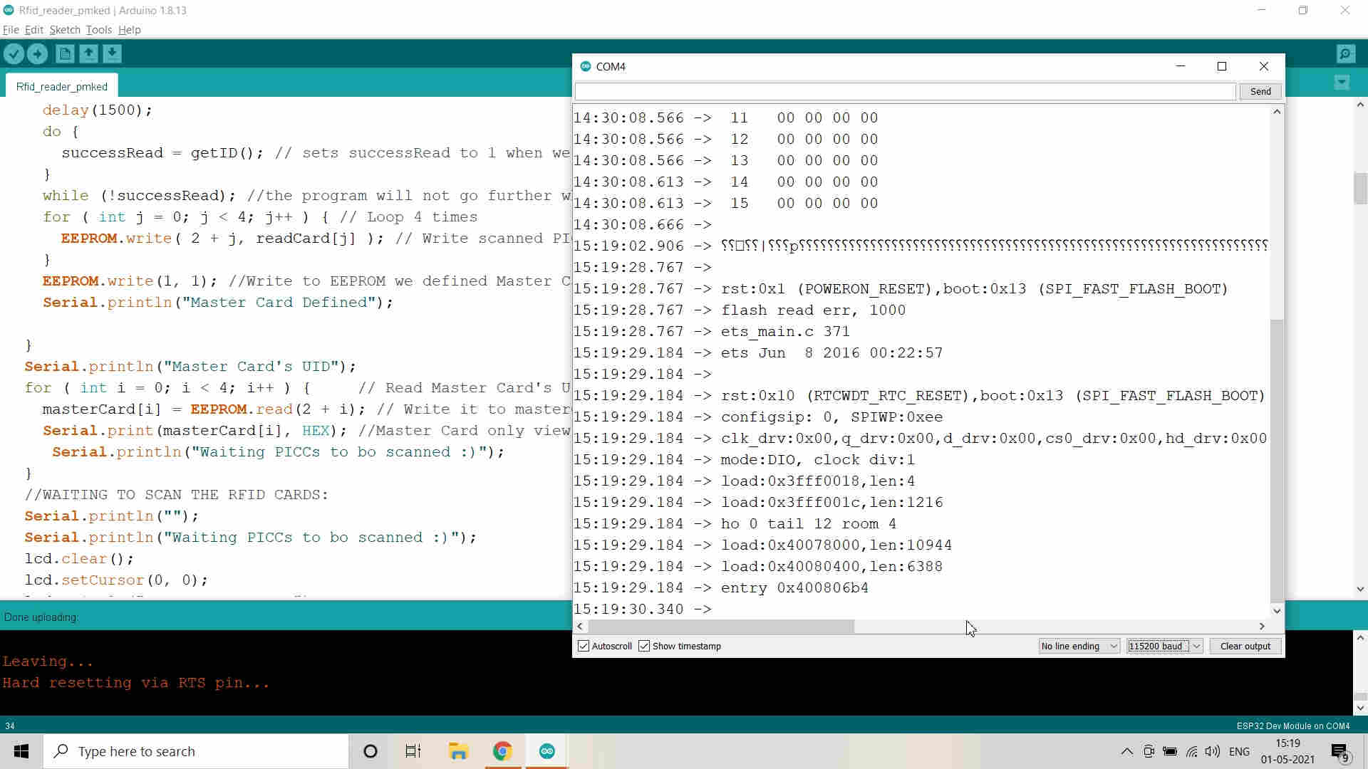
Edited the Code to integrate with LCD
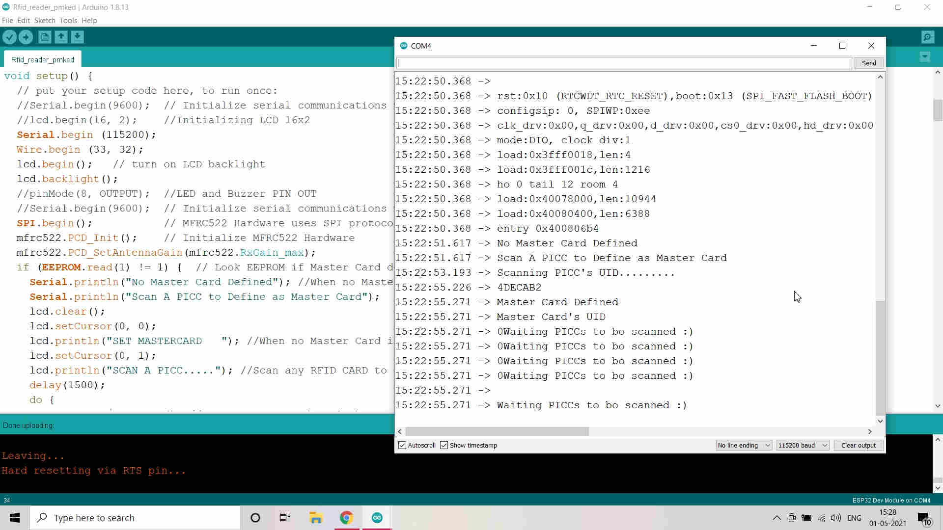 Successfully compiled the Code and Verified
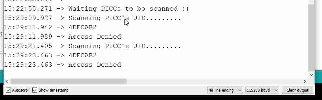 Scanned the Tag which is not Master Tag and thats why Access denied
ESP 32 MicroController:
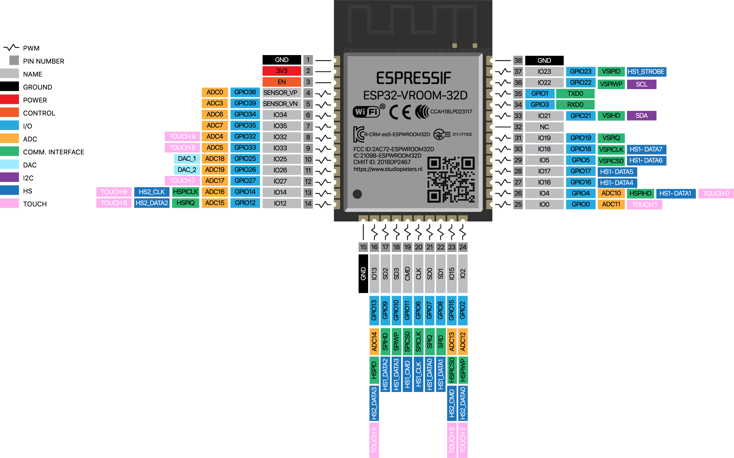
ESP 32 Microcontroller and Pin Out
PCB Design in Eagle:
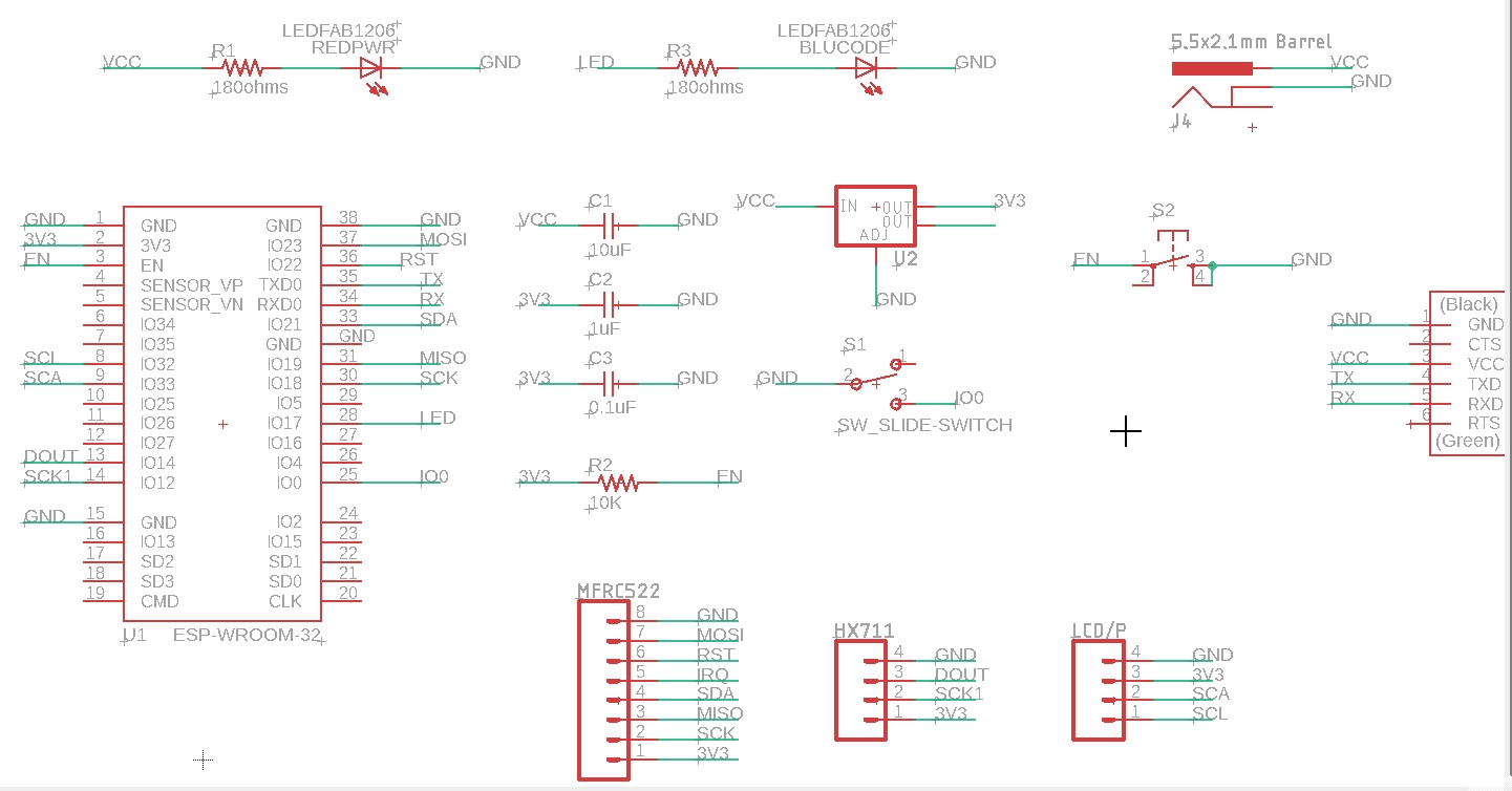
Schematic and Components used for PCB Designing in Eagle
I struggled a lot for 2 days to solve the vias and route the connections of esp32 and mfrc522 module. The pins are all mixed and I found it really difficult to clear the vias.
My friend suggested me to use the zero ohm resistors as jumpers to cross the connections. I used them as well.
But then I changed the Pin names of the connector pins to make it simple. This is how the pins were connected easily and in straight line.
I will have to remember to connect the pins correctly to the connector in order.
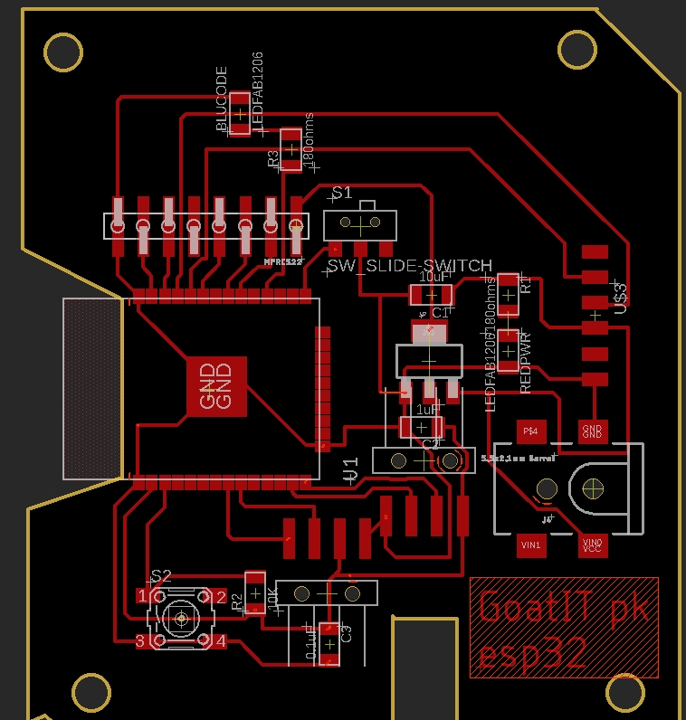
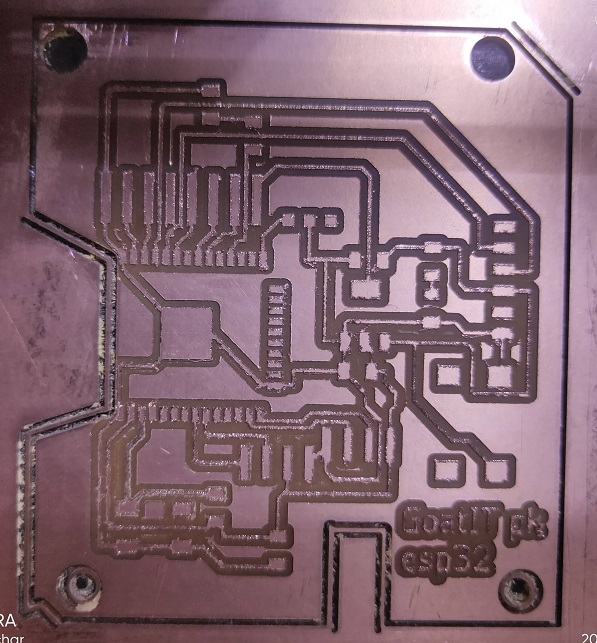
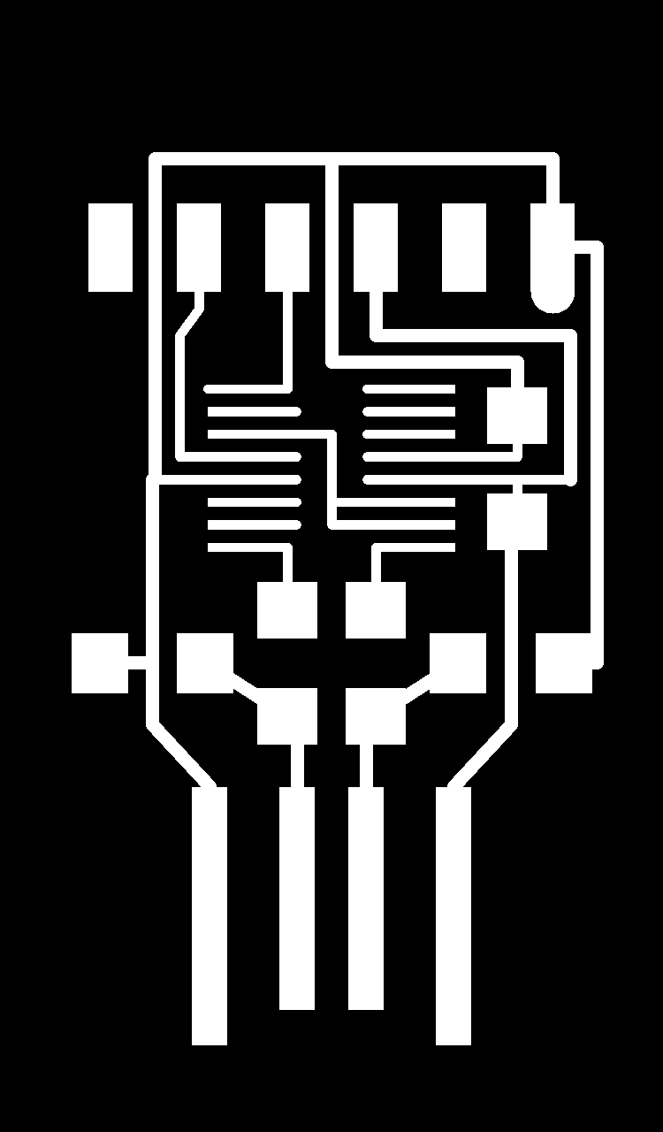
PCB Board Design in Eagle
| PCB Traces | PCB Outer Cut |
|---|---|
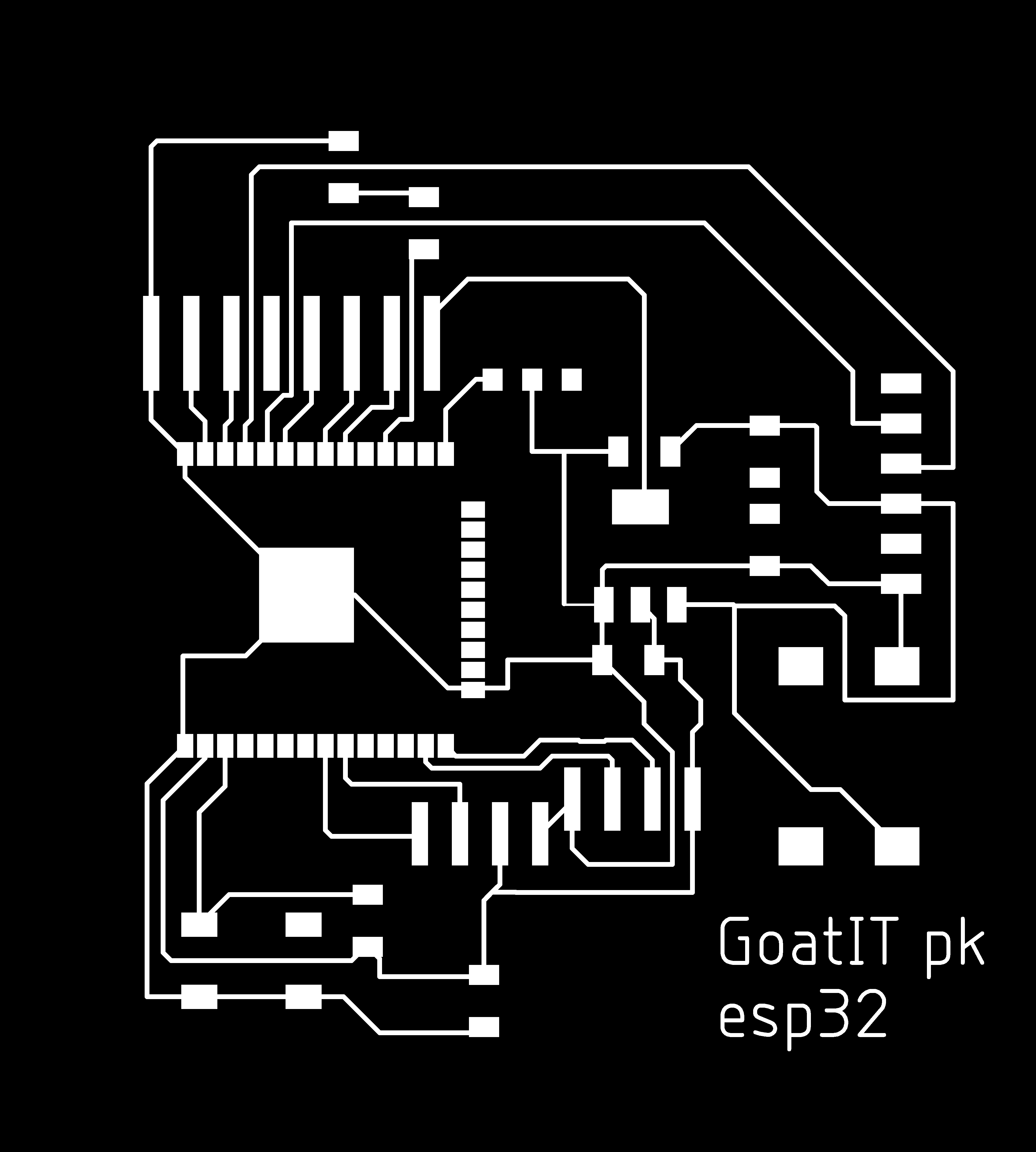 | 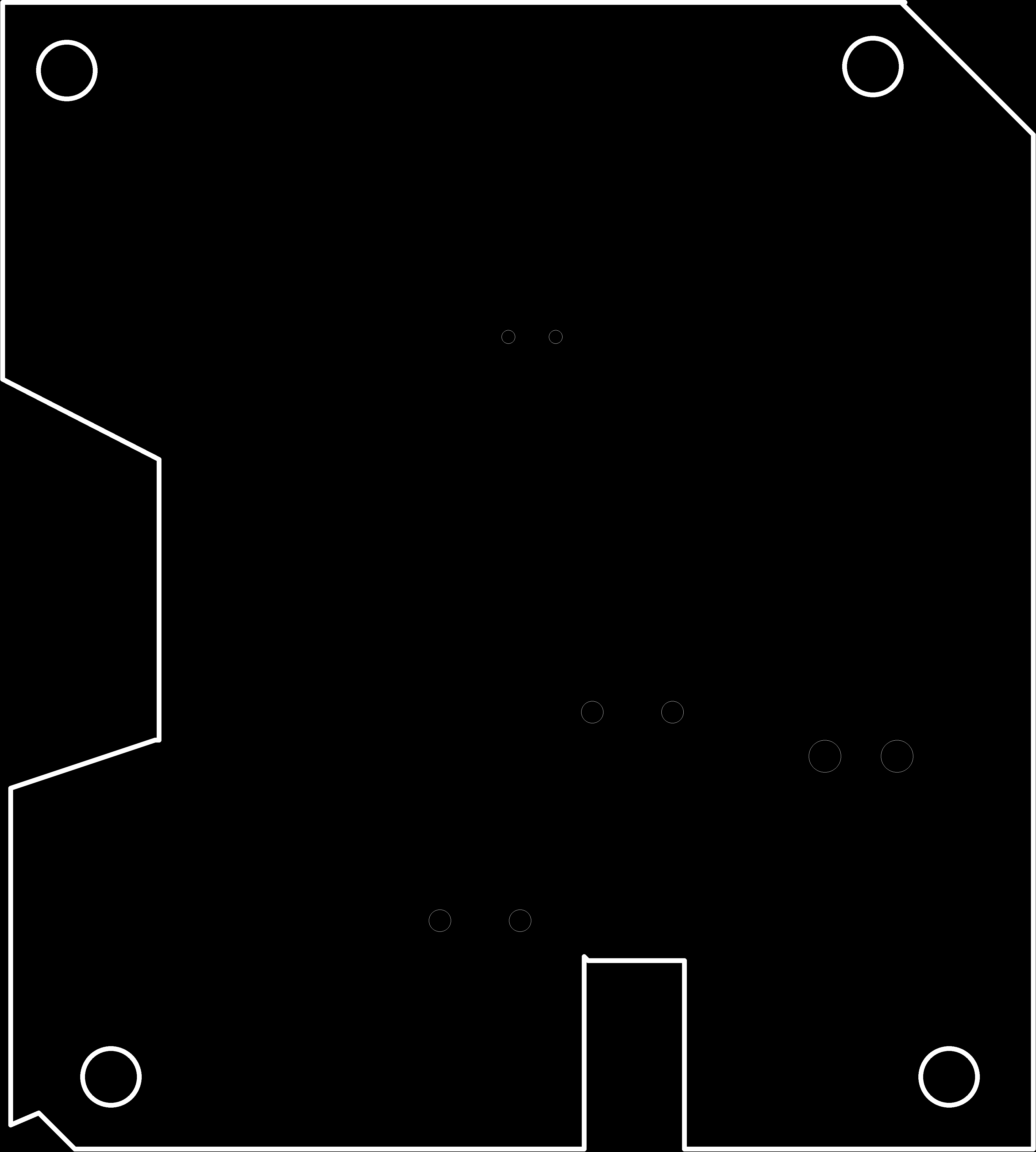 |
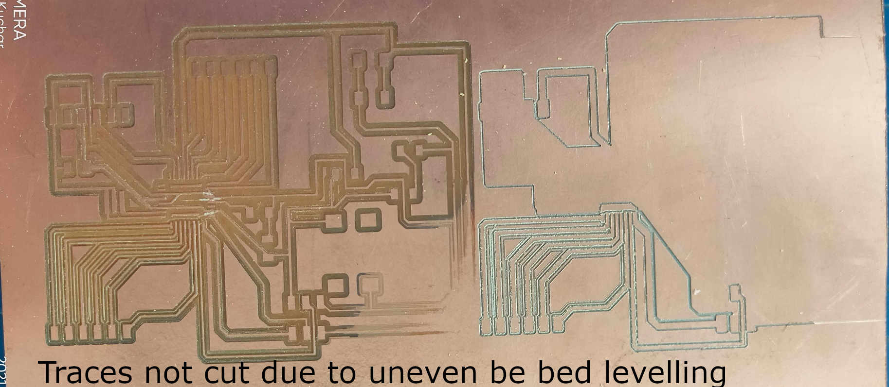
PCB Milling
Due to some technical fault in the SRM-20 and bed levelling issue, we were not able to mill our PCB boards and hence couldnt solder the components and make our PCB.
For the bed levelling issue, we have removed the sacrificial layer and applied the acrylic sheet. Still, we had the levelling issue. Then we milled the acrylic sheet applied as sacrificial layer using the 1/8 mill bit for making it even and levelling.
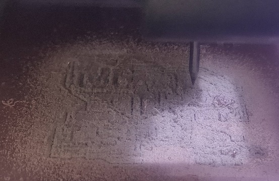
Issue while Milling the PCB plates
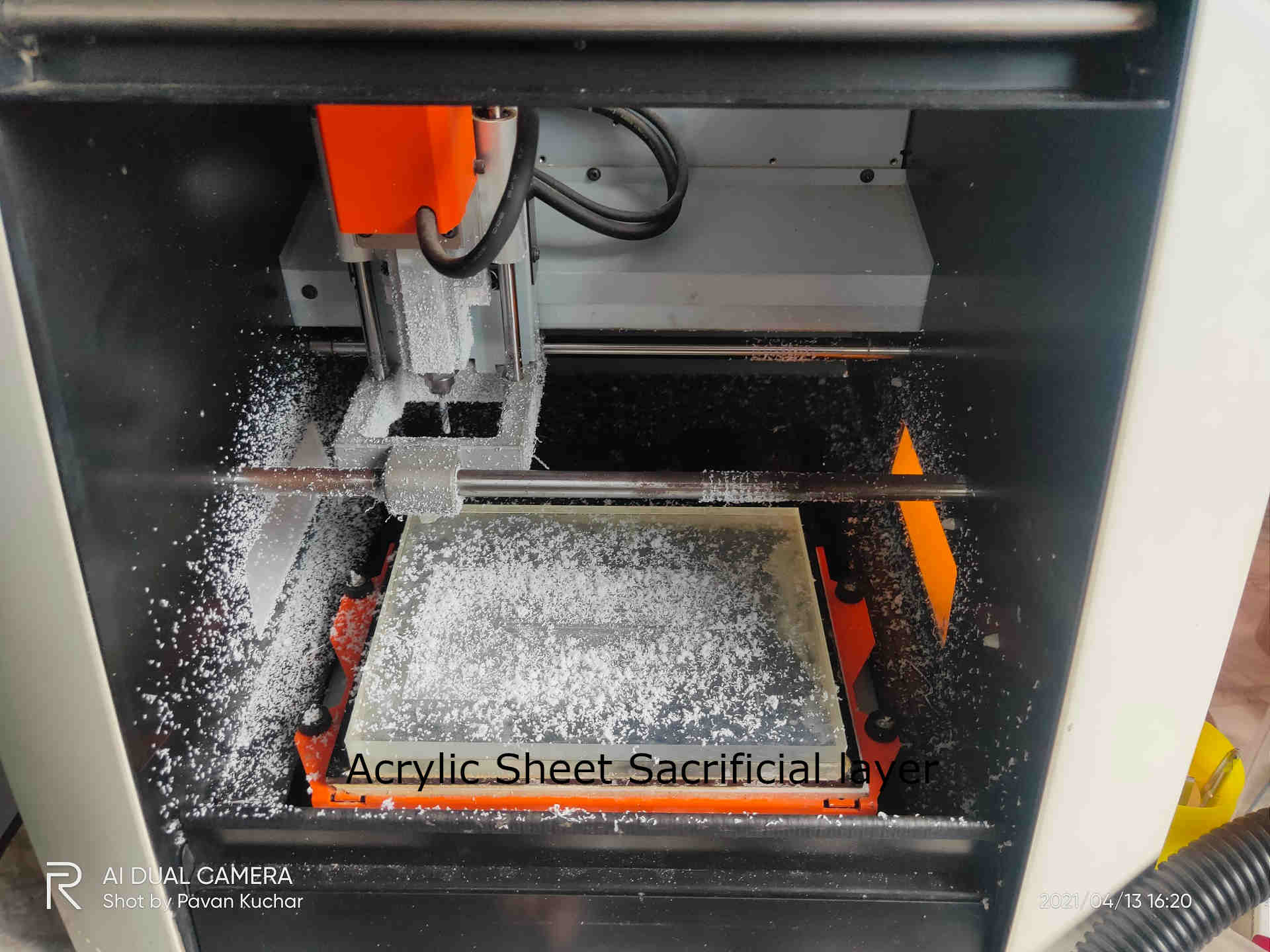
Acrylic Sheet Sacrificial layer levelling using 1/8 mill bit
In the Output Devices's Week Assignment, I milled the ESP-32 PCBoard that I have already prepared as the SRM-20 machine was not not free and under use for the Molding and Casting week.
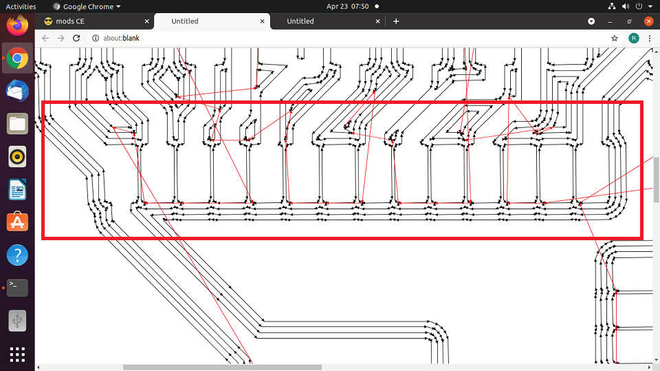
I uploaded the PCB Schematic Board on the Mods for milling the traces but the Traces in between the pads of ESP-32 Microcontroller pins were not visible after calculating the Mill raster 2D.
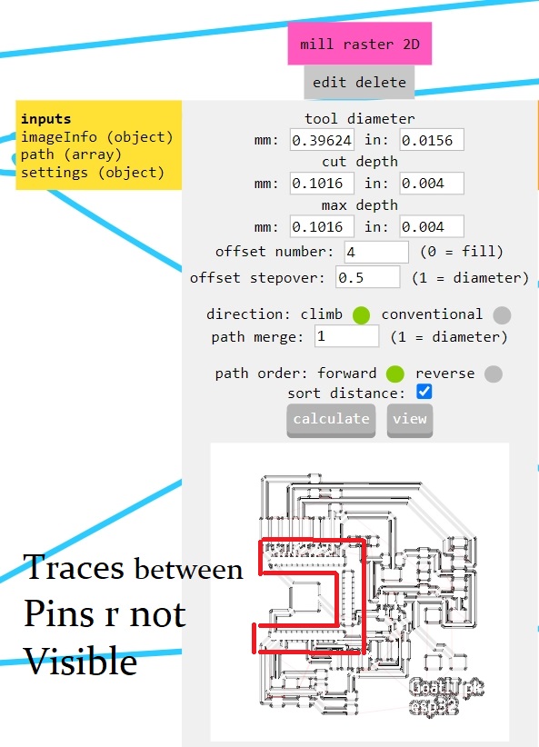
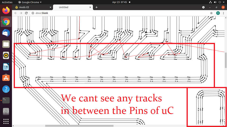
Traces in Pins of uC not Visible means the machine will not Mill them
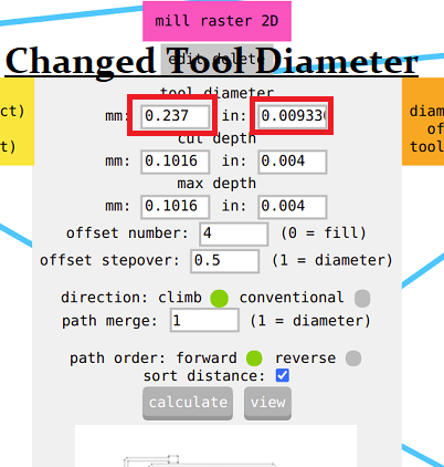
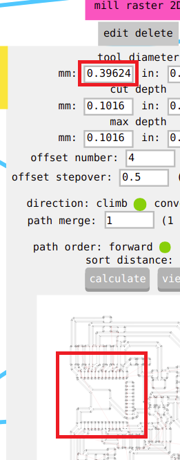
I tried to change the Tool Diameter
At almost half the Standard Tool Diameter, The Traces were visible
But, I was not allowed to change the Tool Diameter and asked to think about alternative way. I tried to check the Net Labels and changed the Pad size. Also, changed in the DRC but Alas! nothing worked.
Later out FabLab Manager, Mr. Suhas came to my rescue and suggested me to go through the webpage of Chaitanya Gosavi Fab Academian of Vigyan Ashram 2018.
He had reduced the size of the pads by making changes in the footprints. The command used was "change smd". I tried to follow his steps and I succeded in reducing the pad size. The Troubleshooting steps are as given.
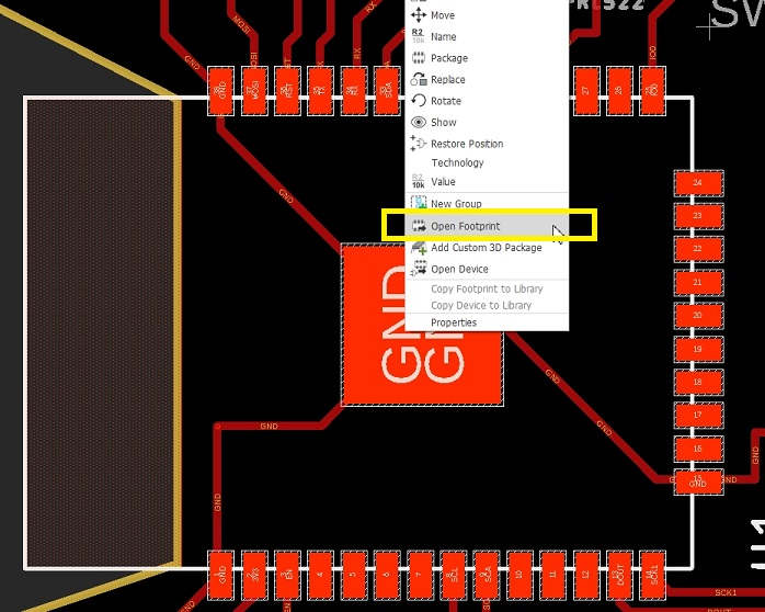
Right Click on the Plus Sign of the Component(ESP-32 uC in my case) and select Open Footprint
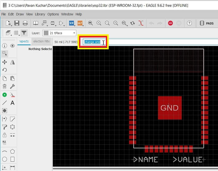
Type "change smd" in the command line
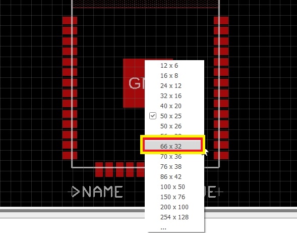
Select the desired size of the pads from the dropdown menu
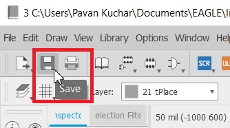
Save the Changes
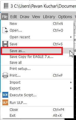
Save as the desired file name in the libraries of ESP-32 of Eagle
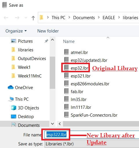
I saved it by the name esp322
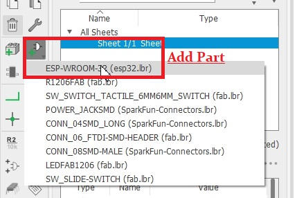
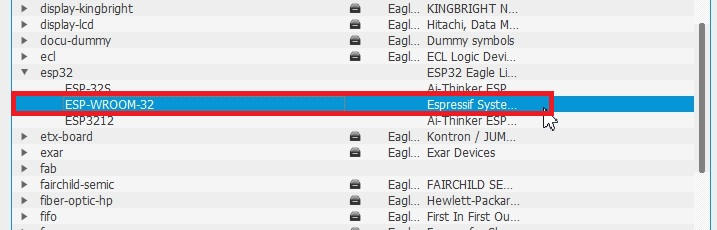
Go to Schematic and Add Part esp32.
The Warning window will pop up saying that
the file already exists and do you want to update. Click Yes/OK.
Your changes will appear in the new esp-32 uC part.
Delete any of the esp-32 uC part in the Schematic. Check the Board and the changes will reflect.
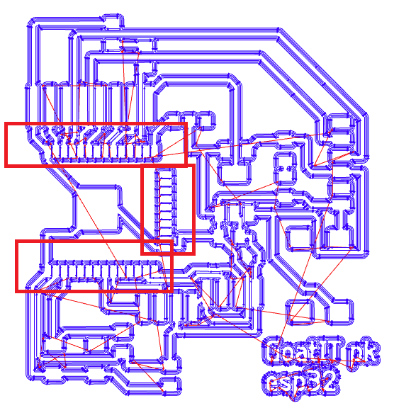
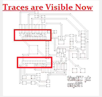
Checked it in the Mods after calculating on the Default settings of Tool Diameter
Now I can see the Traces between the Pins of esp-32 uC
I changed the Cut Depth and Max. Depth because the PCB plate that I was using was not of that much height. If kept the same settings, it might cut the Sacrificial layer of the machine bed.
| Out Cut Settings | Out Cut Changed Settings |
|---|---|
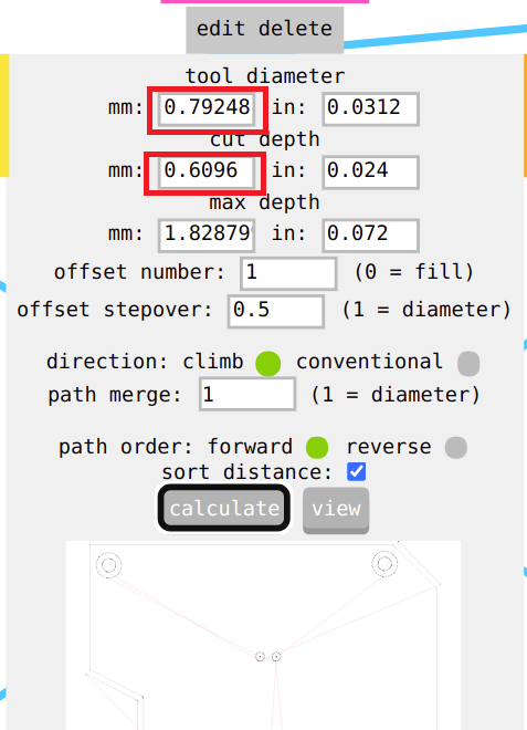 Default Cut Out Settings | 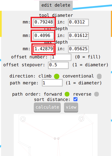 Changed Cut Out Settings |
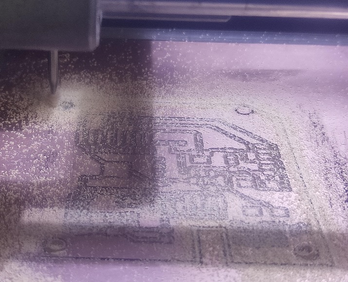
Traces Milling Ongoing
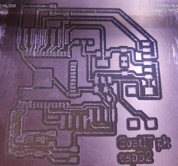
Milled Traces on PCB
 Outer Cut Ongoing | 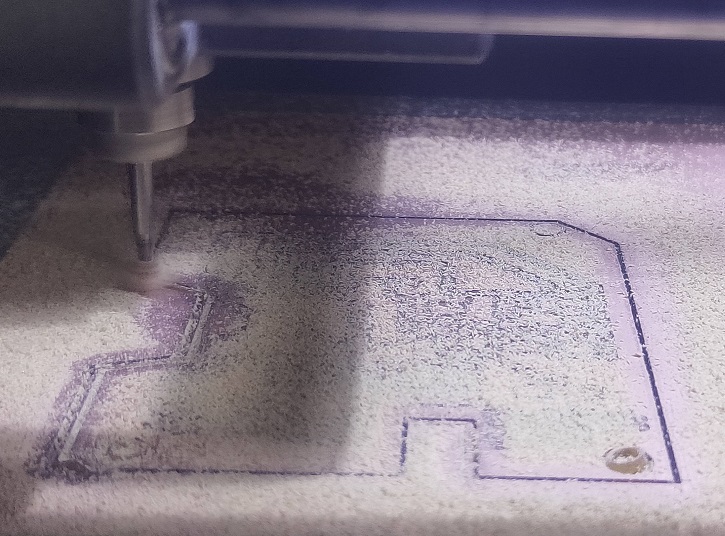 Outer Cut Ongoing |
 Milling Job Done | 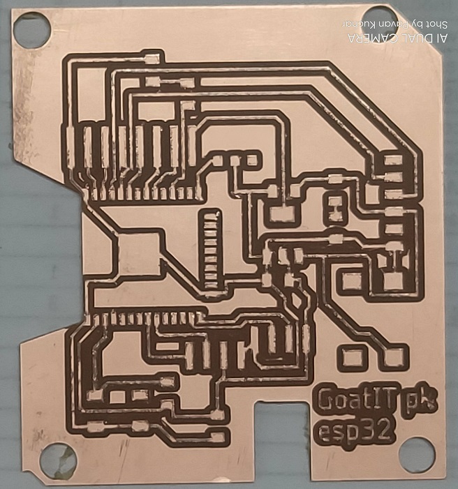 PCBoard after Milling and Cutting |
PCB Stuffing and Soldering:
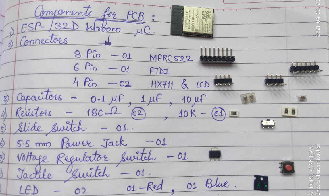
Components required for Soldering on the PCB
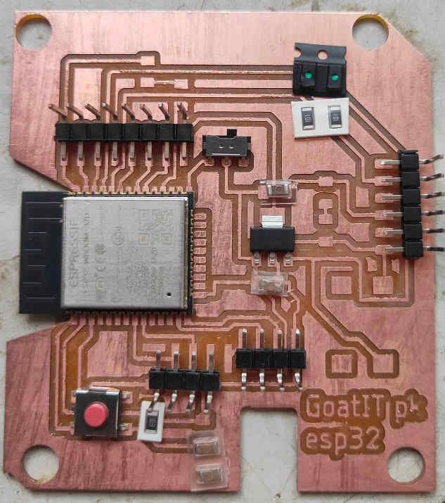 Stuffing the components on the PCB | 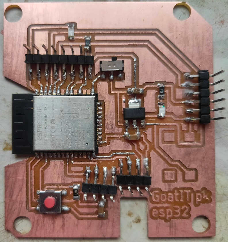 Soldered PCB Ready for the Action |
PCB Programming and Interfacing with the Sensors and Modules:
I downloaded the traces of FTDI from Embedded Programming Week. Milled the Board and Soldered the Components. This is how I prepared the FTDI Cable for connecting with my ESP-32 board. I have shared earlier the Programs and Sketch/Codes that I have used for my Final Project. The codes for MFRC522 (RFID Tag Reader) and HX711 (Load Cell) were used and tested on my board for this week.
Summary:
This is a very important week from my Final Project's perspective and it helped me to design and complete the PCB for my project.
- I was familiarized with various Input Devices that could be used.
- I also came to know about the various principles on which these Input Devices / Sensors work like Resistance, Capacitance, Inductance etc. Load Sensors are also called as Transducer.
- I learned about the Wheatstone Bridge.
- I tried testing / probing the Sensors
- I designed, milled and soldered the components on my PCB.
Downloads: Original Files
The Original .ino Files of my Sketch / Codes could be downloaded from here.