Output Devices
Group assignment:
Individual assignment:
An ACTUATOR is an inherently mechanical device whose function is to provide force to move or "actuate" another mechanical device. The force provoked by the actuator comes from three possible sources: pneumatic pressure, hydraulic pressure, and electrical motive force (electric motor or solenoid).
There are two main types: single-acting cylinders and double-acting cylinders. Rotary actuators: they are in charge of transforming pneumatic energy into rotational mechanical energy. There are two groups: limited-turn actuators and pneumatic motors. Special actuators.
Thinking about the final project and having concluded the allocation of inputs for this week, it was decided to use a humidity sensor which will determine the water needs of the plants that will be at the top of the bus stop.
To carry out this work, a water pump plus the humidity sensor will be used, this water pump will be activated when the humidity sensor indicates it according to previously configured parameters.
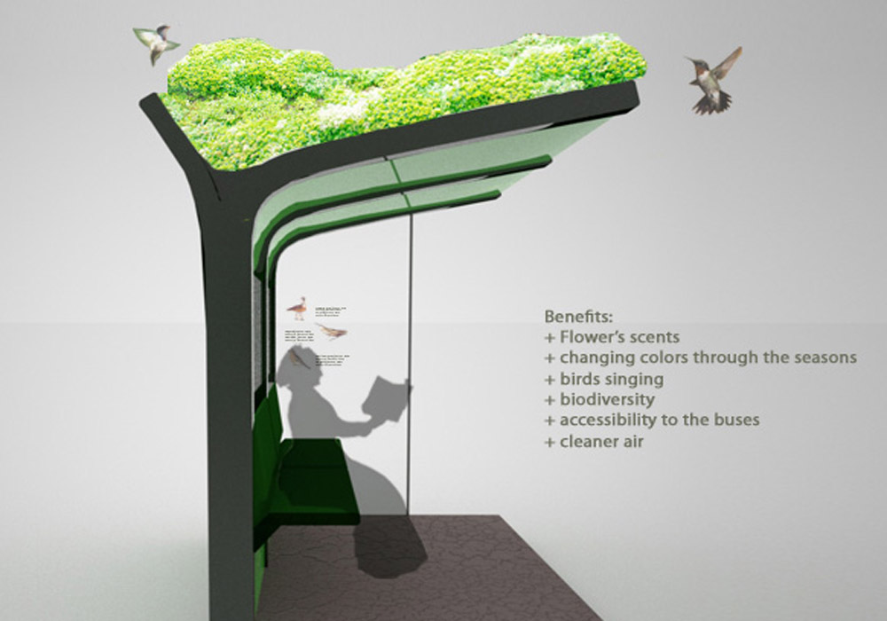 Image taken from conceptodisenio
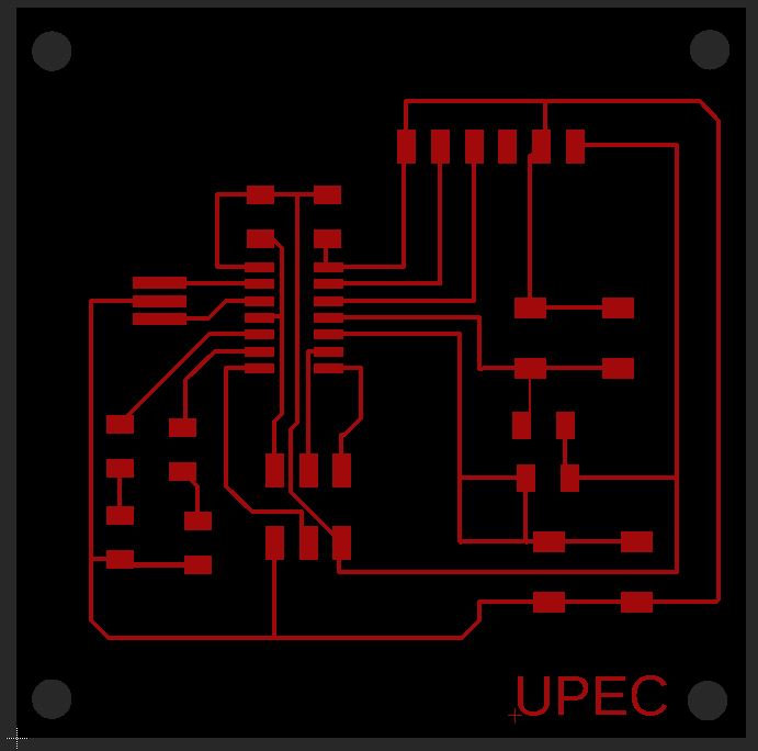
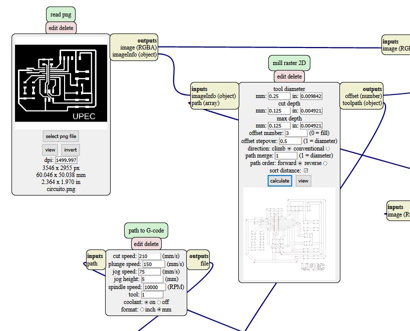
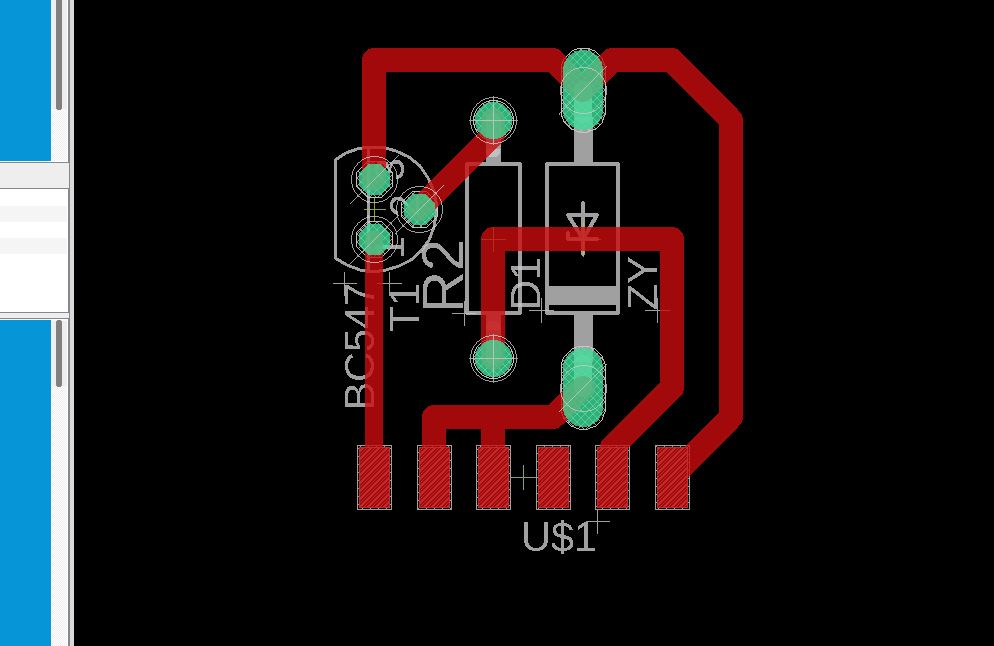
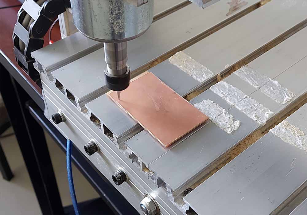
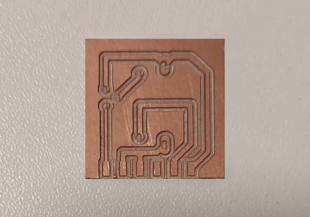
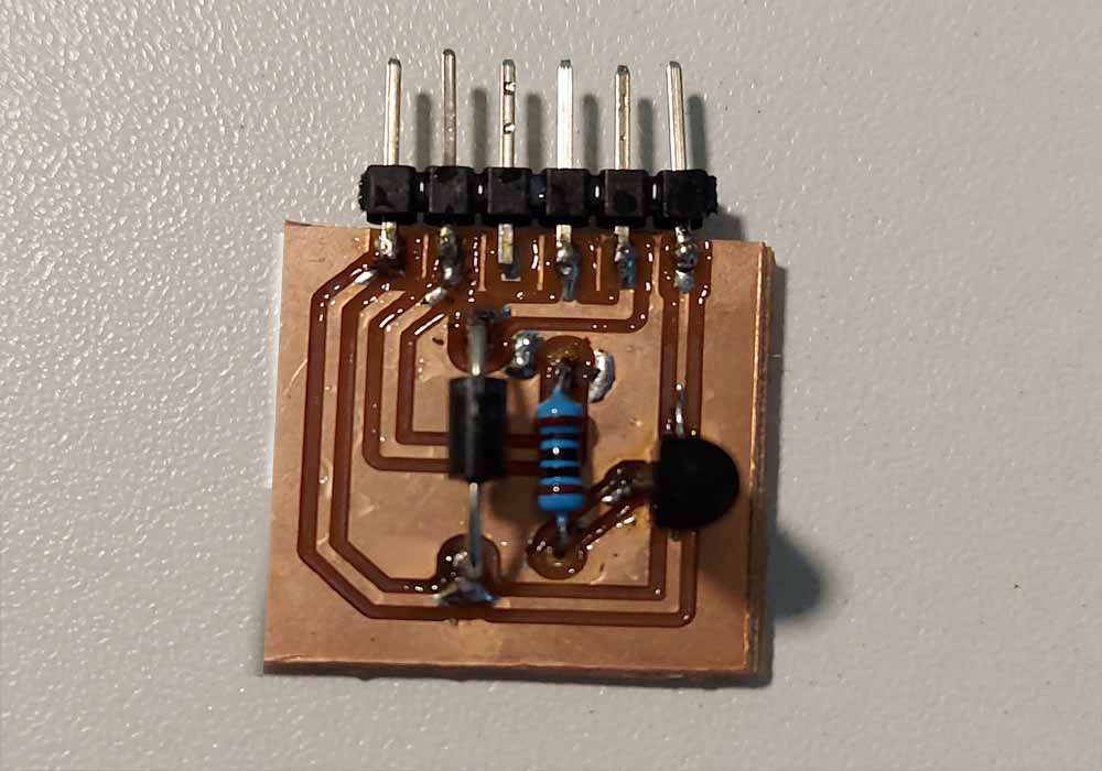
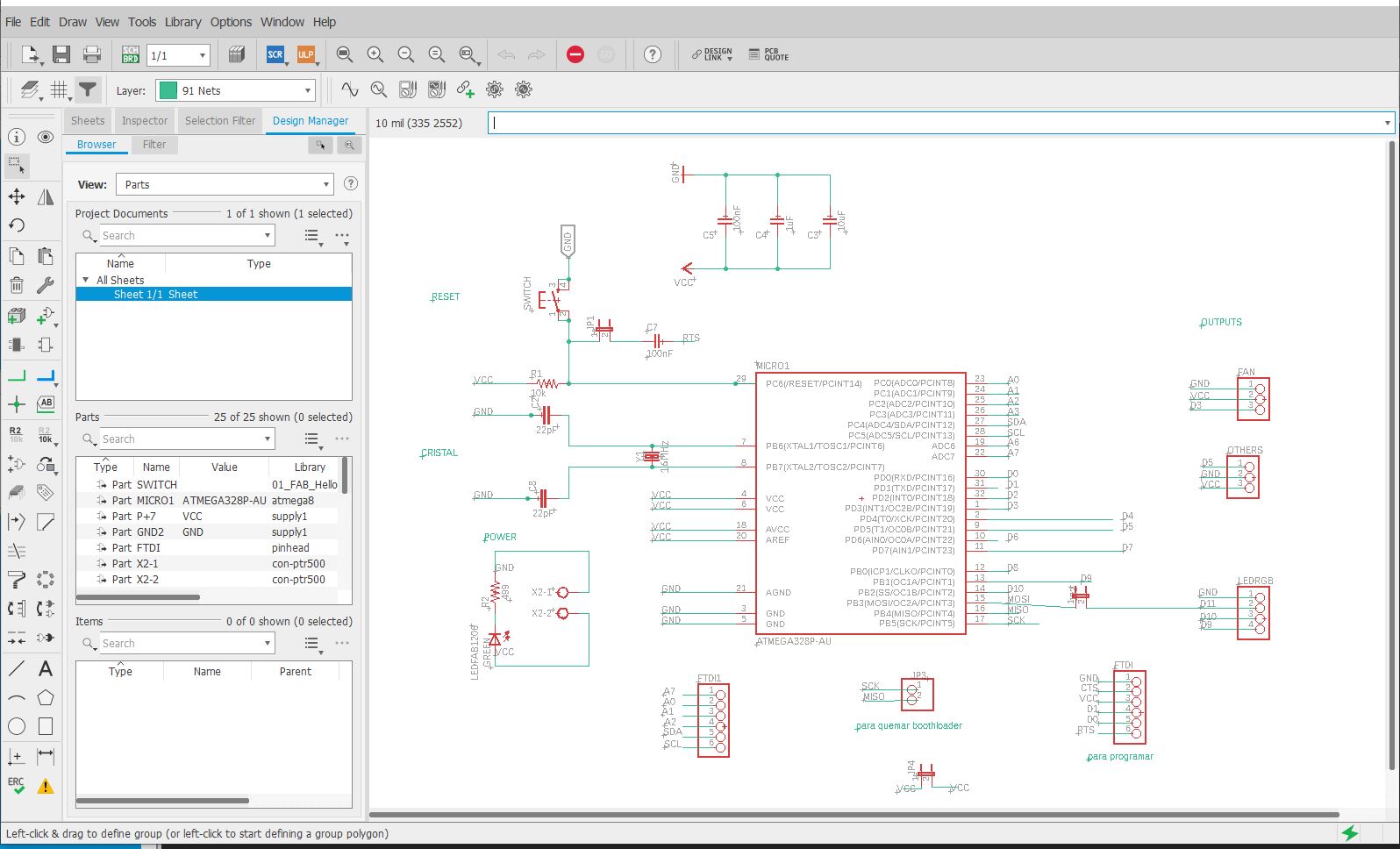
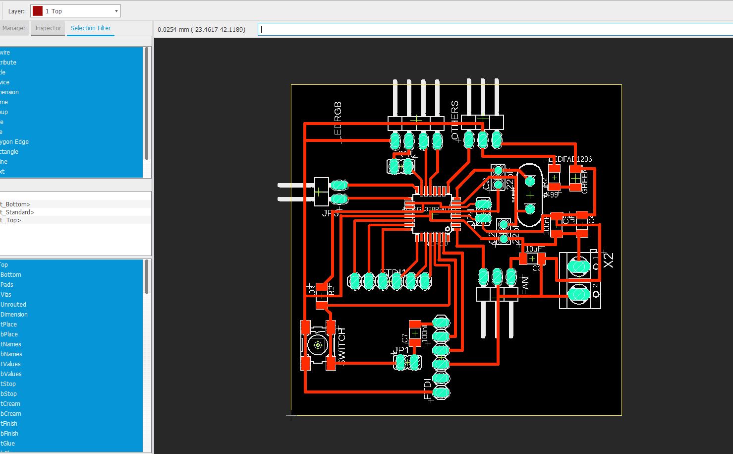
For this we will use the design made in electronic design that is based on the ATtiny 44 controller, this week we already tried to connect some sensors to our circuit board in conjunction with several LEDs that indicated that the expected parameters were received
you can download the necessary files from the following links
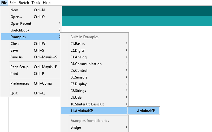
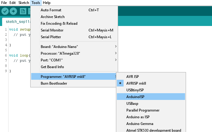
For this assignment we will use the same design used in embedded programming since this design has free pins to connect our sensor, You can watch the entire creation process and download the files at the following link, embedded programming


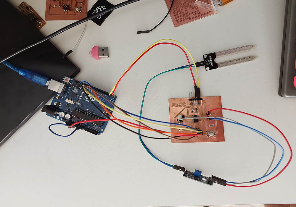
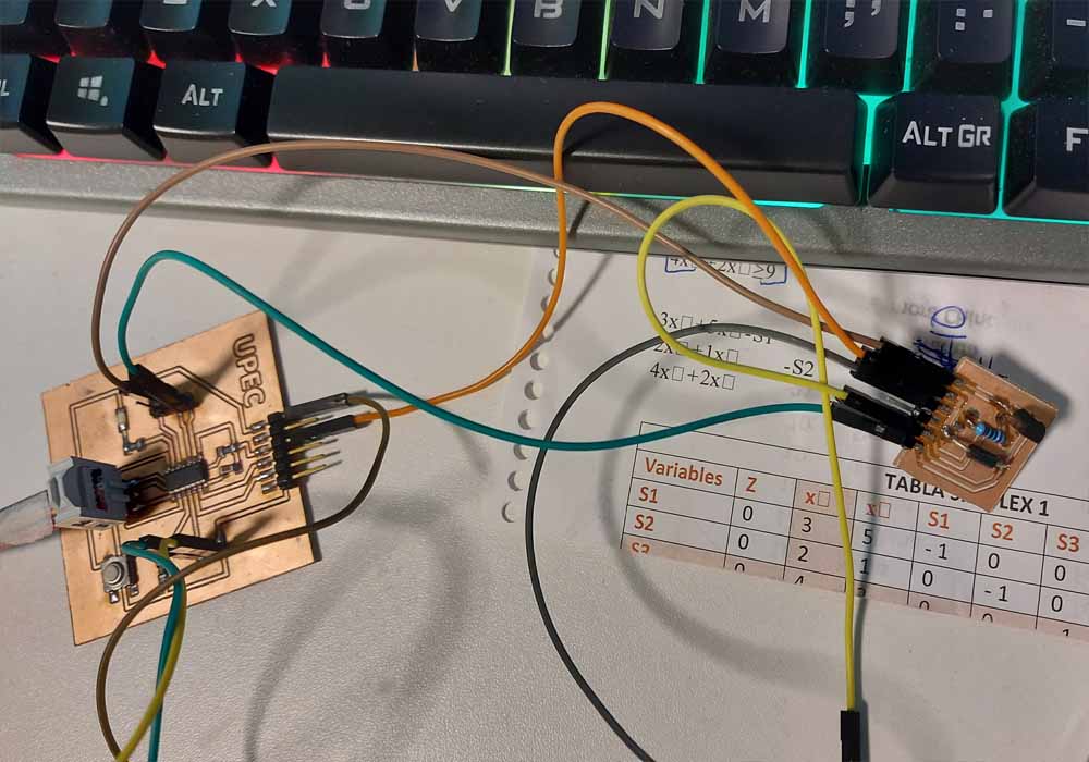
In this first attempt we are going to connect the humidity sensor, carry out the verification of the pins and the necessary programming to be able to receive data from the sensor, then we will integrate the led included in the printed circuit board.
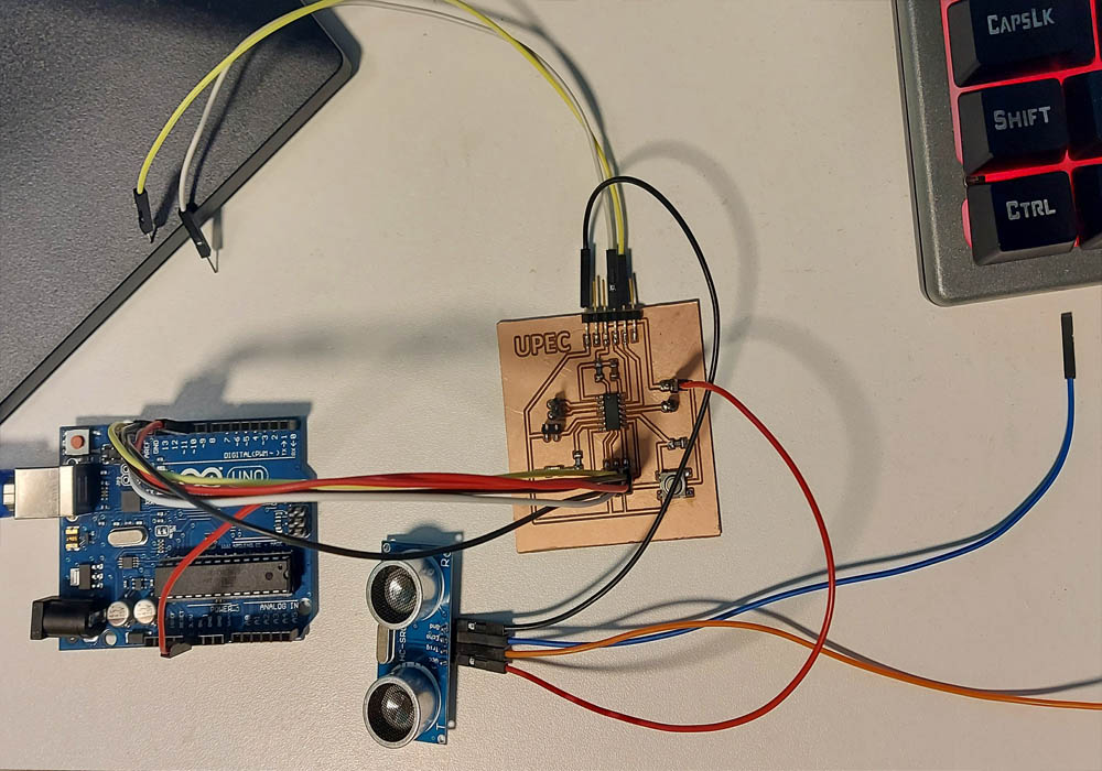
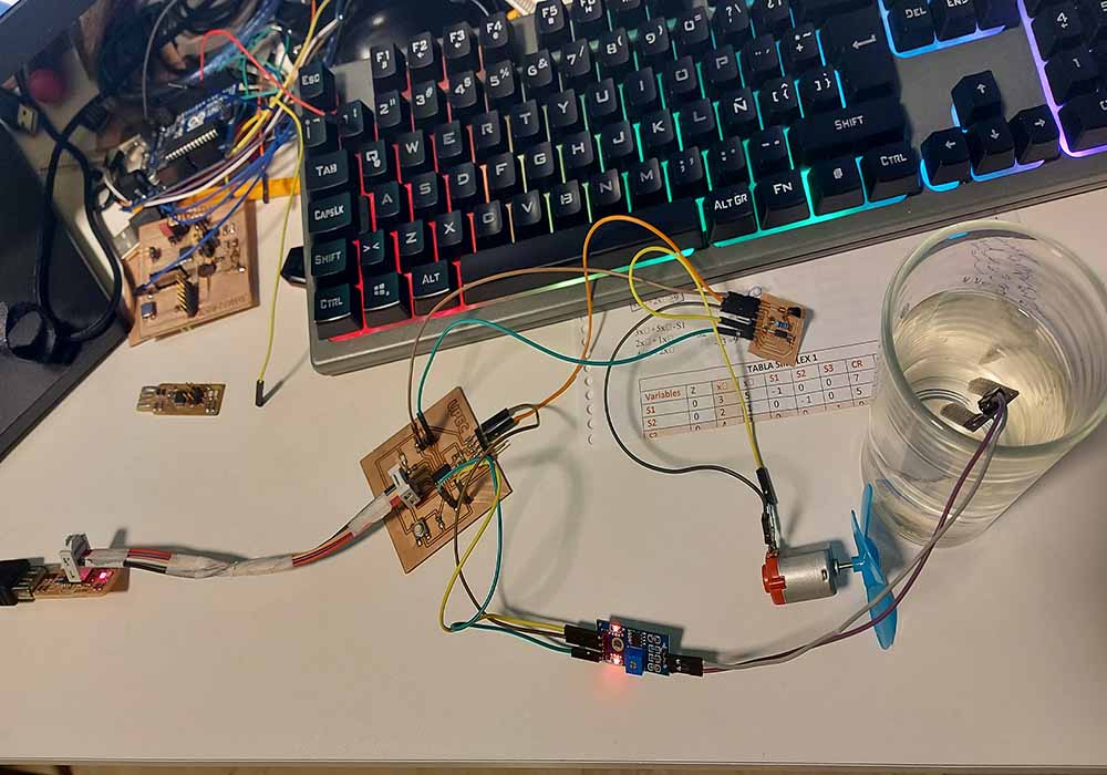
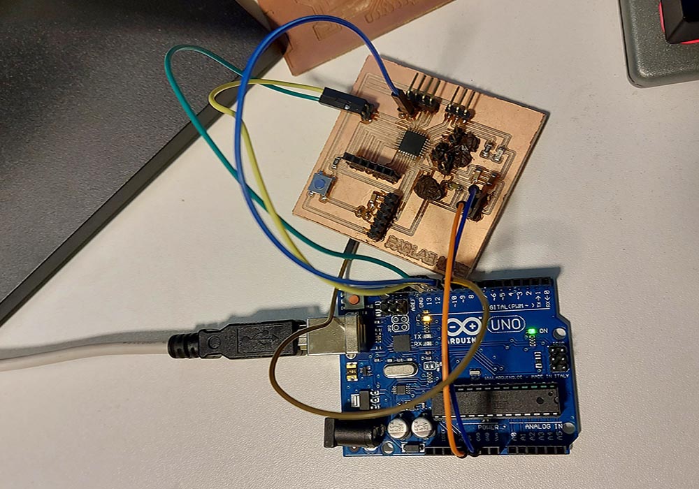
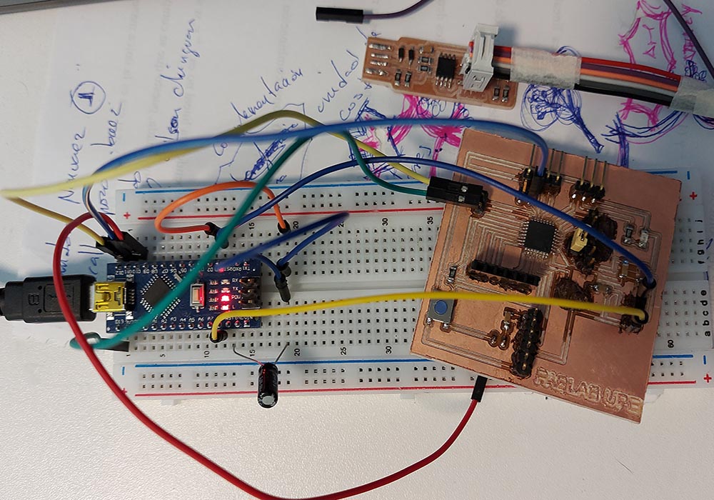
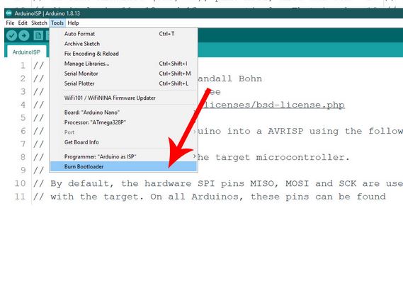
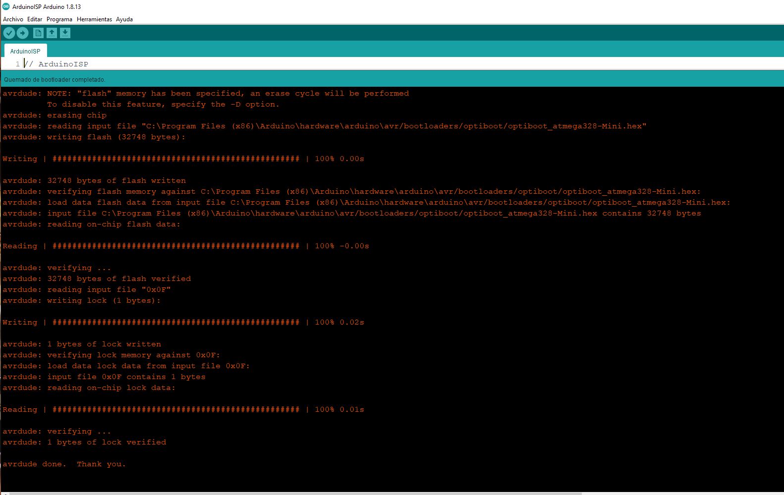
We will connect a proximity sensor to our circuit, For this we will first use our Arduino as a programmer, and we will load the code to control the proximity sensor, In addition, we will control the parameters indicated in the code with the on and off of a led integrated in the circuit board
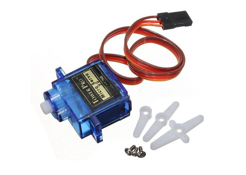
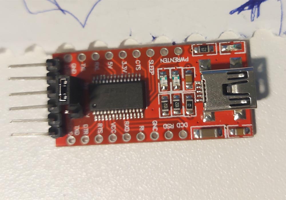
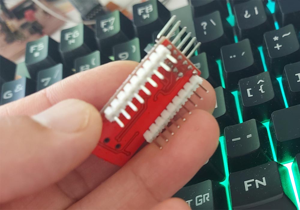
You will need the following components to add the motor to the circuit board
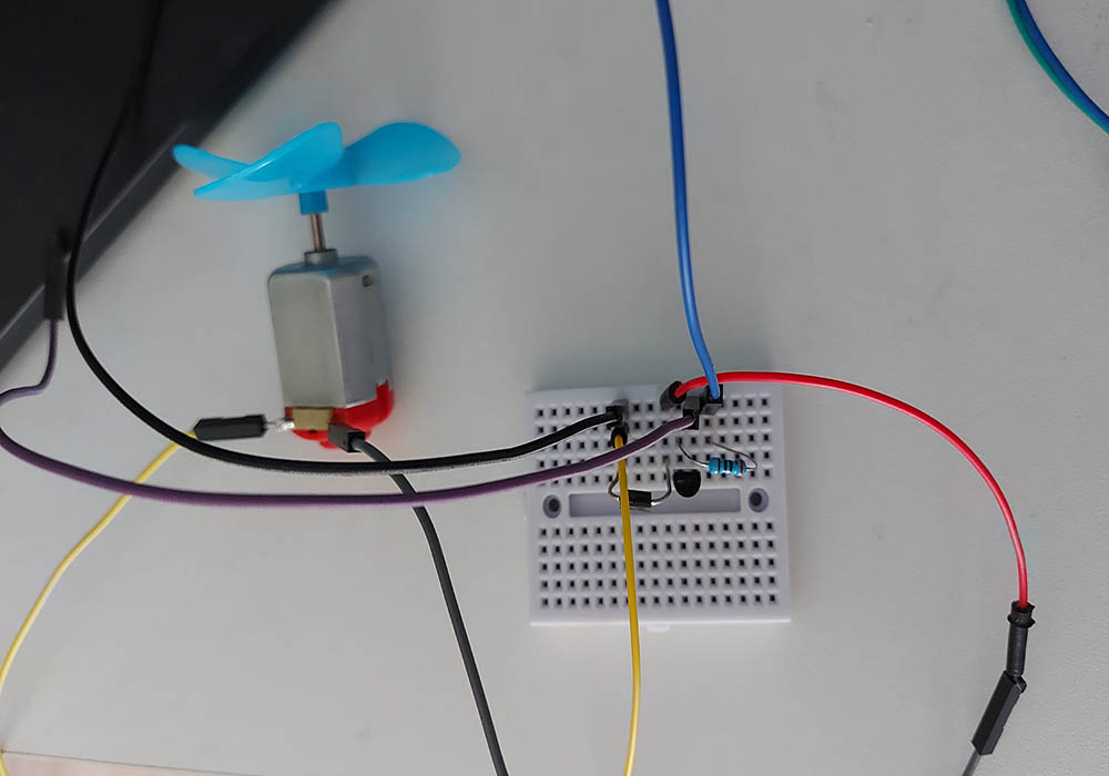
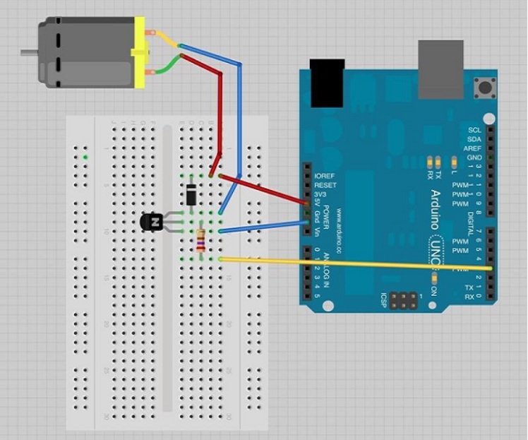 Image taken fromforum.arduino
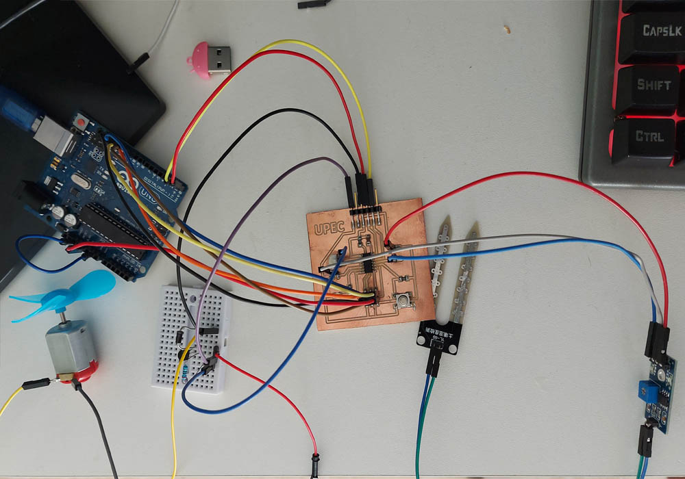
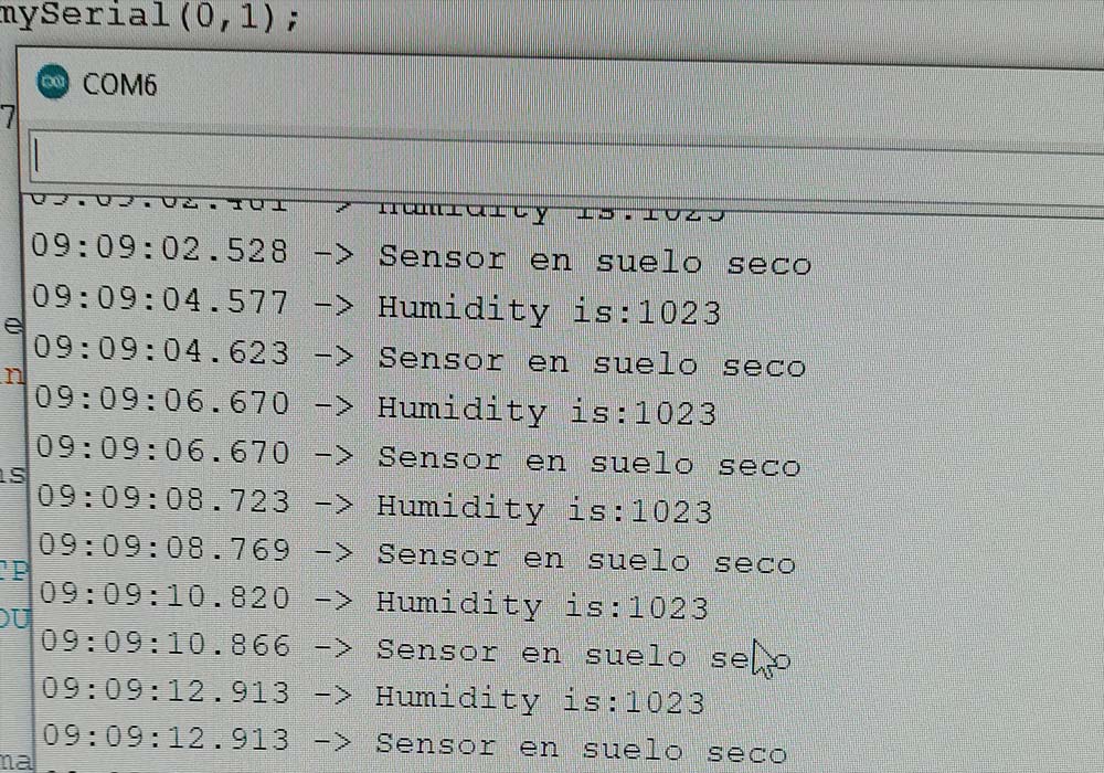 Image taken fromforum.arduino
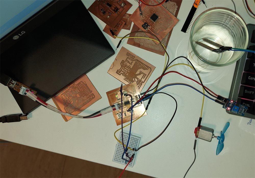
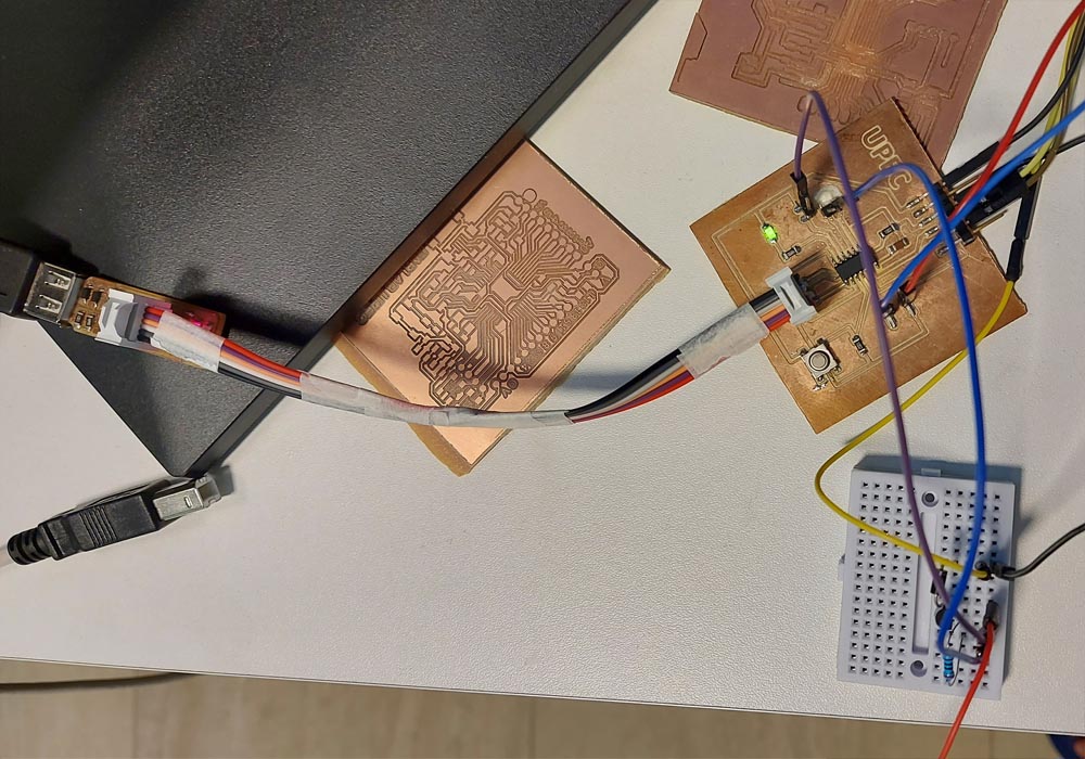
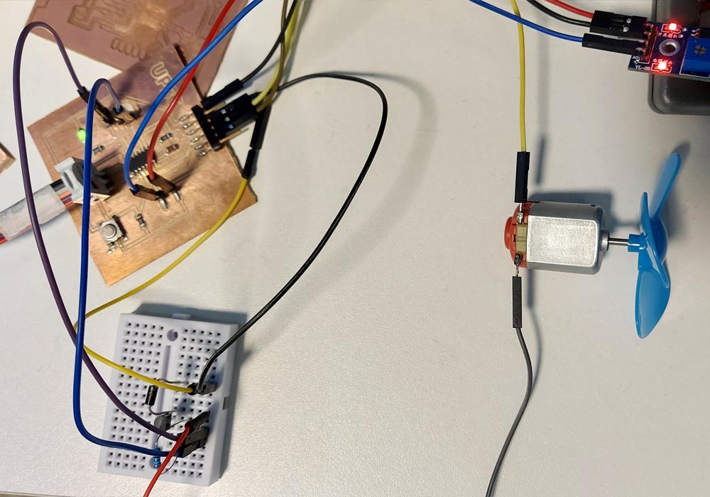
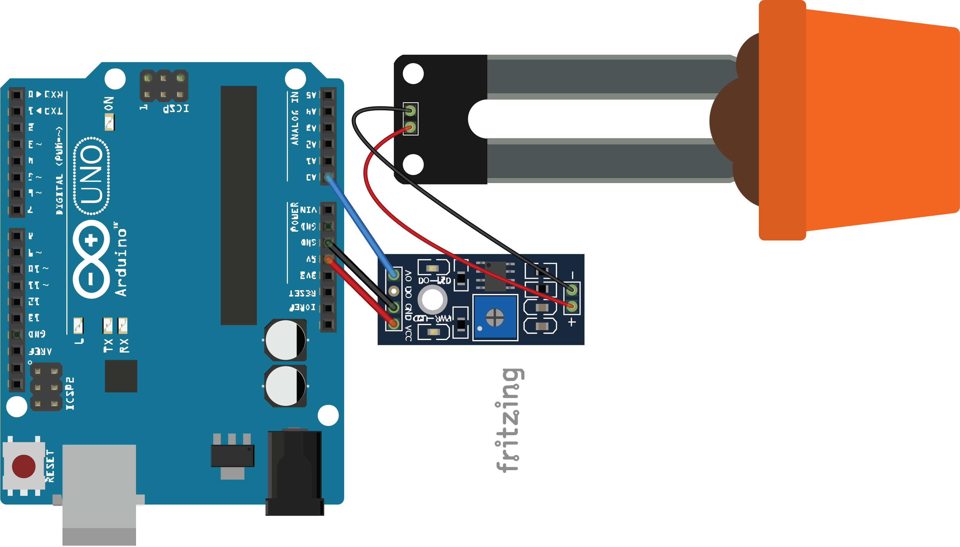 Image taken from automatizacionparatodos
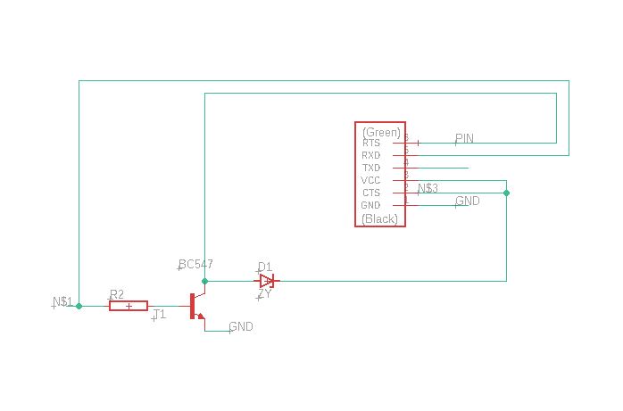
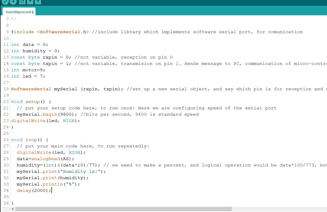
#include
SoftwareSerial mySerial(0,1);
const int LED =7;
const int MOTOR =10;
void setup() {
// put your setup code here, to run once: Here we are configuring speed of the serial port
mySerial.begin(9600); //bits per second, 9600 is standard speed
//pinMode(sensorpin,OUTPUT);
pinMode(LED,OUTPUT);
pinMode(MOTOR,OUTPUT);}
void loop() {
// put your main code here, to run repeatedly:
digitalWrite(LED, HIGH); // enciende el LED
int humidity=analogRead(2);
mySerial.print("Humidity is:");
mySerial.println(humidity);
if(humidity > 760){
mySerial.println("Sensor en suelo seco");
digitalWrite(MOTOR, HIGH);
}else if(humidity < 750){
mySerial.println("Sensor en agua");
digitalWrite(MOTOR, LOW);
}
delay(2000);
}
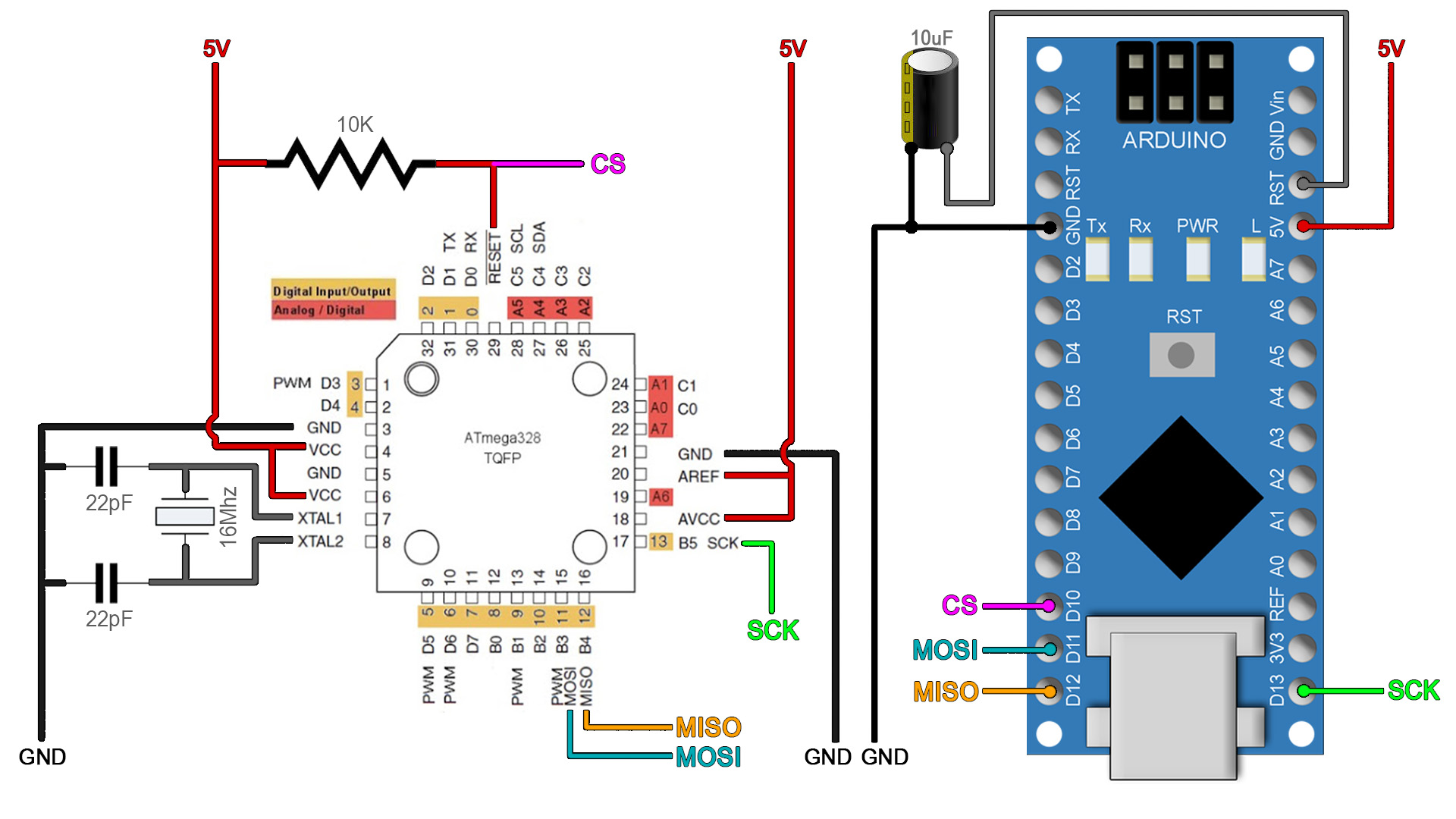
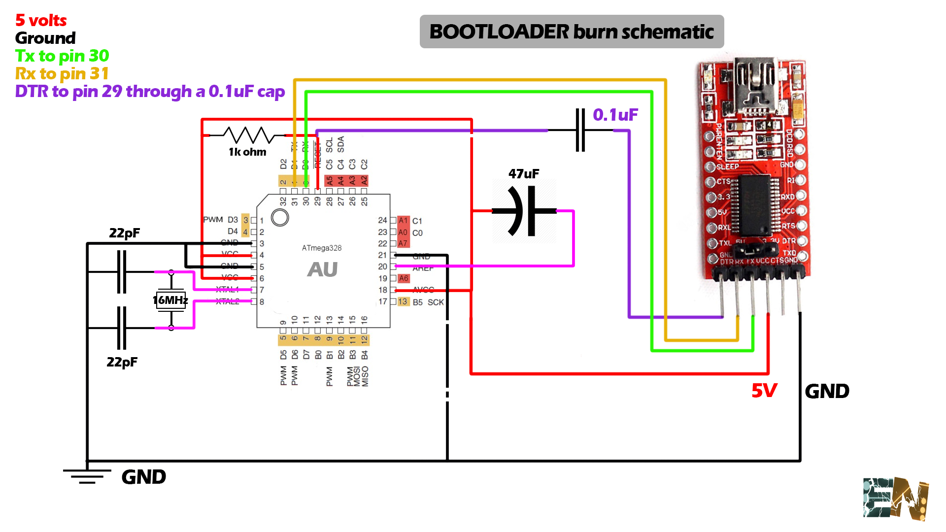
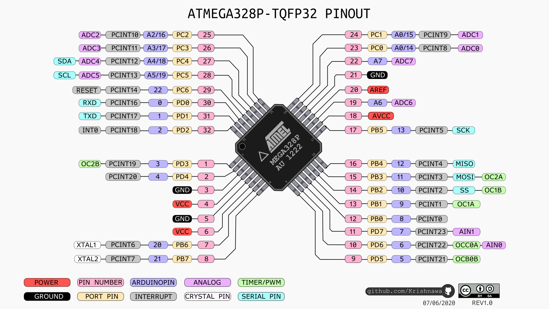 Image taken from electronoobs
 |
 |
|
| Image taken from electronoobs |
 |
 |
| Image taken from electronoobs |
 |
 > > |
This week's work was quite interesting and opened the doors to new ideas and design possibilities that I had not explored before, there is a lot to learn in design tools, but expertise is not learned overnight.
Finally, you have to remember all the safety parameters to make good use of the machines, especially the laser cutter, which can be very dangerous. When it comes to cutting vinyl, it was a lot of fun to be able to make custom stickers, although the job of removing excess material is a bit stressful