Electronics Design

Electronics is associated in the current developments in technology, the way to make the elements commons can make people's lives easier and undoubtedly transforming the society, habits and personality of individuals.

The growing influence of technology on automation and productivity in industry, commerce, banking, certainly in all sectors of the economy. For that reason it can be assured clearly that electronics is a pillar of modern society.

Assignment:

Group assignment

  • use the test equipment in your lab to observe the operation of a microcontroller circuit board

Individual assignments

  • redraw an echo hello-world board, add (at least) a button and LED (with current-limiting resistor) check the design rules, make it, and test it
  • extra credit: simulate its operation..

Using measuring equipment:


The multimeter is not just for checking voltage. By purchasing a multimeter, you are acquiring a powerful and versatile measuring instrument that will allow you to measure voltage and current values. You can generally use it for direct and alternating current measurements and also for resistance measurement.


Oscilloscopes check and display voltage signals as waveforms and as visual representations of voltage variation as a function of time. The signals are plotted on a graph, which shows how the signal changes.


Design a circuit board Using Eagle

It was a practice in TINKERCAD to remember electronics principles, I put together several circuits using an Arduino mega to connect LEDs, sensors and other components.


Eagle is a very powerful tool to carry out the design of electronic circuits, it allows us to incorporate external libraries that contain specific components. You can download this tool from the following link, "download Eagle"you can register with an educational account and download the product

Practice in TINKERCAD


Redraw an echo hello-world board


For this week assignment I designed a board based on Adrian's Hello Train from last year. I find this assignment pretty hard to do from scratch so I ratter follow instrcutions until I understand all the concepts and processes involved. I checked his BOM which has the following components and started from there since I already understand how to insert and connect them on Eagle:


Components

1 - Attiny 1614

1 - Capacitor 1 µF

1 - Button

5 - Resistance 1k

1 - Resistance 499Ω

1 - 2x1 Pin

1 - 6x1 Pin

3 - Led (white) / There weren't avaliable at the lab inventory so I used blue leds

2 - Led (red)

EAGLE Design schematic

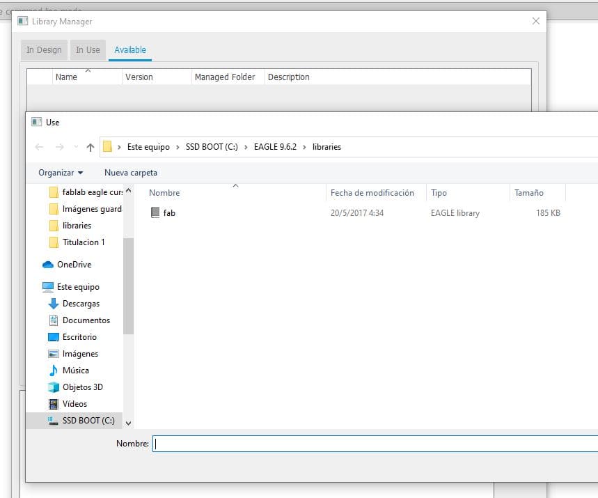
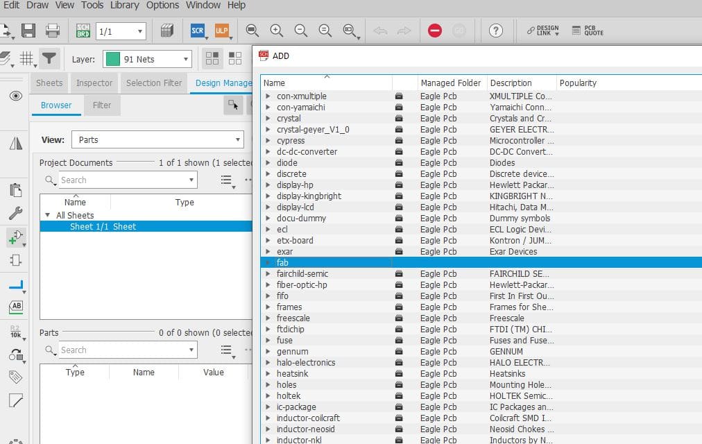
To start with the design, we loaded the Fab component library. it is important to be careful with the parameters of the components as well as their polarities


Making the board


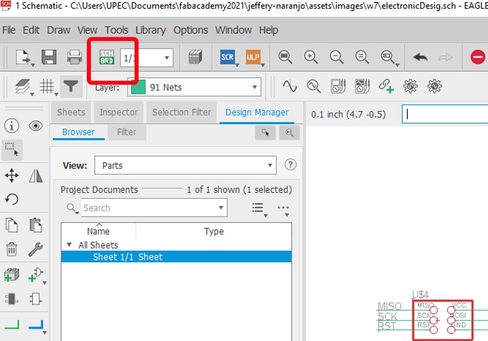
Finished our schematic design, we will proceed to place the components on our pcb board, for this we click on the button, generate switch to board, this will send us to another window where we can see our components but placed in no specific order.


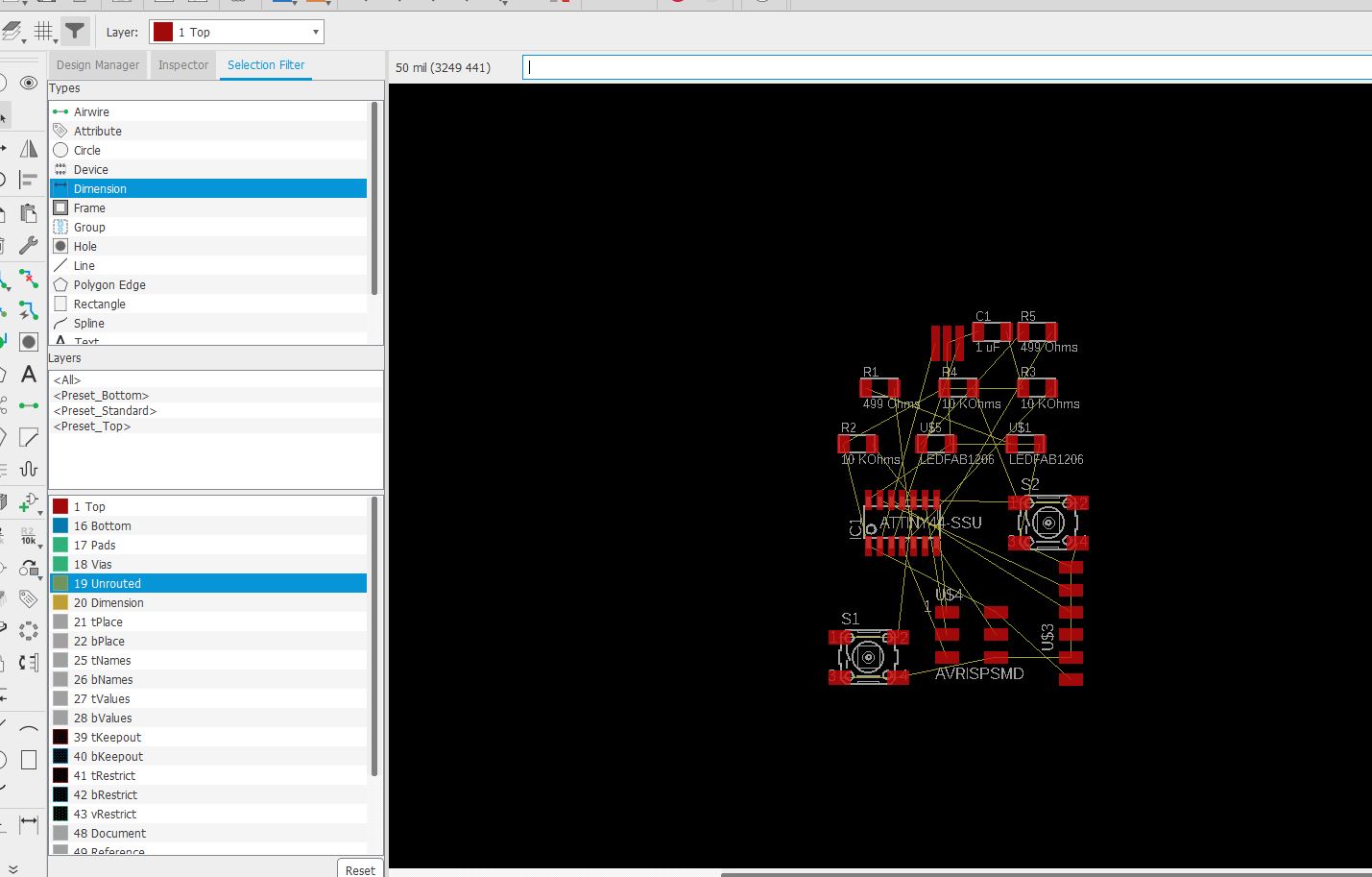
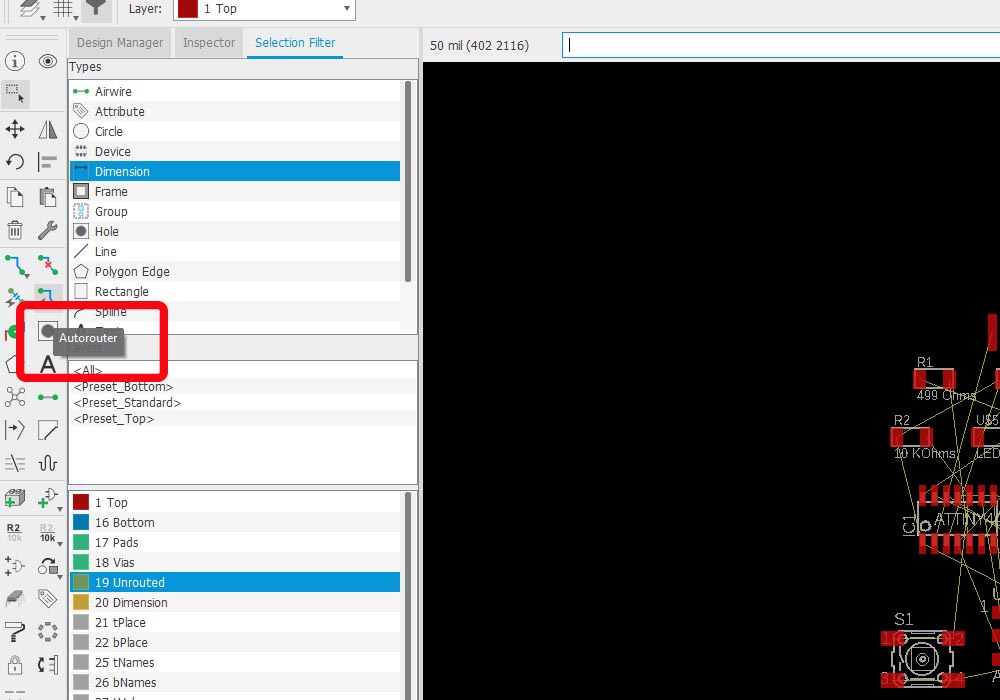
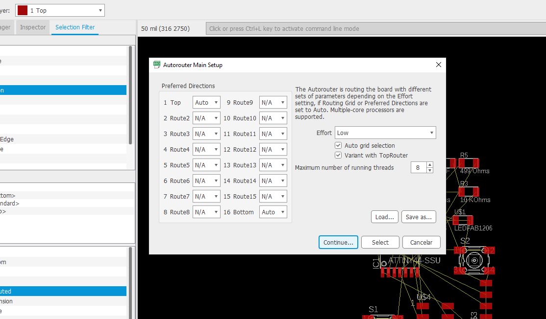
At this point we can use the auto-routing option, but with this we leave it to the machine to make the decisions about where to place the components, and it doesn't always work out well, since it can place tracks behind the board.

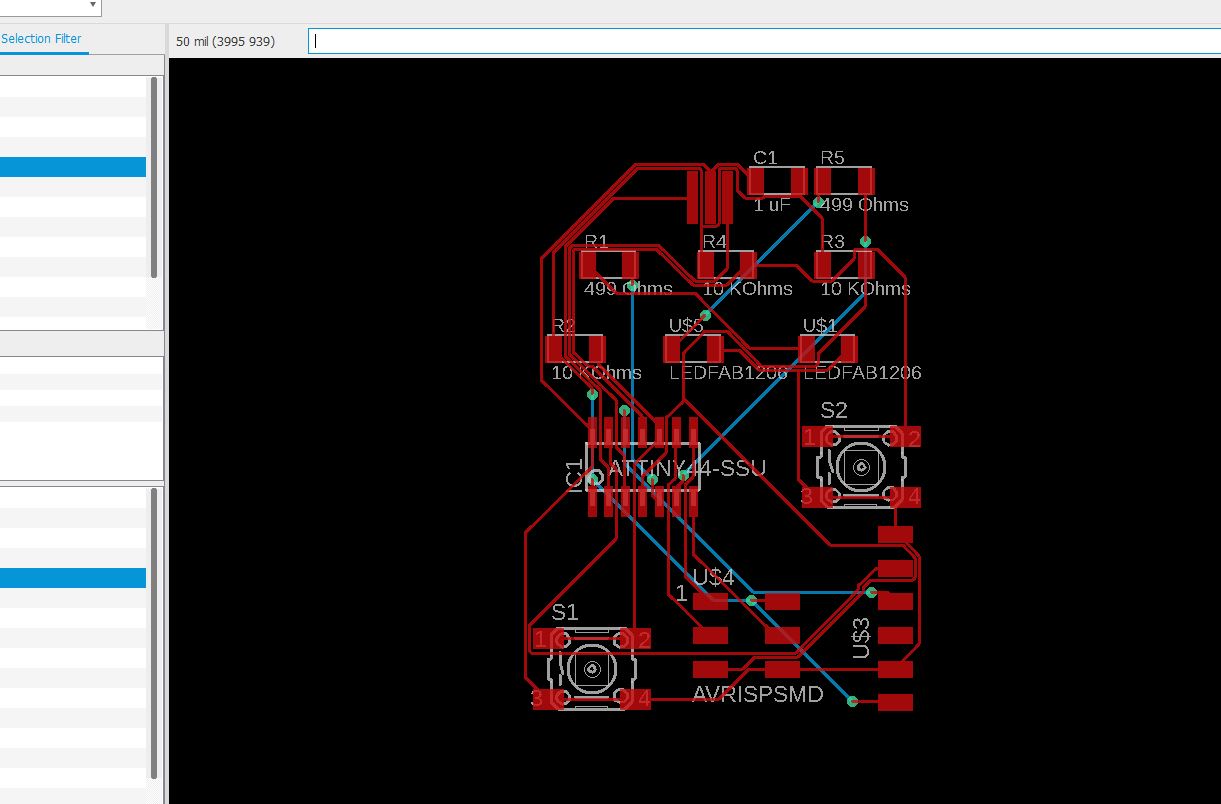
The most recommended is to place each of the elements by hand, and so we can give the design we want to our board


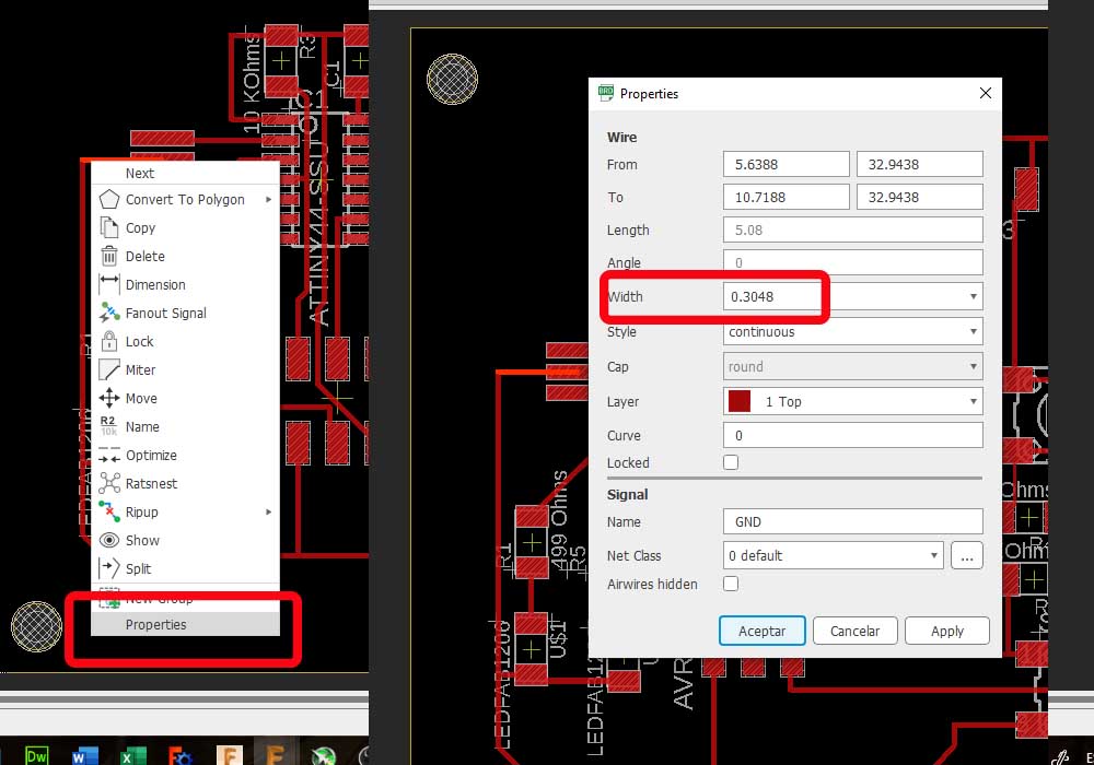
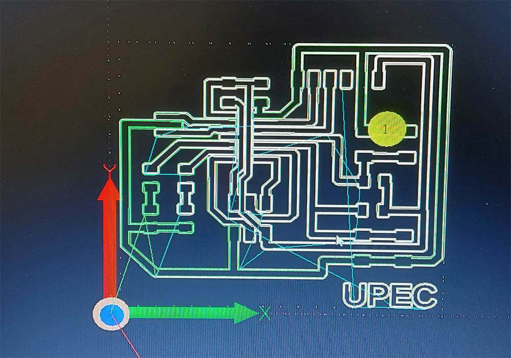
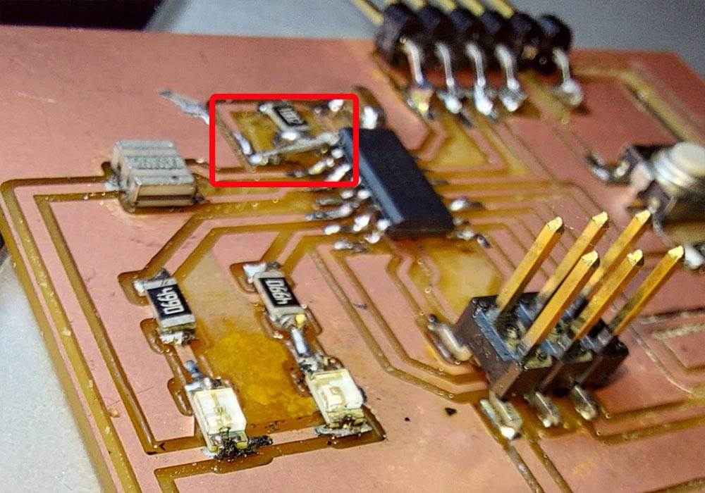
The yellow lines indicate the connections between components, we can also place each of the components in layers, it is important to give an adequate thickness of the traces, if we make them very thin, the safest thing is that they come off when welding.

We can change the thickness of the tracks by right clicking properties and changing the value
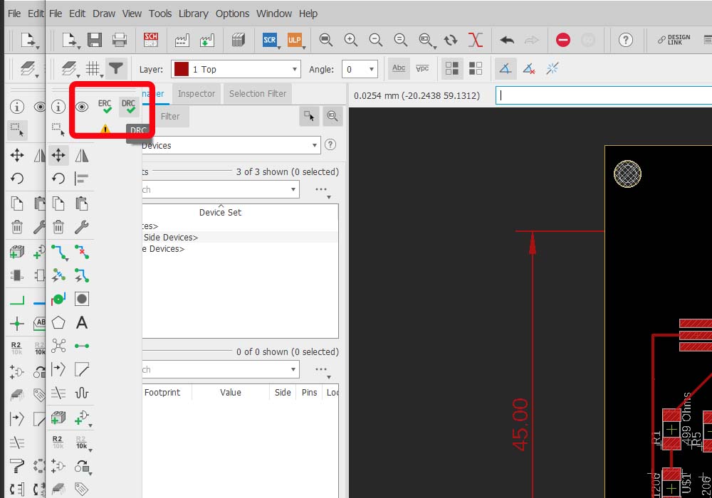
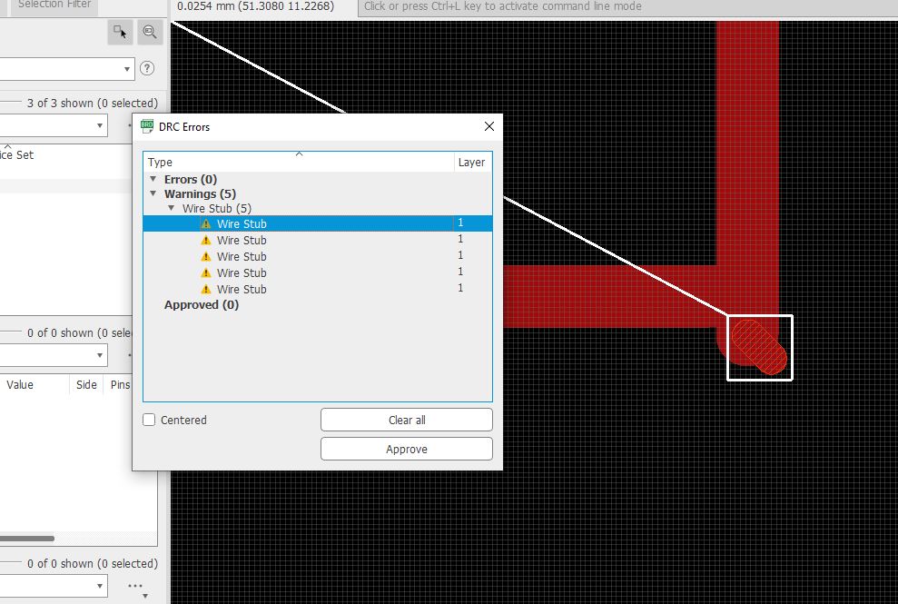


Design rules (DRC)


One of the tools that Eagle provides us, is an option called DRC (design rule verification) this tool warns us about space and design problems that could affect the production of our pcb circuit board.


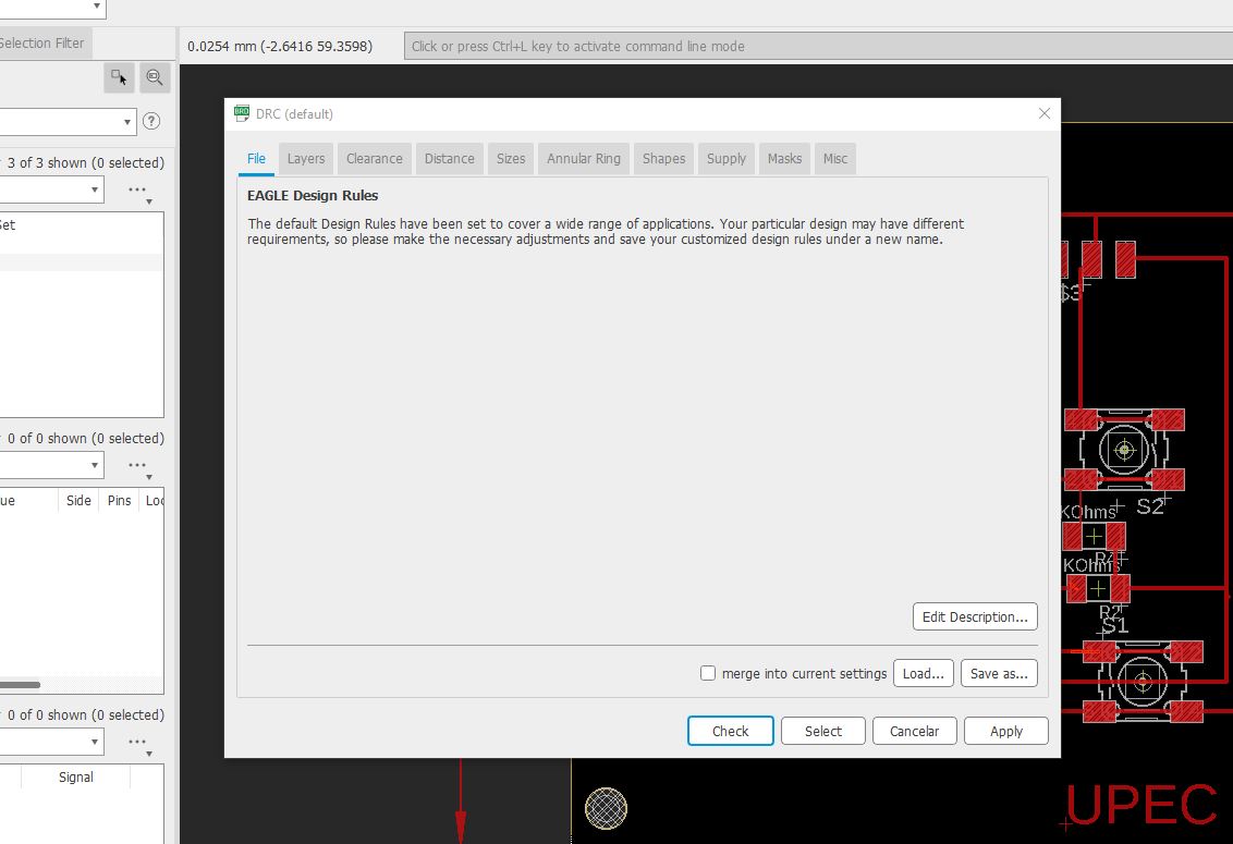
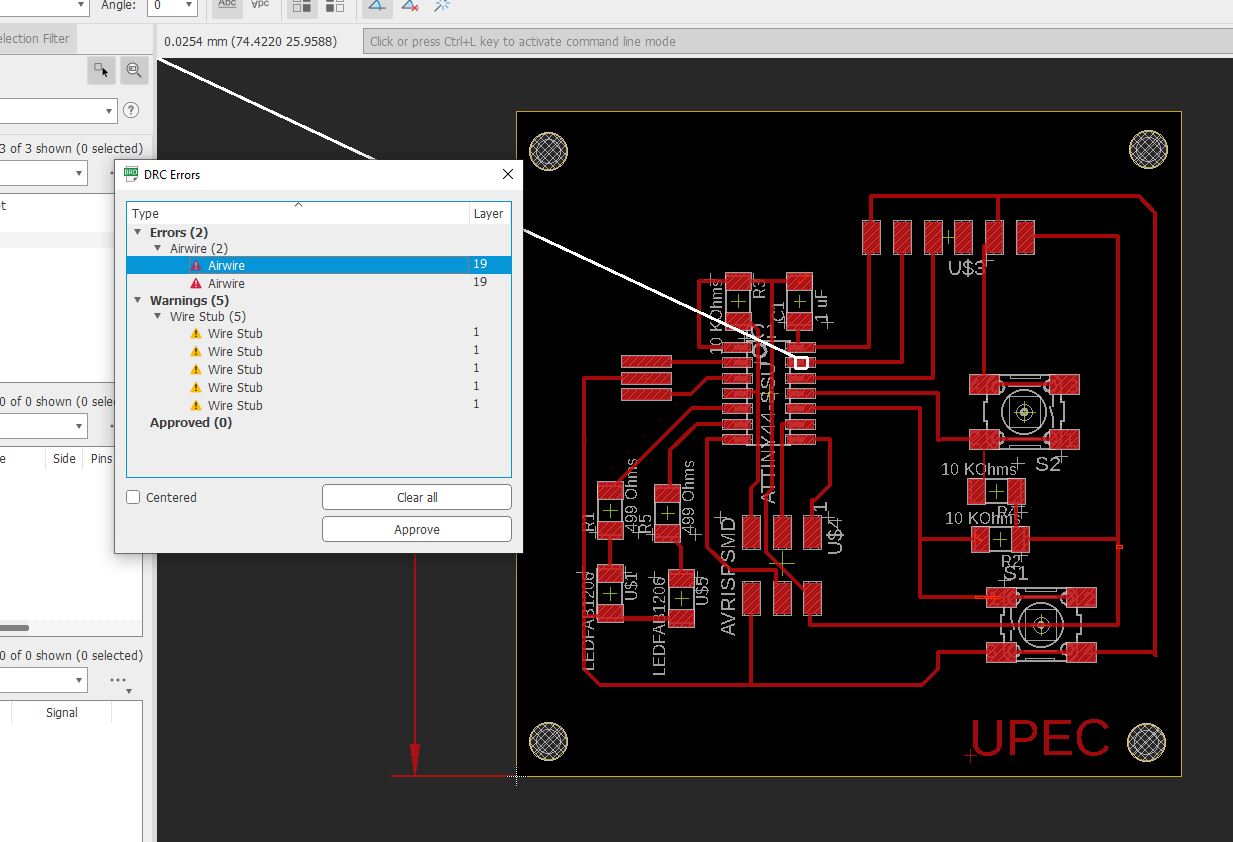
Once the tool is executed, we click on the check button, this opens a pop-up window, it shows us the errors and warnings, clicking on them, takes us to the exact part where the problem is found, in this way we can delete the line or correct its trajectory and / or thickness to eliminate the error


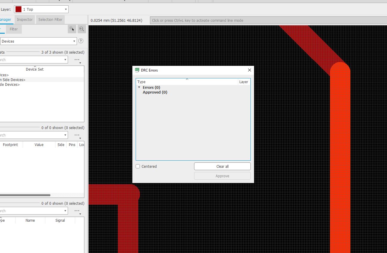
once the corrections are finished we will have an indication that we no longer have errors or warnings we can save the Design Rules Check File
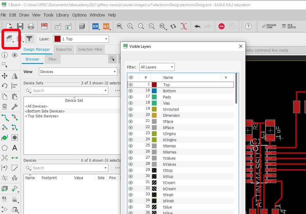
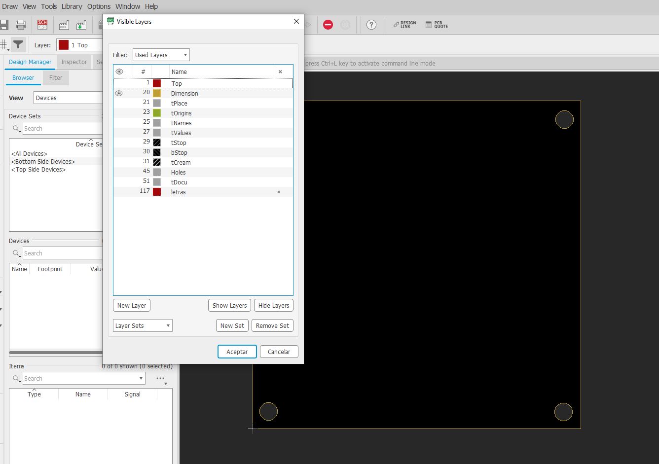


Here you can download the Design Rules Check File


Exporting PNG file


Before exporting our file we are going to hide all the layers and leave only the tracers layer on


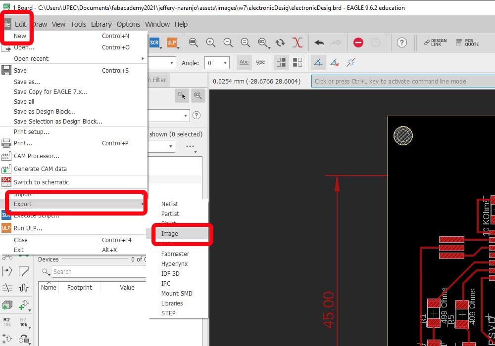
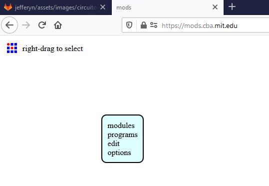
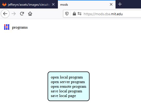
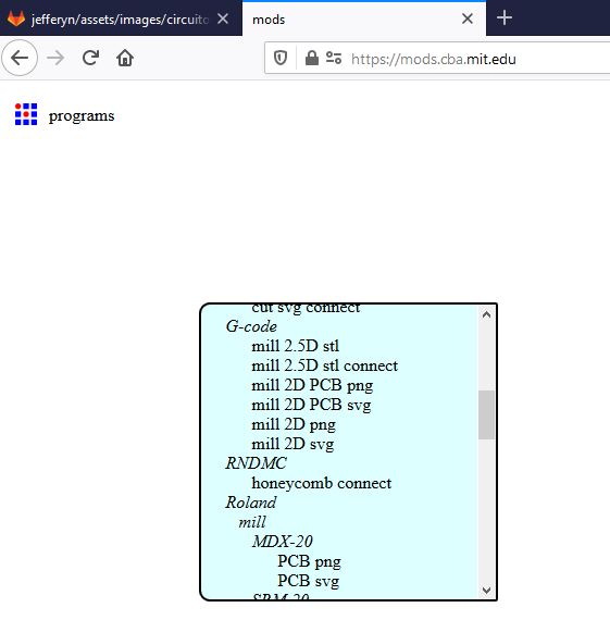
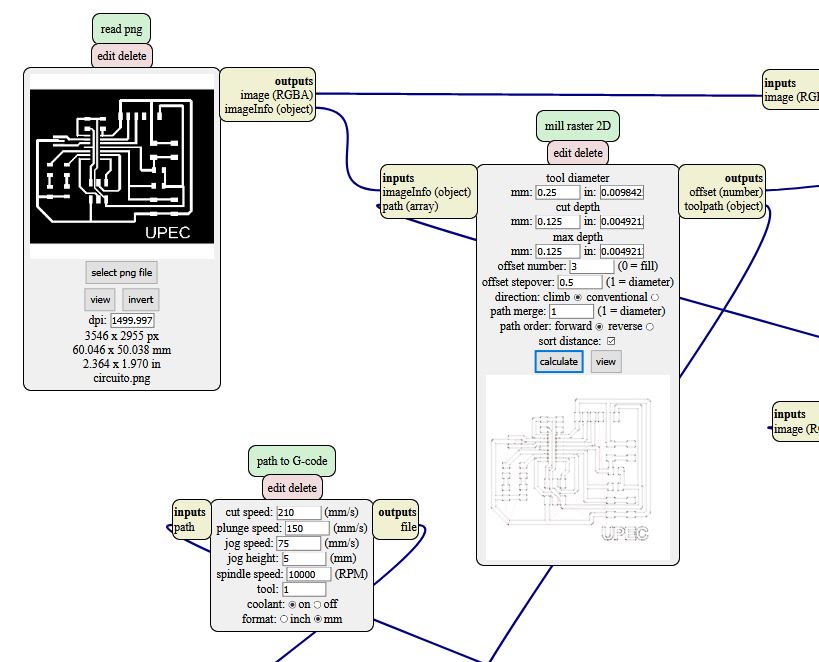
Finally, to export our work in PNG format in order to generate the G-codes through MODS, we go to the toolbar, export, image. 
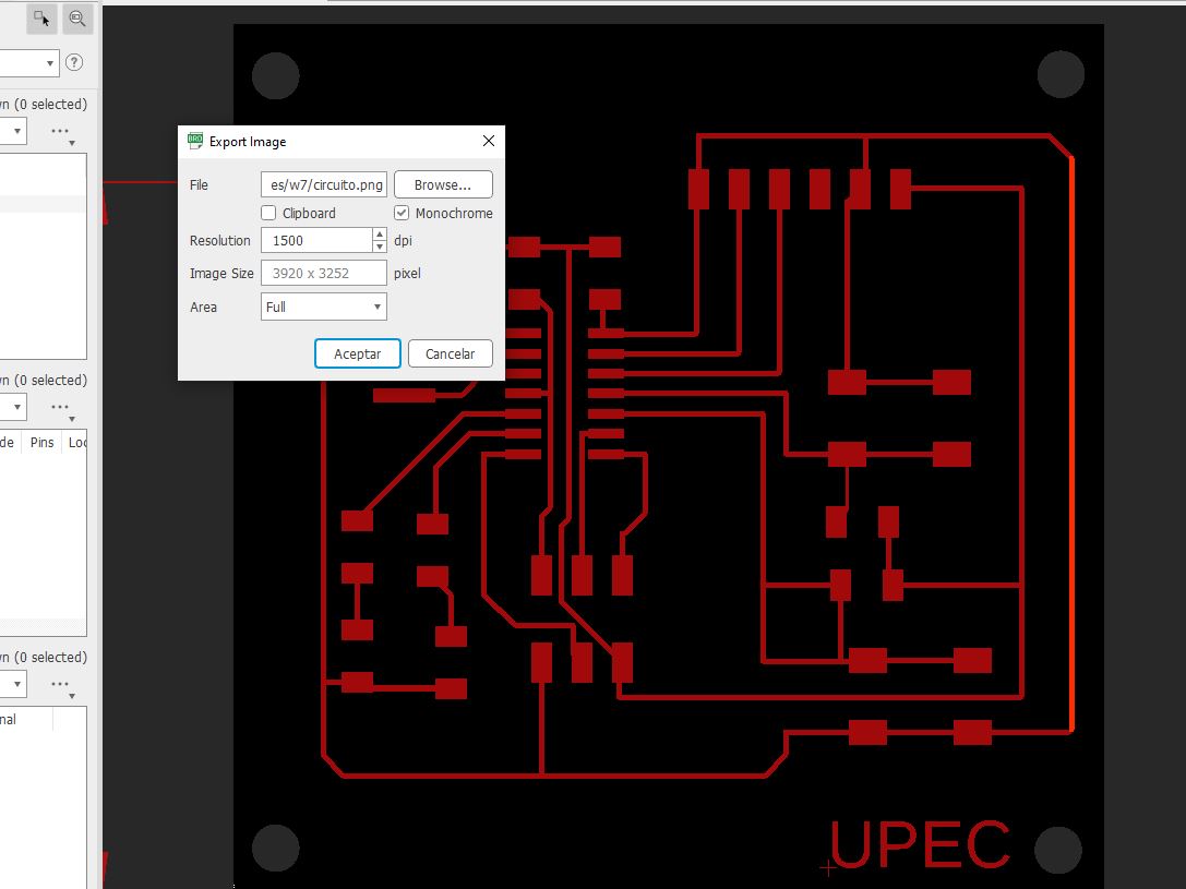
Here there will be a pop-up window where we will indicate the place where we will save our image, we will indicate the resolution, here it is recommended 1500 dpi

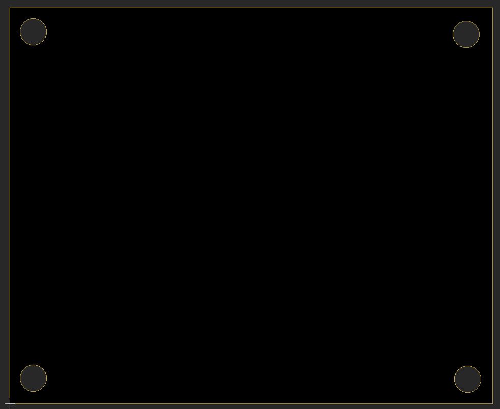
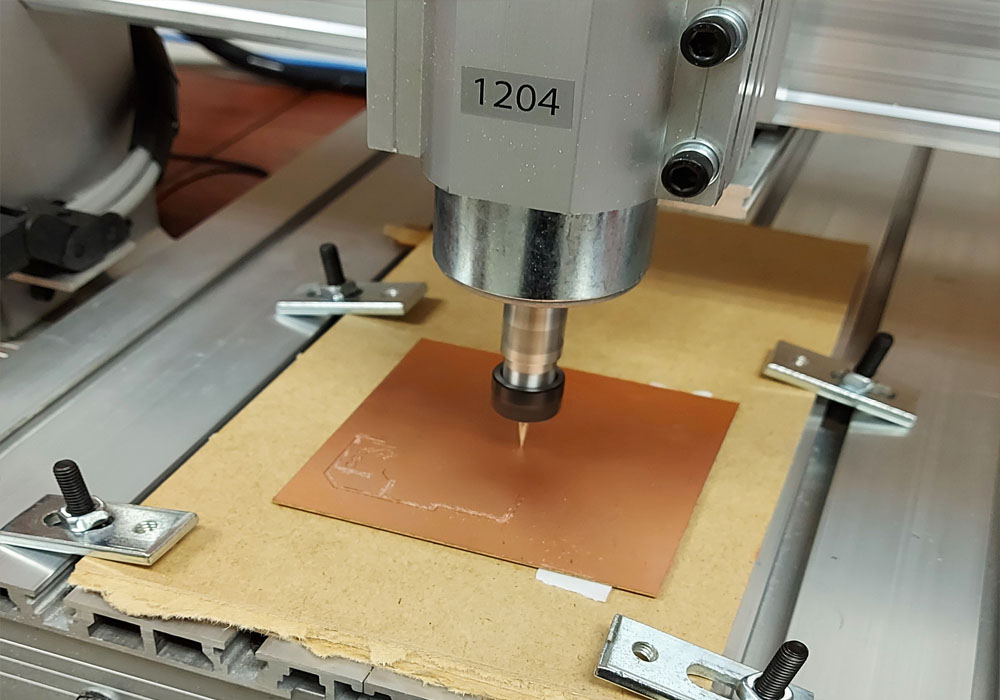
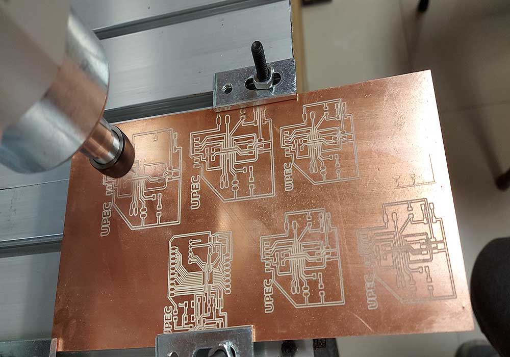
We will use the same procedure to cut the outline, the holes, etc.


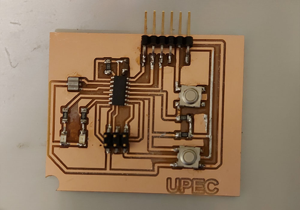
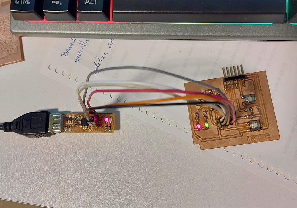
Now we will see some images with the final result of the generation of the files


Eagle File download


Milling the board


We will use the online tool Mods to generate our G-code, we can see the complete procedure in the electronic production assignment in the following link Electronic production


Once the G-code mill 2D png options have been chosen, we will proceed to configure the options to perform the milling of our pcb board


File download


checking our file with g code simulator


Preparing and soldering the electronic board

for the creation of the pcb board we use the Cnc software USb controller


To start with the use of the cnc it is necessary to calibrate it first, for this we will make it travel a distance in millim on the 3 axes and we will measure the real distance traveled, we will carry out this procedure several times until the indicated distance is equal to the distance traveled.


Once the calibration is finished, we start the manufacture of the pcb board, we simply load the G-code file to the Cnc Usb Controller, more details can be found in the following link of the week of Electronic production


Through the G-codes we can manufacture plates practically in series with the help of our cnc, Finally with the finished pcb board we proceed to solder the elements in their respective places


Resolving pcb board errors


The recommendation is to buy a pcb board of the best quality, this will prevent the tracks from lifting or breaking at the time of soldering, if this happens we can solder bridges to join the component to the track


The circuit


Testing electronic board

To prove that the electrical circuit board is well made, the welds of the elements were checked, then a simple program was loaded with a loop that turns a led on and off, this was done through the programmer created in the week of electronic production. , an Arduino was also used to carry out the programming and verify the communication between elements


General Conclusion:


  • A good design and placement of the elements, the appropriate parameters for the cnc introduced in the Mods, will help us to manufacture a good plate and in this way we can weld the components without fear of circuits, of course the help of a microscope makes a precision and quality work.

    It is very important to carry out the calibration of the cnc, some correct adjustments will help us to make a good printed circuit


  • Return