Networking and Communications
Group assignment:
Individual assignment:

The I2C communication bus helps us to implement it very easily in many electronic designs that require communication between a master and multiple slave devices or even multiple master devices. Its easy implementation is due to the fact that it helps us that by means of and the use of two cables for communication we can connect between up to almost 128 (112) devices. when we use 7-bit addressing and up to almost 1024 (1008) devices when using 10-bit addressing.
Each I2C bus can support up to 112 devices. All devices need to share GND. The speed is around 100 kb/s—not very fast but still respectable and quite useable. It is possible to have more than one master on a bus, but it's really complicated and generally avoided. A lot of sensors use I2C to communicate, typically Inertial Measurement Units, barometers, temperature sensors, and some Sonars. Remember that I2C is not designed for long cable lengths. Depending on the cable type used, 2 m might already cause problems. Connecting more devices If we need to connect more than two devices on an I2C bus, we just have to connect all SDA and SCL lines together. We will need the address of every slave to be addressed from the master Arduino.
Only uses two wires Supports multiple masters and multiple slaves ACK/NACK bit gives confirmation that each frame is transferred successfully Hardware is less complicated than with UARTs Well known and widely used protocol
Slower data transfer rate than SPI The size of the data frame is limited to 8 bits More complicated hardware needed to implement than SPI. We have connected micro controller, so these steps to connect two Arduinos using I2C: First step Connect pin A4 and pin A5 on one Arduino to At mega 25600 pin 20 SDA , and pin 21 SCL . Second Step the GND line must be common for both Arduinos. Connect it with a jumper. Third Step Remember never to connect 5 V and 3.3 V Arduinos together. It won't hurt the 5V Arduino, but it will certainly annoy its 3.3 V.
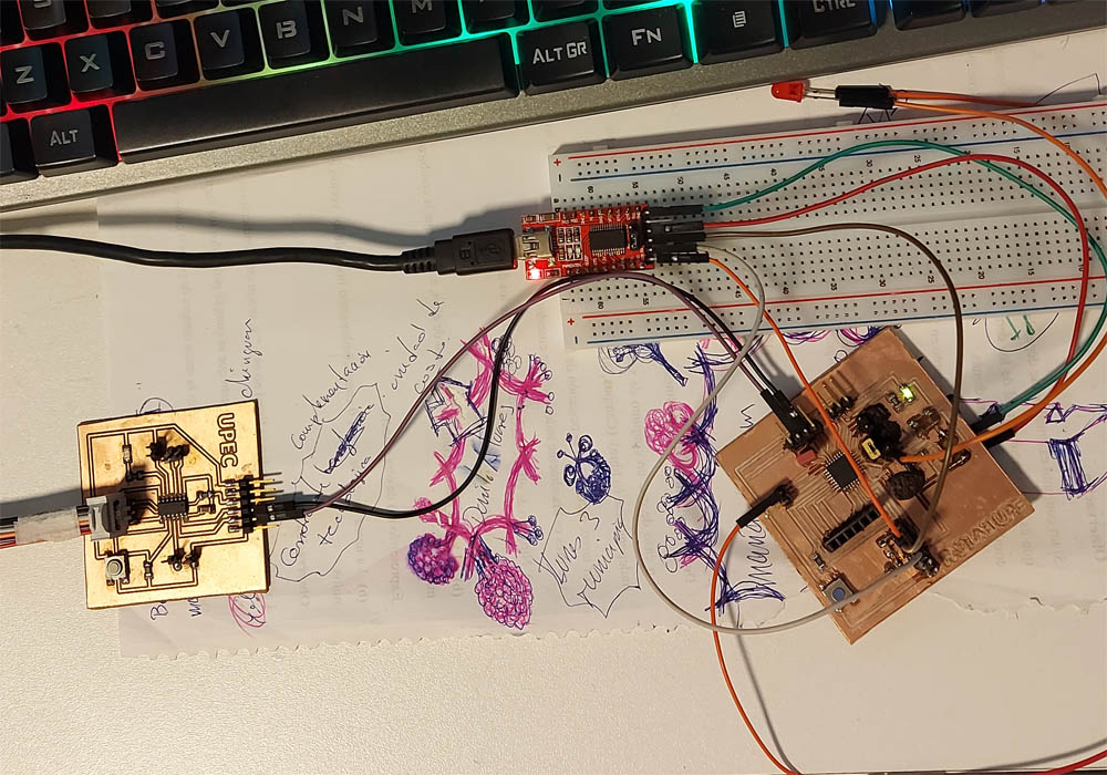
 Image taken from circuitdigest
 Image taken from circuitdigest
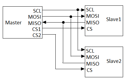 Image taken from signoffsemi
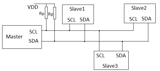 Image taken from signoffsemi
 |
 |
| Image taken from circuitos-electricos |
 |
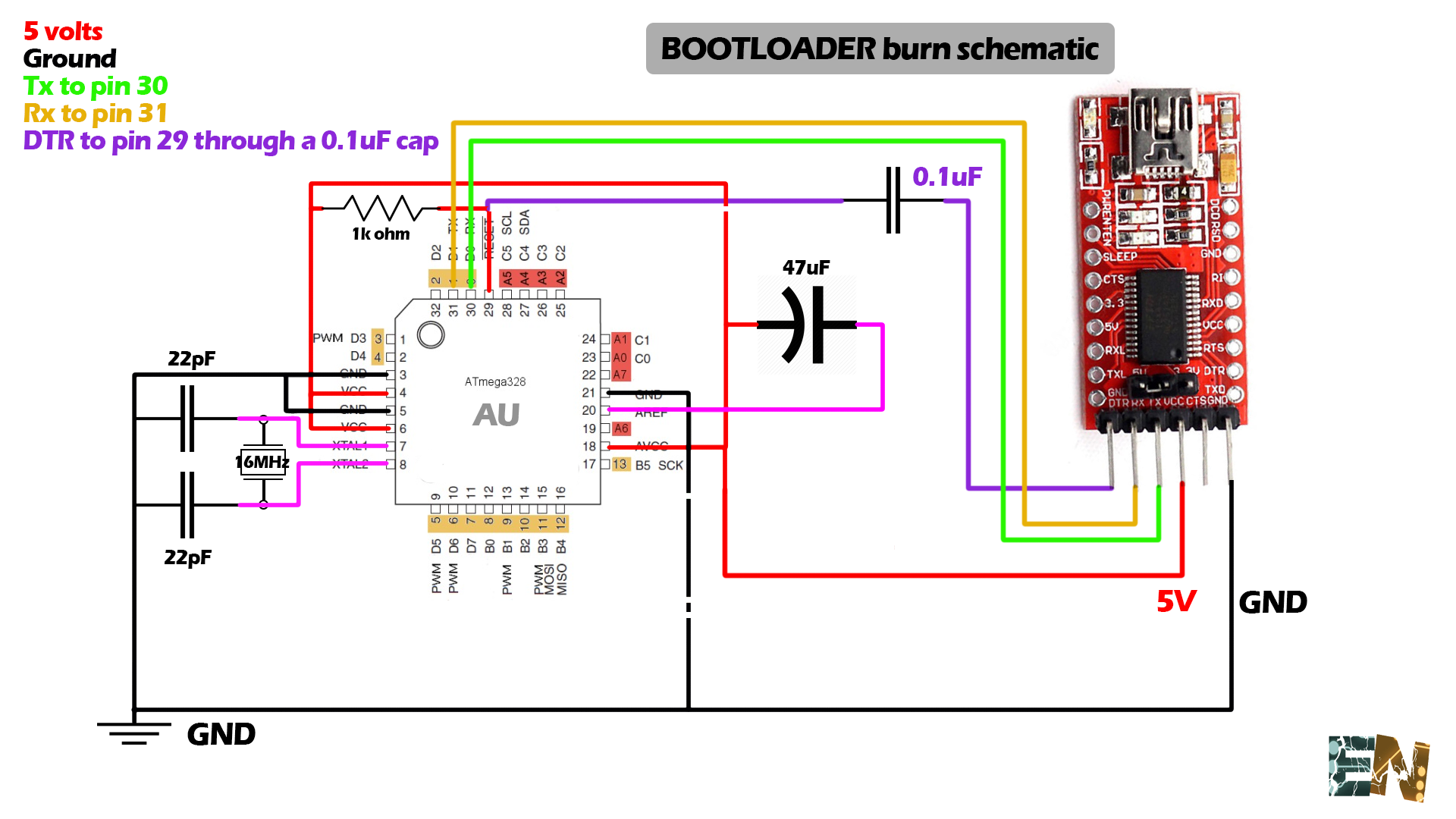 |
| Image taken from electronoobs |
 |
 |
| Image taken from prometec |
This week's work was quite interesting and opened the doors to new ideas and design possibilities that I had not explored before, there is a lot to learn in design tools, but expertise is not learned overnight.
Finally, you have to remember all the safety parameters to make good use of the machines, especially the laser cutter, which can be very dangerous. When it comes to cutting vinyl, it was a lot of fun to be able to make custom stickers, although the job of removing excess material is a bit stressful