Find out the details of our common work al ZOI
Here.
Some basic concepts to star from, to understand what we are about to face:
- CNC (computer numerical control) machining is a process in manufacturing where programmed computer software
directs the motions of plant machinery and tools.
- Is the process of removing material from a workpiece until the desired shape is configured.
- There is a wide range of applications: milling, water jet cutting, and laser cutting materials.
- CAD files transfer a precise set of sequential instructions
- There are many benefits: expense reduction, improved speed, better accuracy, and enhanced productivity levels.
- This machines operates in at least 3 axes along an XYZ plane: X axis (vertical), Y axis (horizontal),
and a Z axis (depth).
- The 4th axis denotes the inclusion of an A axis (rotation around the X axis), and the 5th
axis denotes the B axis (rotation around the Y axis).
- The number of axes on a CNC machine determines the type of work it can do, the level of detail it can cut,
and the workpiece locations it can manipulate.
LAB's cnc machine
The machine avaliable at the lab was the following characteristics:
- Model: 1325, 3 axes
- Working area:1300x2500x200mm
- Software:Artcam and

THE DESIGN PROCESS
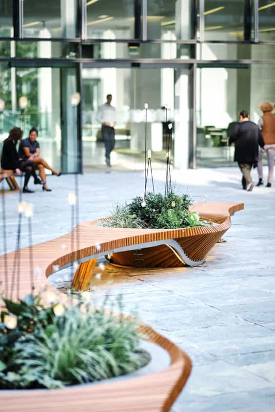
For this week assignment I wanted to do something I could use at home, and one of the things I need
the most is seating space because my apartment es not too big. I also wanted to do something I could
design using grasshopper and that could work for my final project. These are some of the ideas I looked for inspiration.

This is a resume and evolutions of the ideas that came out during the design process:
It started as "something big", so big that it couln't fit in my appartment, so I reduced it to a stool size.
To be parametric I used the following algorithm where you can change the number of segments, the material width, separation
among segments and finally subtract the perpendicular piece used to hold the segments together, also modifying
its width.
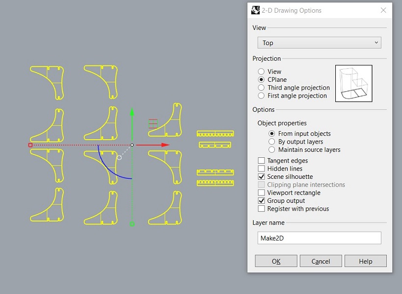
When the 3D model is ready you can bake it in Grasshopper and get the final objects in Rhino. I separated this 3D pieces and lay them flat to generate the 2D.
To do this you have to select the pieces and type make 2D, chose the top view, CPlane and ok, automatically you have your 3d pieces turned into 2D.
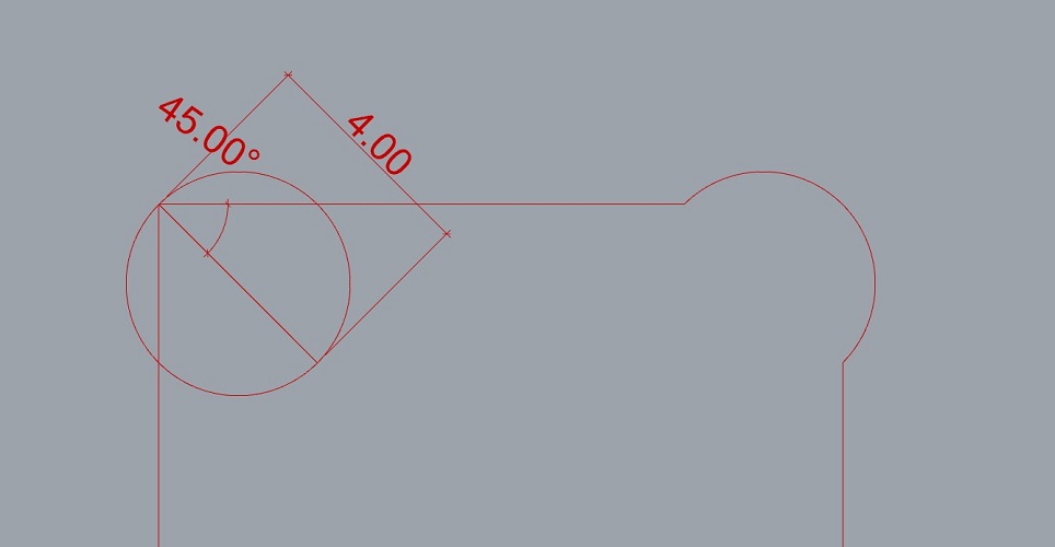
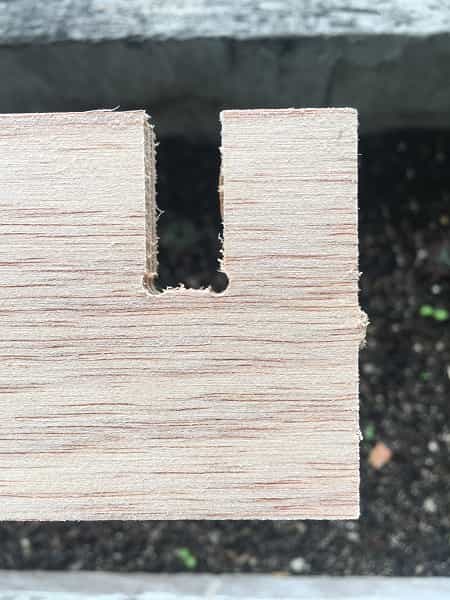
It is important to mention that as part of the design, dog bones must be integrated to assemble the pieces.
Dog bones are cuts that are made in the internal corners of the pieces that must fit with each other, they allow to have a complete scope of the pieces since when
using round burs it is impossible to generate internal angles of 90 degrees. In this case I used dog bone fillet, which is the one that generates more discreet
results when joining the pieces. To carry out this detail, a line must be made to measure the radius of the cutter, in this case I will use a 4mm one, for which
I drew a 2mm line, placed it in the corner at 45 degrees and draw a circle with that radius, deleted leftover lines.
The following video shows how various dog bones can be performed step by step. Very usefull for any design
Design for CNC joinery
files
Rhino file.
Grasshopper file.
Dxf file (cutting file).
Test
The design is almost ready to be produced, but first I needed to do a test with the material width
and try to fit the pieces perpedicular together.
I downloaded the file from Dani's repository (Dani is a former student) and edit it for 12mm plywood.
You can find this file Here.
- Measure the material (12mm plywood, 1200 x 2400 mm)
- There is a slight difference between the thickness of the beginning and the thickness of the end of the board.
This is a normal phenomenon, especially when working with living matter such as wood, which tends to contract
and expand according to environmental conditions. This step is very important as it allows us to keep in mind
considerations for the cutting parameters and also the design. Fortunately, the difference in measurements is
not so great, which allowed me to work with an average to be sure of the cut.
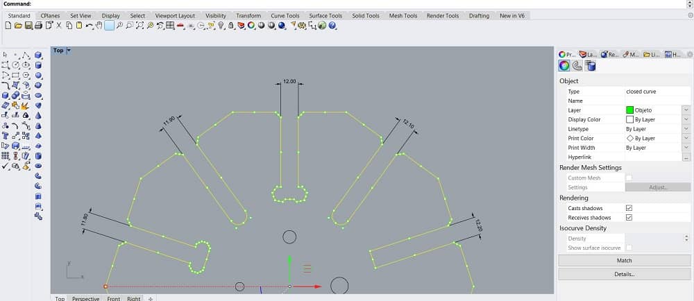
- Modify the file and adapt it to the new considerations. Scale it to fit the internal section to 12mm,
and increase the separation by 0.1mm each to the right and -0.1mm to the left, as shown bellow:
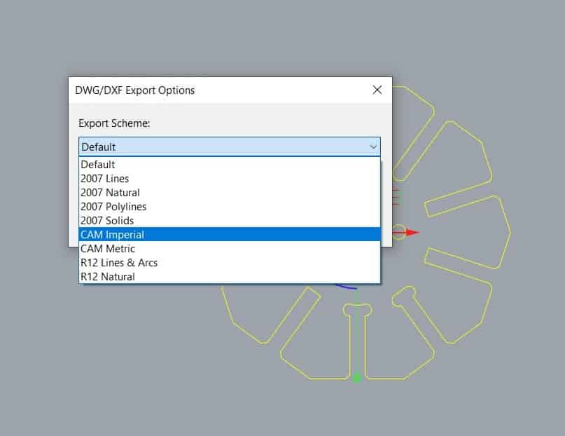
- Select the pieces and export as .dwf and select CAM Imperial
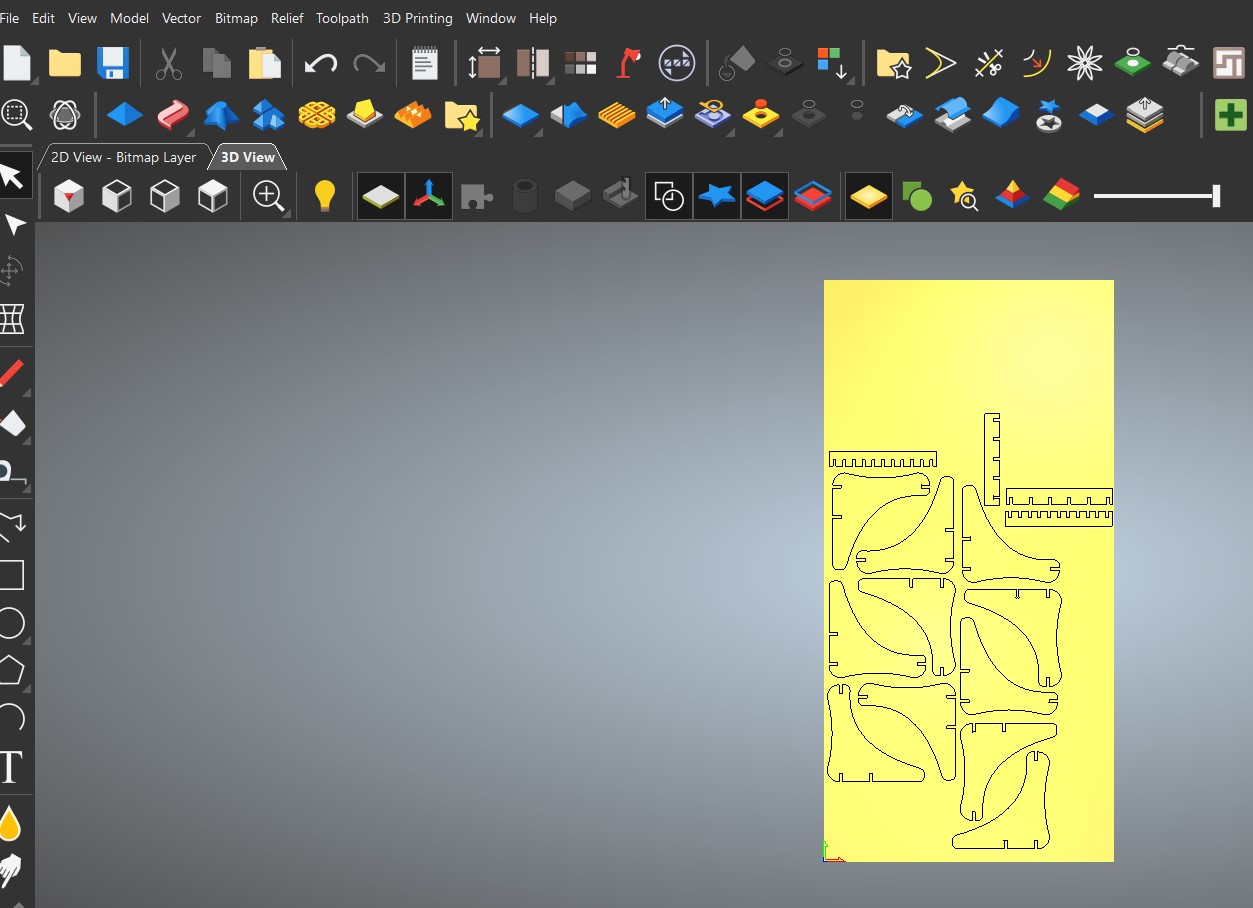
ArtCAM WORKFLOW
Now that we know the material we have to set the file for cutting. In this case we used ArtCAM which is a
CAM (Computer-aided manufacturing) software. Good for working in manufacturing, especially with wood engraving
machines or similar.
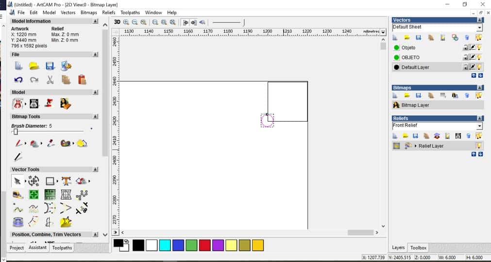
- Open Art CAM and load the file. Vectors>Load
- Select .dxf file and open
- Place the screws in the drawing. For this we drew a 20x20mm square and place it in the corners with a 4mm diameter
circle that represents the screws.
- Go to drilling options to set the parameters for the screws
- Start depth:0
- Finish depth:12.6 (because the material on it widthest part is 12.4, to be sure it cuts we increased it a bit.
- Machine safe z: 30 (this is where the end mill moves from one point to other without toching the material.
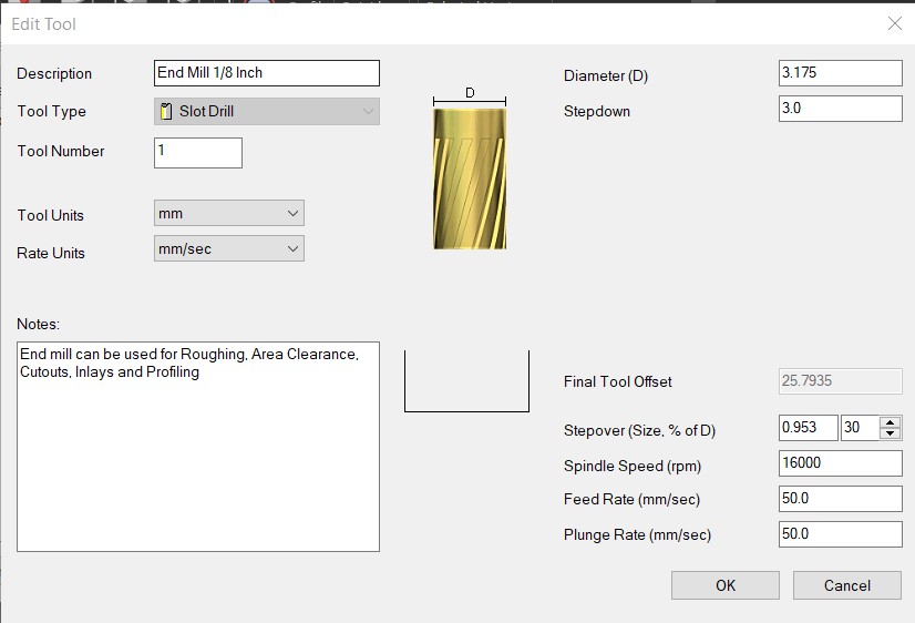
- Tool: select> routing and 2D finish> End mill 1/8 inch ZOI step over
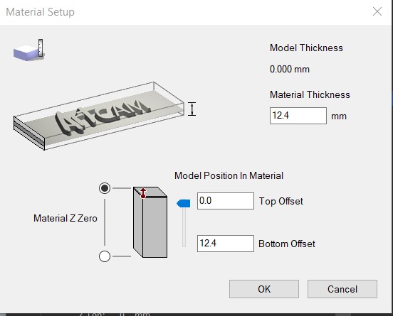
- Material: setup> material thickness: 12.4mm > Model position in material: top offset: 0, bottom offset: 12.4mm. This depends on the material.

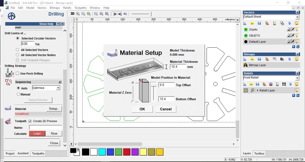
- Toolpath: name> now> write name
- Go to Profiling options to set everything for the pieces
- Prolifing tool: routing and 2D finish> End mill 1/8 inch ZOI step over
- Toolpath: name> now> write name
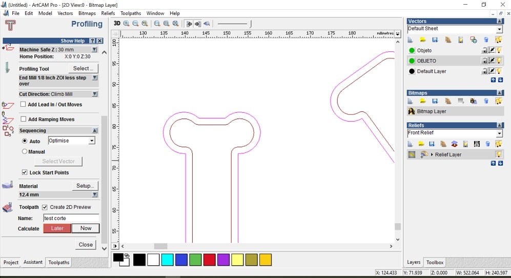
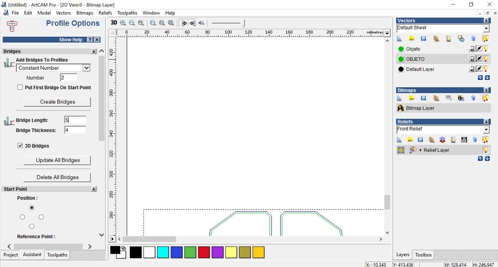
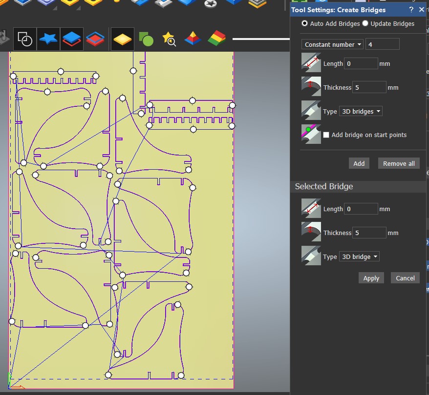
- Profile options: to locate bridges to hold the pieces while cutting
- Add bridges to profiles. Number: 2
- Bridge length: 5
- Bridge thickness: 2
- Double click on the model where you want to locate the bridges
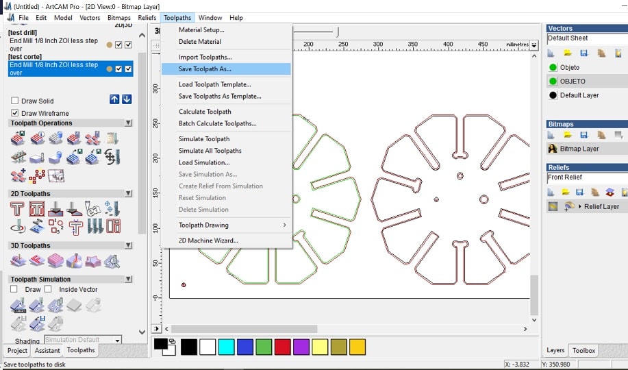
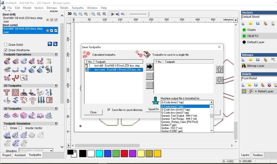
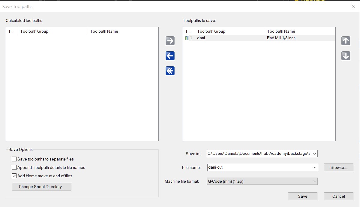
- Save the file: Toolpath> save toolpath as
- Select from the list on the left and push them to the right. Here you will find all the instructions you will send to the cnc machine.
FILES
Fitting test.
CNC WORKFLOW
With the .tap file ready we can prepare everything to cut
- Place the board on the cutting bed. The machie we are using is the CNC Router 1325.

- Remove the nozzle to place the collet and the end mill we need for this work.

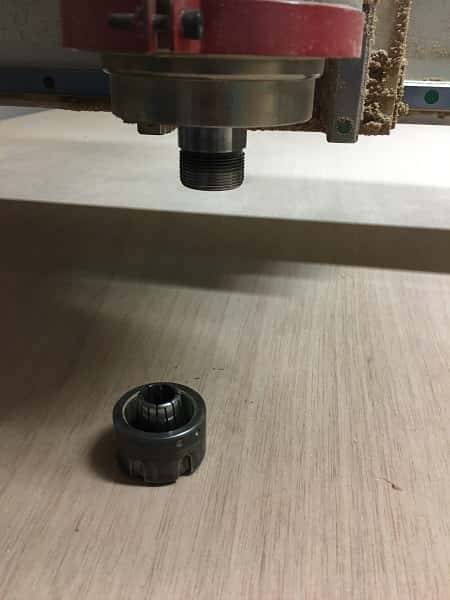
In this case we used a flat head 1/8" mill. Make sure the collet and end mill are in the same units (mm o inches)

- Copy the file on a designated folder
- Open the software
- Open the file for the drilling
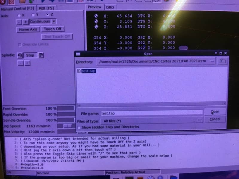
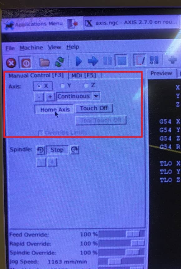
- Use the keyboard to set 0 for x, y and z
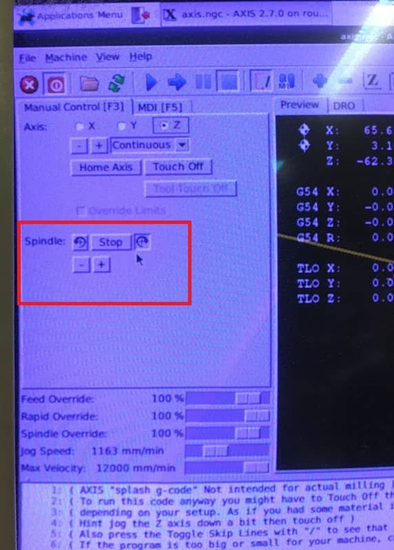
- Turnon the spindle
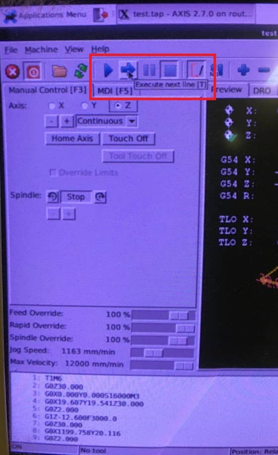
- To run the code step by step you can press "T" and to do it non stop press "S"
- Once the drilling holes are ready, put the screws to hold the material

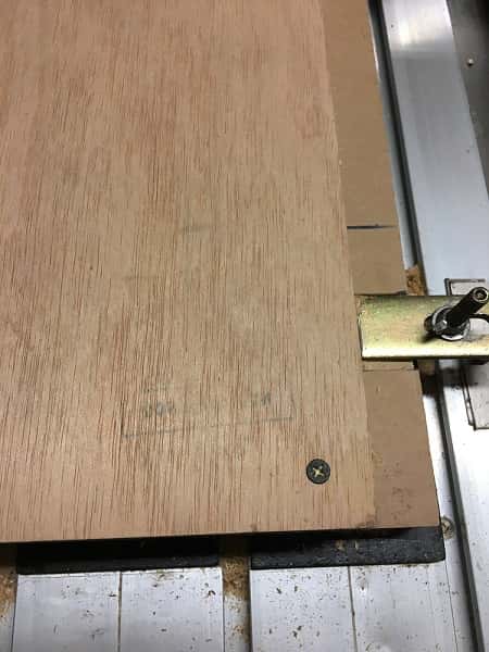
- Keep the same configuration to cut
This is the final result
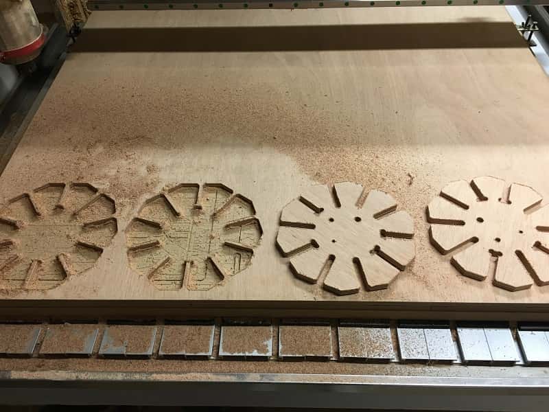

The size that fit the best is 12.2mm


NESTING AND CUTTING
To cut our pieces we tried the deepnest app, but for a reason it wasn't responding, so we decided
to do the nesting manually. Fortunatelly Isma, Camilo and I had designed our objet using the same
width so it saved us some cutting time.

Making the toolpath
For this we used Artcam 2008, which is pretty intuitive and easy to follow. Kept the parameters used for the test since we were using the same material.
Our Lab has a preset tools kit made for this program with the mills and settings specified for our CNC router (CNC Roter 1325).
We used the same parameters that we used for the test, and the same material (12mm plywood), detailed bellow:
- End mill for cutting - 1/8"
- Step over - 0.953mm
- Step down - 3mm
- Feed rate - 50mm/s
- Plunge rate - 50mm/s
Artcam 2018
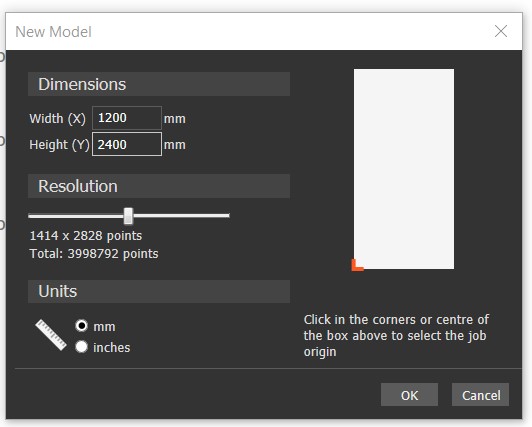
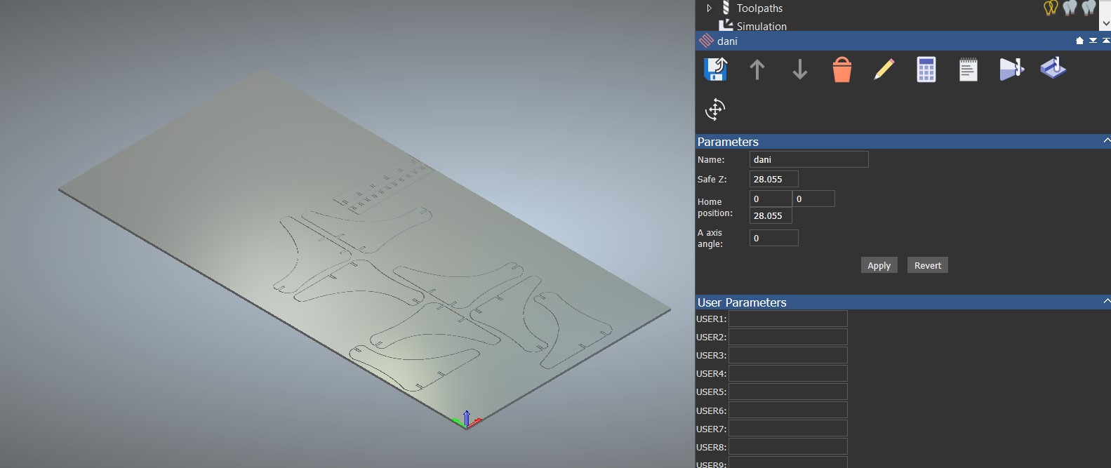
For the previous test we used a lab's computer, but to try it on my own I got the Arcam 2018. It is pretty simmilar to the 2008 version, I leave here the steps to set the parameters.
- Set the size of the material, in this case we used a 1200 x 2400 x 12mm plywood. Here, remember to set the origin (the red cross) on the bottom left corner.
- To upload the .dxf file, go to Vector> Import> select the file
- On the bar located on the right you can select the parameters for this 2D. On the toolpath options:
- Select the tool and set the parameters:
- Set the material
- Add bridges, in this case I had to put the manually because in the automatic mode the bridges are in inaccessible places or too difficult to sand later
- Add a name to the toolpath and "calculate now"
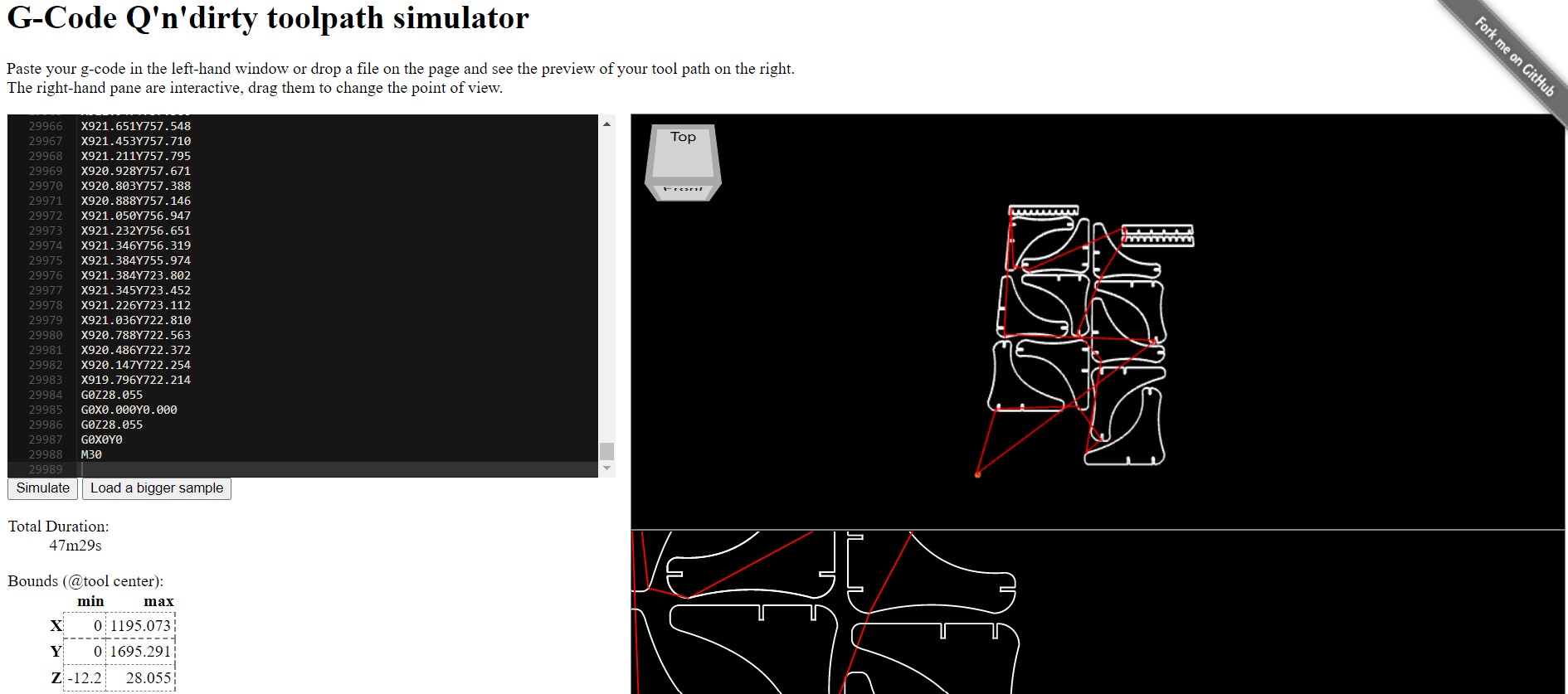
- You can make a simulation of the toolpath to see how it is going to behave
- When you are ok with this steps, save toolpath. Select the folder where you want to have it and machine file format: G-Code(mm)(*tap)>save
- You can also check the code on the online simmulator .
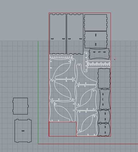
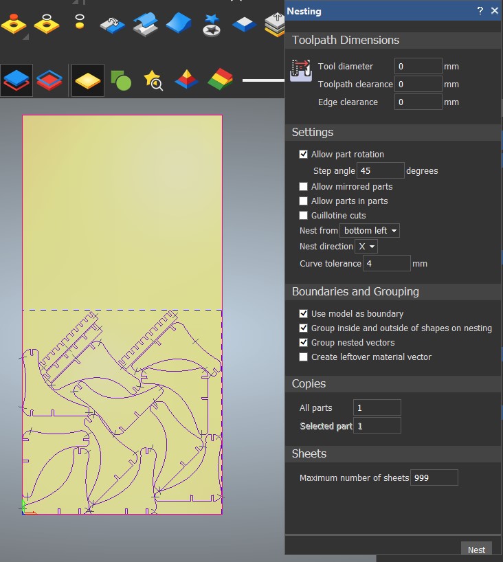
- Artcam has its own nesting tool, you can find it in vector>nest vector. Select the pieces you want to nest, check the allow rotation box, set the curve tolerance, in this case i set 4mm.
This is the result (before and after) I would have saved a lot of material If I had know this tool earlier, I haven't realized how much I can optimize the material just by rotating them.
I'll have this tool on mind for the following projects.

You can find this
tap file and the
ArtCAM file here.
milling
It took about 1 and a half hour to have our pieces ready.
Just to remember the process, once you load the material on the bed you have to secure it with screws, they are already planned in the drill path but
make sure running an air cut test first to make sure that they are not in the design path way, it could cause an accident if it is.
Make sure the dust collector is on and working properly. When everything is set, run the G-Code. And never forget about the safety rules around the machine.

MAKE SOMETHING BIG
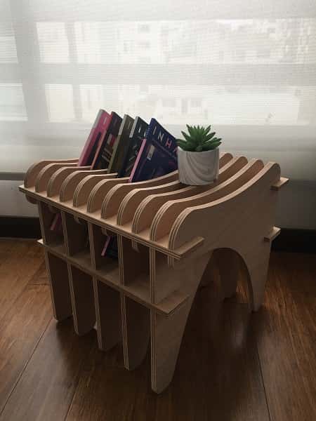
This is my result and assembly process, I really enojoyed doing this activity, it's like a big puzzle.

I used sandpaper to remove the cutting residues. This is normal and may vary depending on the type of wood, the direction of the grain and the condition of the cutter.

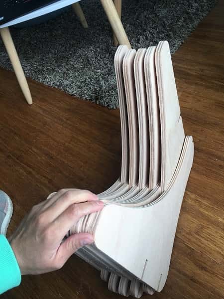
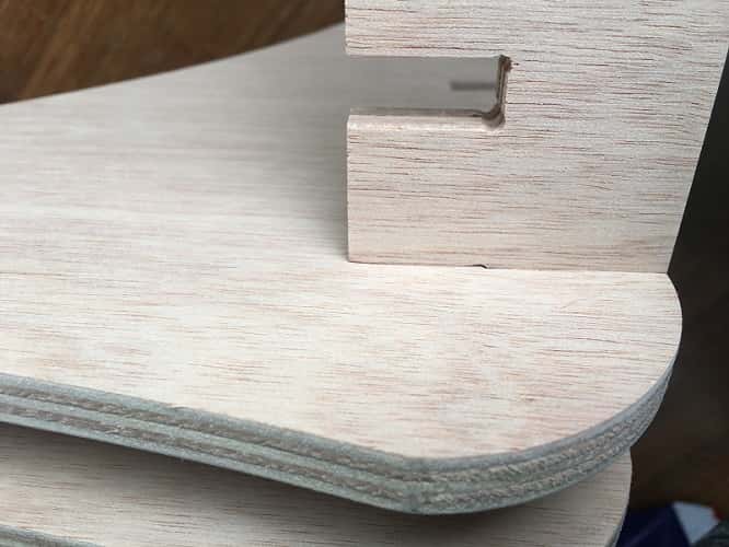
On the design I used dogbones to make sure the pieces fit perfectly together. I really liked
using those details because you can barely see them at the joints. The first pieces were easy to put together but as I added more, it got a little harder.
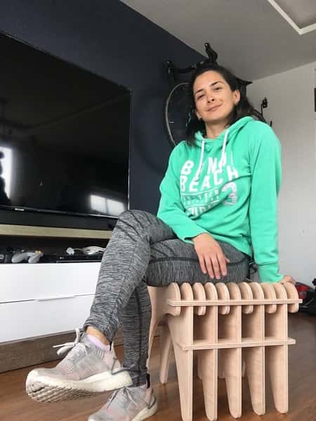
This is the final result, it can be used in different ways, as a seat and as a magazine holder.

SOME THOUGHTS FOR THIS WEEK
While working on my documentation I was listenig to a Netflix documentary called "The creative brain" (I reccomend it)
and picked up some stuff I'd like to share and keep in mind specially for the weeks (like electronics) when I fell I know / understand
nothing. I quote Nathan:
- You learn more and more about less and less, until you know everything about nothing
- Learning new subjects is not easy
- Part of the learning is to be confused, I'm very often frustrated and confussed, because I'm not getting it
- To be creative you have to be willing to be wrong, but also willing to be right, and yet everyone think you're worong
Thinking about this week assignment, I really enjoyed doing it, it is a technology I find really interesting
and I'm exited to keep exploring the possibilities it brings for furniture design.
Looking back, the past few weeks have enriched my creative experience and my discovery of other manufacturing options.
We'll see where this adventure takes me week after week.


