Week 8 Embedded Programming
In the summary below, you can jump directly to topics.
Summary
In this week we will learn what embedded programming is. We find out about various languages and programming environments. Then we put the theory in practice and make our board do something. Depending on your experience, this is limited to blinking an LED or more advanced functions. I’m an absolute beginner at electronics and programming and excited to venture into the unknown! My personal goal is to learn as much as possible about the workflow and process of debugging.
Assignments
Group project:
- Compare the performance and development workflows for different microcontroller families
- Document your work (in a group or individually)
Individual project:
- Read the datasheet for the microcontroller you are programming
- Goal: to know where to find the information you need.
- Program the board you have made to do something, with as many different programming languages and programming environments as possible.
Learning outcomes
- Identify relevant information in a microcontroller datasheet.
- Implement programming protocols.
Have you answered these questions?
- Linked to the group assignment page
- Documented what you learned from reading a microcontroller datasheet.
- Programmed your board
- Described the programming process/es you used
- Included your source code
- Included a short ‘hero video’ of your board
Project management
In preparation of this week’s task, I’m planning the following steps in spiral development:
| Spiral | Tasks | Time |
|---|---|---|
| 1 | Group assignment | 8 hours |
| 2 | Program the board in Arduino IDE | 8 hours |
| 3 | Program the board in other IDE’s and programming languages | 16 hours |
| 4 | Read and document datasheets | 4 hours |
| 5 | Test homelab CNC software | 4 hours |
| 6 | Documentation | 16 hours |
Let’s get started!
This week’s results
This was a week full of learning! We were exposed to many different types of microcontroller families and programming environments. The Blink program was uploaded successfully on an ESP32 that came in the Fab Academy Electronics Kit.
For me, this week was characterized by a lot of failure, debugging and solution-seeking. Because my board was not working, I spent a lot of time trying to fix this. During Input Devices I continued to debug the board and eventually decided to remake it with a regular PCB milling process. In that week, I successfully programmed the LED, button and phototransistor.
Home lab CNC machine building progress
We start with a weekly update of the home lab. Last week, I ordered parts for the CNC. While waiting for them to arrive, I’m going to look into software that came on a USB with the package. It included a nice render of the machine:
The software is only available for Windows. There are other options to talk with the machine. For example, an article from All3DP on Getting the Right Cut with a CNC 3018 Pro provides an overview of other Computer-Aided Manufacturing software to use. Of course mods is possible. And in the regional session, one of the instructors suggested Rhino CAM for a seamless workflow integration with Rhinoceros. Before I start experimenting with other workflows, I’m going to run the software on Windows while using bootcamp. Henk added that the CNC 3018 Pro has plenty of software that runs on other OS than Windows. Examples include Candle, cncjs, Easel and UGS to name a few.
Embedded programming environments and languages
Before we start, let’s find out what our options are for IDE’s and programming languages.
What is an IDE?
An IDE is an Integrated Development Environment. This is a software application used by developers to create new software applications. Usually an IDE consists of at least a text editor, a compiler and extensive documentation. Often, an IDE also has a graphic interface, debugger, version control, and many other plugins.
The goal of this week’s assignment is to program a board with as many environments and programming languages as possible. The following environments are presented on the Embedded Programming 2021 class page:
- Atmel Studio
- Arduino
- Eclipse
- VS Code
- Scratch
- Modkit
- Firefly
For this week’s assignment, I’ve selected three to explore: the Arduino IDE, Scratch and Visual Studio Code.
Arduino IDE. At Waag, we got an introduction to the Arduino IDE. We learned that Arduino is not only a hardware board, but much more! It is also a toolchain, IDE, bootloader, header programming and libraries that can be used by other applications.
Scratch. is an IDE for kids, developed by the Lifelong Kindergarten group at the MIT Media Lab. It is great that an application like this exists, for children to get introduced to programming in a playful way.
Visual Studio Code is an IDE developed by Microsoft. In the last couple of weeks, I’ve used this as a text editor for this Fab Academy website. I’m writing markdown files, however, apparently it can also be used as an IDE!
What programming languages are available?
Embedded programming can be done in many different languages. The following languages are presented on the Embedded Programming 2021 class page:
- assembly languages: hex file, instruction set, opcodes, mnemonics, directives, expressions, avr-as, inline
- C
- C++
- Arduino
For guidance, I consulted the practical guide to (embedded) programming by Brian Plancher. It is important to note that in most languages, you can and will call upon libraries. For example, the avr-libc mentioned in the guide. This results in shorter and more efficient code. The downside is that it can slow down loading time of the code.
C Because C is a foundational language upon which most programming languages are based on, I’ll start with C.
C++ What are the similarities and differences between C and C++?
Arduino
The Arduino programming language is user-friendly and can be divided in three main parts: functions, values (variables and constants), and structure. When you write a program (for example in the Arduino IDE), you can save it as an .ino file. Arduino development software turns your code into a C++ program.
A sketch is the name that Arduino uses for a program. It’s the unit of code that is uploaded to and run on an Arduino board. A standard block of Arduino code in a sketch consists of three elements:
- Information about the developers
- Setup (void setup) - this is the pin you have to use
- Loop - function that runs over and over
Arduino simulators on TinkerCad allow you to simulate a configuration without building a physical board configuration.
Group assignment: Microcontrollers families
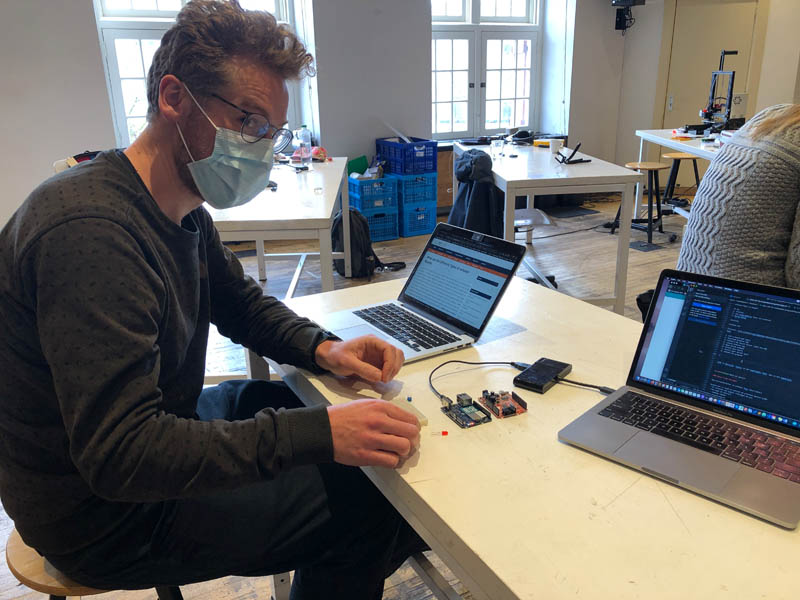
In the sections that follow, we experiment with the embedded programming workflow of a variety of boards available at Waag in Amsterdam. This week, I did the group assignment together with Loes, Nadieh and Douwe.
All microcontroller families listed on the Fab Academy schedule are:
- LOGIC
- Megaprocessor
- 8051
- PIC
- MSP
- AVR • 6-100 pin packages ATtiny45V, ATtiny44A • prior ATtiny412, ATtiny1614, ATtiny3216 • 1-series • 8 bit, 1.8-5.5V, 20 MHz • single-cycle global instructions • simple peripheral register access • low pin-count packages • one-pin serial programming ATtiny1624 • 2-series • programmable gain amplifier AVR128DB32 • 24 MHz • analog signal conditioning • level shifting • hardware multiplier DD • coming
- ARM - [SAMD] D11C, D11D, D21E, D51 • 32 bit, 1.6-3.6V • faster clocks, more complex clock distribution and synchronization • more powerful peripherals, more complex register access and libraries • diverse family, larger packages • standard in-circuit debugging
- Xtensa [ESP] ESP8266, ESP32 • integrated RF, networking
- RISC-V • open architecture
- PSoC, xCORE, Propeller, Lattice, NVIDIA • parallel
At the Waag FabLab in Amsterdam, we have the following microcontroller families available for comparison:
- Arduino Uno
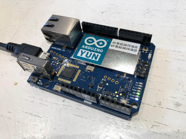
- Arduino Yun
- Arduino Mega - more pins
- Arduino Mini
- Fabschoolino education board
- Makey Makey
- ESP 8266 board - integrated wifi and bluetooth
- ESP 32 - with camera / webserver video-stream
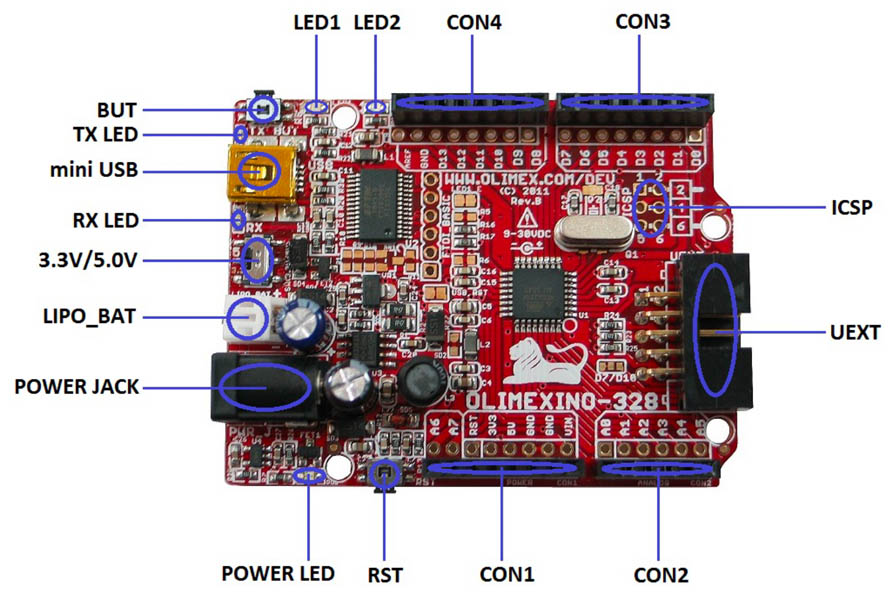
- Olimex-328 - (arduino with couple of plusses)
Finding out the workflow of programming boards is the most important goal of this week. A comparison between different types of Arduino boards can be found in this article.
Arduino Yun + Blink
In the Arduino interface, click Help and Getting Started. This will open a local html page with a tutorial from Arduino.
-
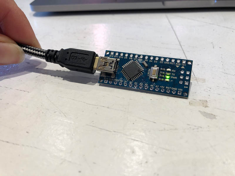
Get an Arduino board and USB cable. You need a standard USB cable (A plug to B plug): the kind you would connect to a USB printer, for example. For the Arduino Nano, you’ll need an A to Mini-B cable instead.
-
Download the Arduino IDE
-
Connect the board (Green light for ON)
-
Launch Arduino app
-
Open Blink example
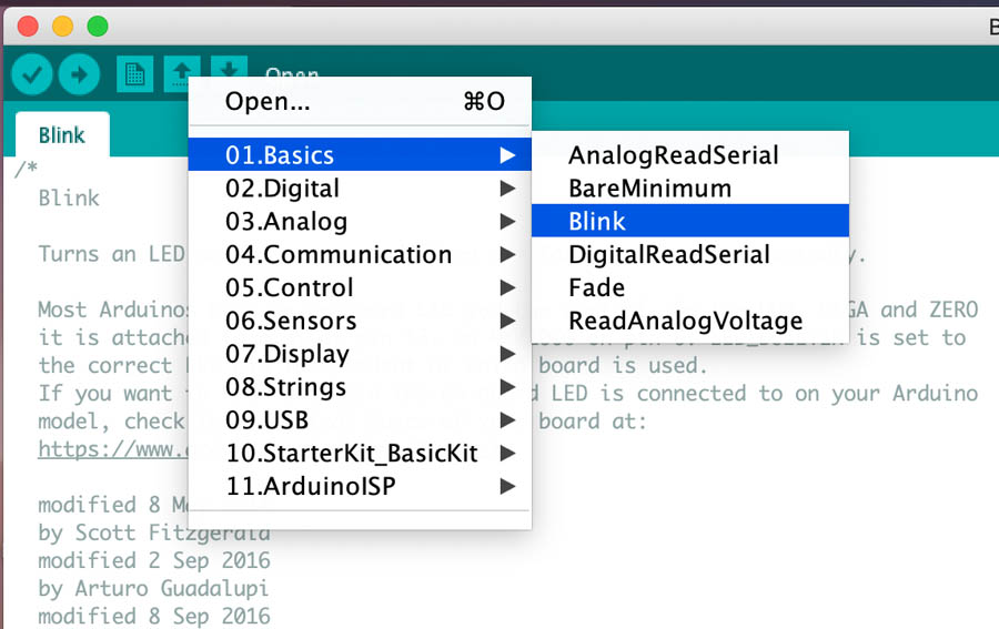
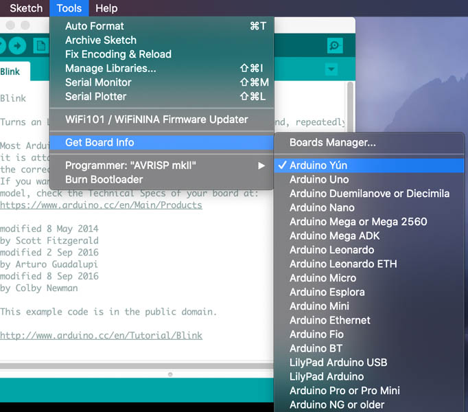
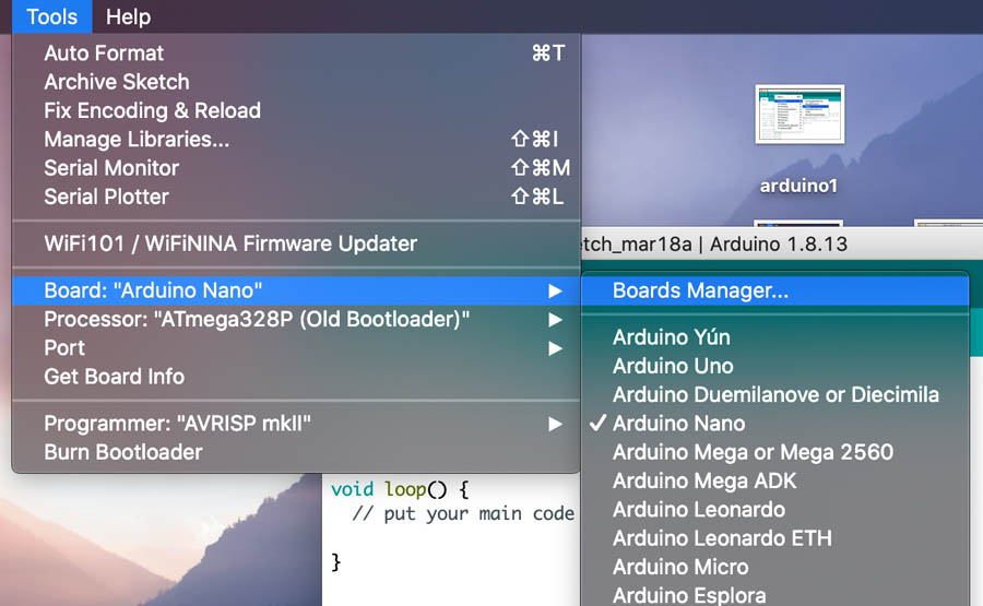
Select your board via Tools and Get Board Info.
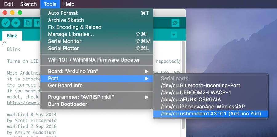
Select your serial port. Select the serial device of the Arduino board from the Tools > Serial Port menu. On the Mac, this should be something with /dev/tty.usbmodem (for the Uno or Mega 2560) or /dev/tty.usbserial (for older boards) in it.
Upload the program by clicking the upload button in the environment.

Done!
Now we’re changing the code and upload it again. I named it Blink 2, and changed the delay to 2000 instead of 1000.
Check!
Arduino Yun + breadboard + fade
The next step is to blink an LED on an external LED. To make and test a circuit, you can use a breadboard as a prototyping tool. For starters, a really good explanation on the workflow with a breadboard is this Arduino tutorial on breadboards and LEDs by LadyAda.net.
This is the Arduino code for blinking an LED:
// the setup function runs once when you press reset or power the board
void setup() {
  // initialize digital pin LED_BUILTIN as an output.
  pinMode(LED_BUILTIN, OUTPUT);
}

// the loop function runs over and over again forever
void loop() {
  digitalWrite(LED_BUILTIN, HIGH);   // turn the LED on (HIGH is the voltage level)
  delay(1000);                       // wait for a second
  digitalWrite(LED_BUILTIN, LOW);    // turn the LED off by making the voltage LOW
  delay(1000);                       // wait for a second
}
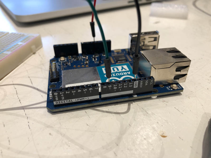
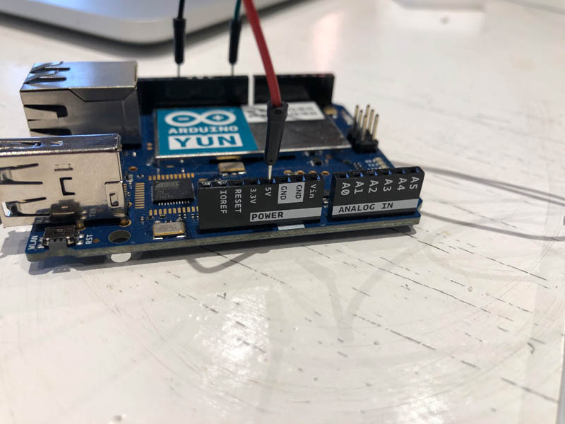
This is the pin configuration on both sides of the Arduino.
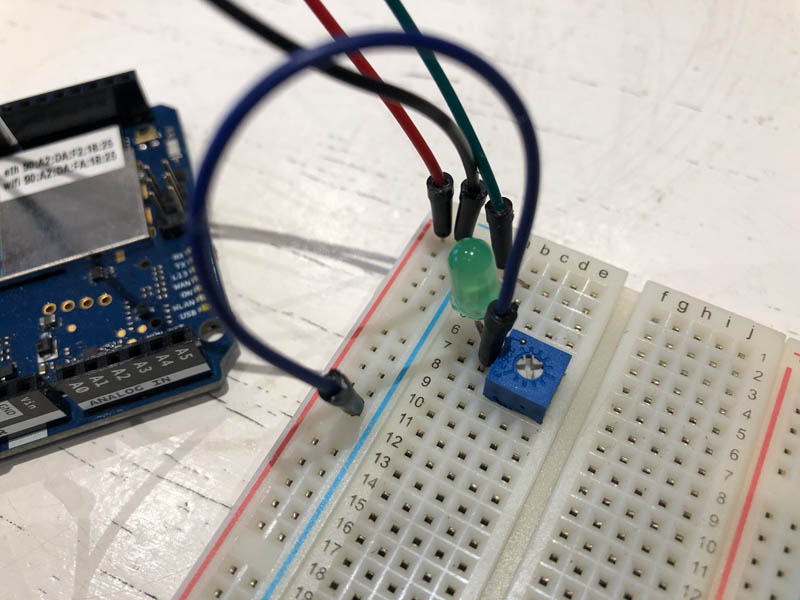
Close-up of the breadboard.
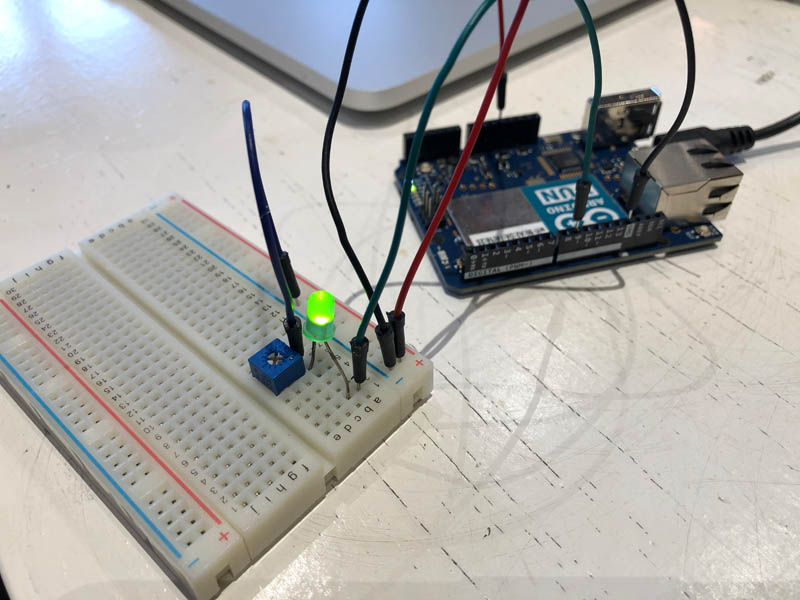
And the working LED!
Now we’re going to upload the Arduino Fading code:
int ledPin = 9;    // LED connected to digital pin 9

void setup() {
  // nothing happens in setup
}

void loop() {
  // fade in from min to max in increments of 5 points:
  for (int fadeValue = 0 ; fadeValue <= 255; fadeValue += 5) {
    // sets the value (range from 0 to 255):
    analogWrite(ledPin, fadeValue);
    // wait for 30 milliseconds to see the dimming effect
    delay(30);
  }

  // fade out from max to min in increments of 5 points:
  for (int fadeValue = 255 ; fadeValue >= 0; fadeValue -= 5) {
    // sets the value (range from 0 to 255):
    analogWrite(ledPin, fadeValue);
    // wait for 30 milliseconds to see the dimming effect
    delay(30);
  }
}
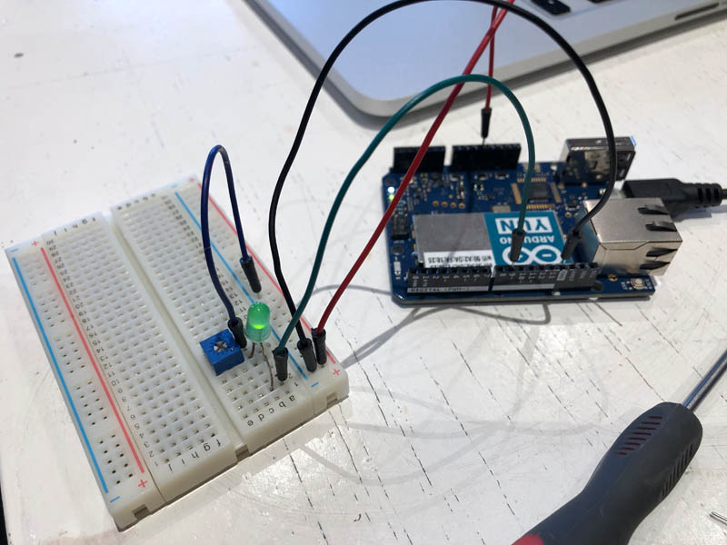
Fade works!
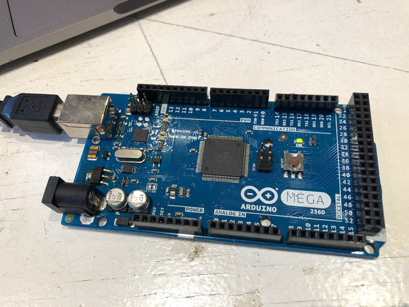
Arduino Mega + Blink
Arduino Mega is bigger than the other boards.
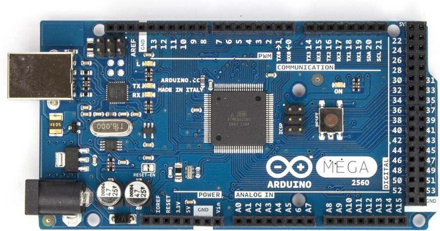
You use the same workflow as the Yun board, but then with the Arduino Mega board selected in Tools and Get Board Info. After uploading the Blink program, a tiny yellow LED lights up in the upper left corner.

Olimexino-328 + blink
The Olimex is “an Arduino-like development board” according to their user manual, page 10:
Cable: usb micro - USB to usb B port
After you have downloaded and installed (or extracted) the environment you should connect the OLIMEXINO-328 to the computer via an USB type A to USB mini cable.
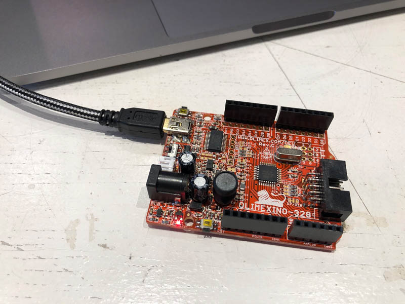
In Tools -> Board you should select Arduino Duemilanove w/ ATmega328. This is the correct setting for the Olimex. Surprisingly, it is not needed to install drivers!
The first time you connect the board you would be asked for drivers. You can find the drivers needed for OLIMEXINO-328 in the install folders of the Arduino IDE (usually in folder “drivers”).
After uploading, the blink program works! The LED is visible in the left upper corner.
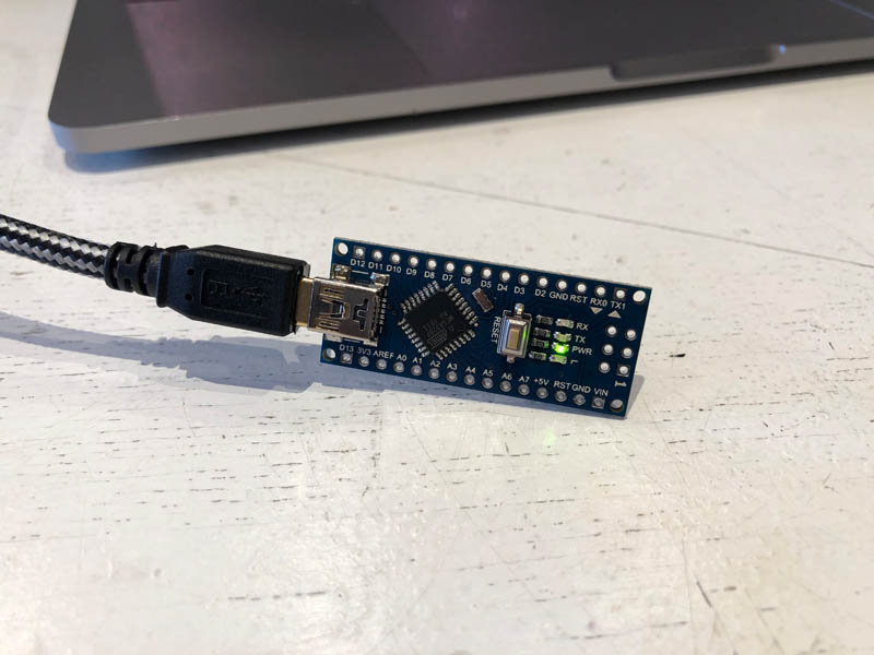
Arduino Nano + blink
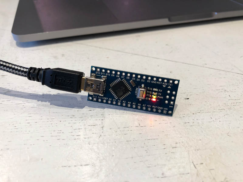
The next board is the Arduino Nano. I connected this to the laptop, and it shows power.
After uploading the blink program, the following error showed up:
Error: avrdude: stk500_recv(): programmer is not responding
According to this article on the Arduino support page, in case you are getting this error it is due to one of the reasons below. You will have to try the following suggestions:
- Make sure you have selected the correct board and port for your Arduino board from the Tools > Port menu.
- Remove any connections to pins 0 and 1. These pins are used for communication with your computer, including uploads. Connecting anything to these pins can interfere with uploads.
- Do a loopback test. If it passes, you know the USB to TTL serial adapter chip on your Arduino board is good. If it fails, your board is damaged beyond economical repair and should be replaced.
- If the loopback test passes. Try burning the bootloader again:
- Using a programmer (example using a MKR board)
- Using another Arduino board, for example an Arduino Mega or an Arduino UNO
Mistake 1: I selected the Arduino Mini instead of Nano. According to Arduino, this board is retired.
I retried uploading the code, and it still gave the same error. That’s why I looked into the third recommendation.
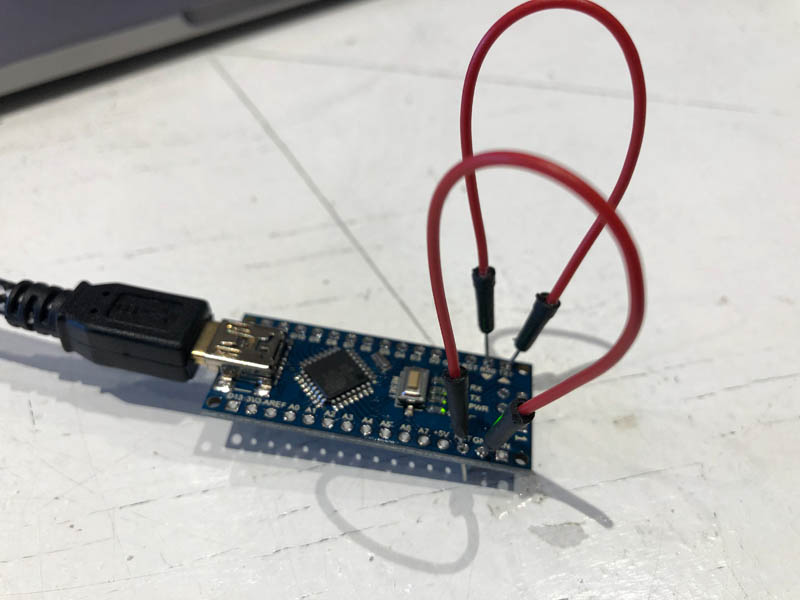
How to do a loopback test
The loopback test is a troubleshooting procedure to test the serial communication between an Arduino board and your PC. A failed loopback test indicates a problem with one or more of the following:
- The host computer
- Hardware driver
- USB cable
- The board’s USB to Serial converter
According to Arduino support you can do this with jumper cables. I tried to do this, but it didn’t give any results.
Then I played around with the settings and tried to select the old bootloader. This solved the problem!
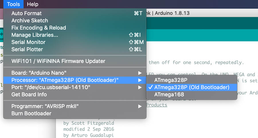
After changing this setting, the LED blinked.
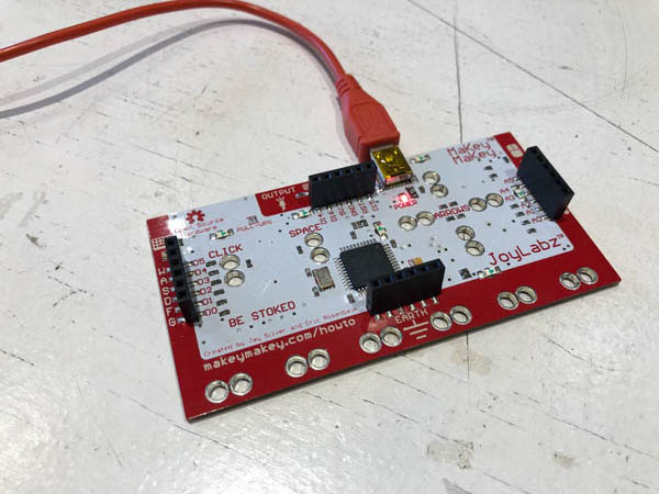
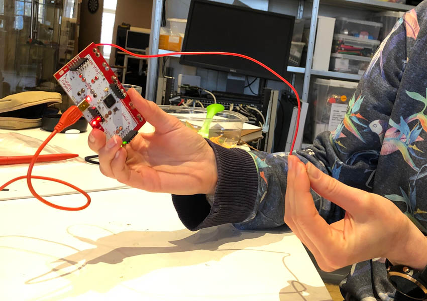
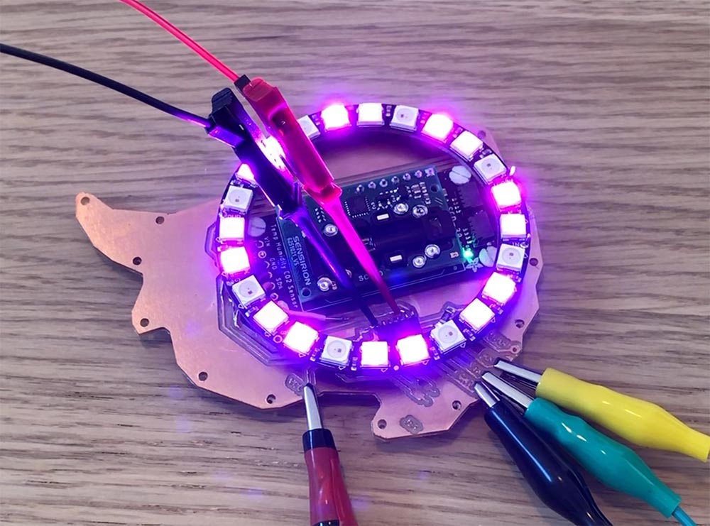
Makey Makey
The Makey Makey is a fun board for children.
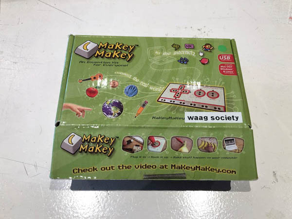
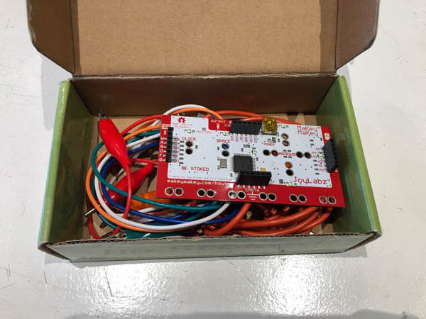
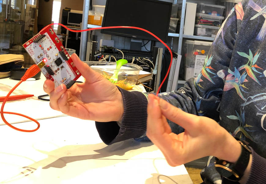
With the basic guide on how to set up the Makey Makey for the first time I experimented with this board. You start with powering the board, and with attaching the alligator clip to ground.
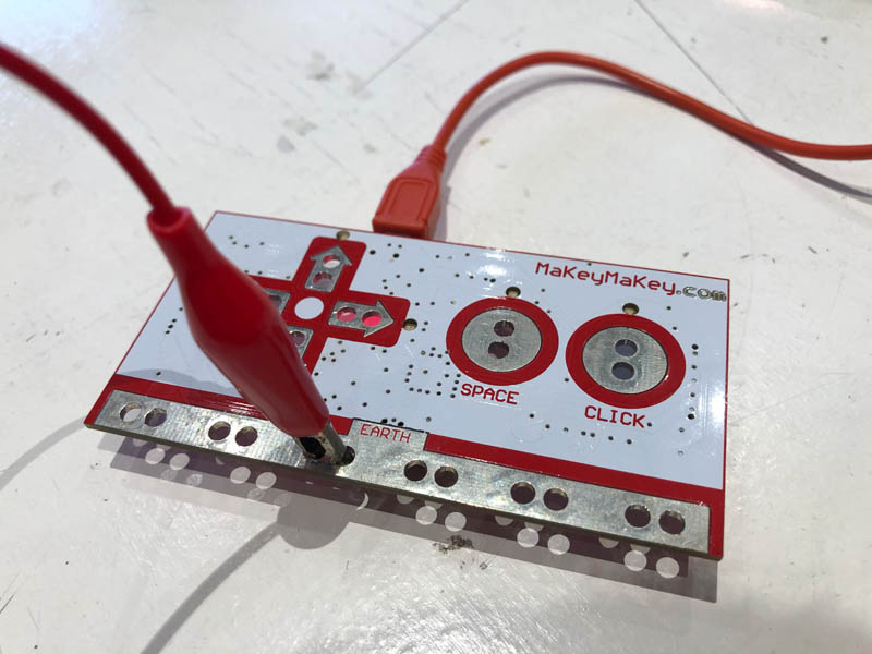
You can close the circuit by touching the sensor on the back. Your body functions as a resistor.
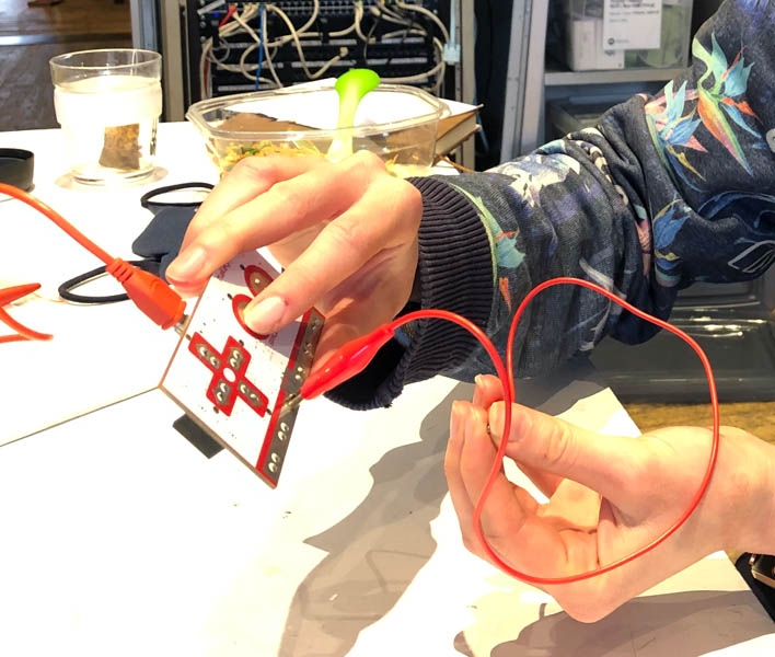
And it blinks!
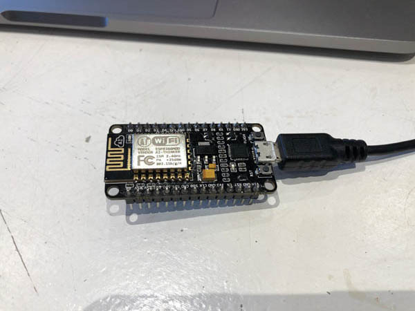
ESP8266MOD AI-thinker
The last board is an ESP8266MOD by NodeMCU. This is an open-source firmware and development kit that helps you to prototype your IOT product within a few Lua script lines.
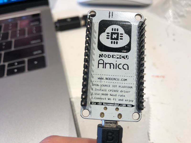
The workflow is as follows:
- Install CP2102 driver
- Use 9600 baud rate
- Connect Wifi and enjoy
I didn’t have time to complete the workflow of this board during the session at Waag. However I will try this later!
Read a datasheet
For this assignment I’ve read two datasheets: the one about the ATtiny412 that’s on my own board and the one for the ESP32-WROOM32 that came in the Fab Academy Electronics Kit. Link to info about what serial communication is.
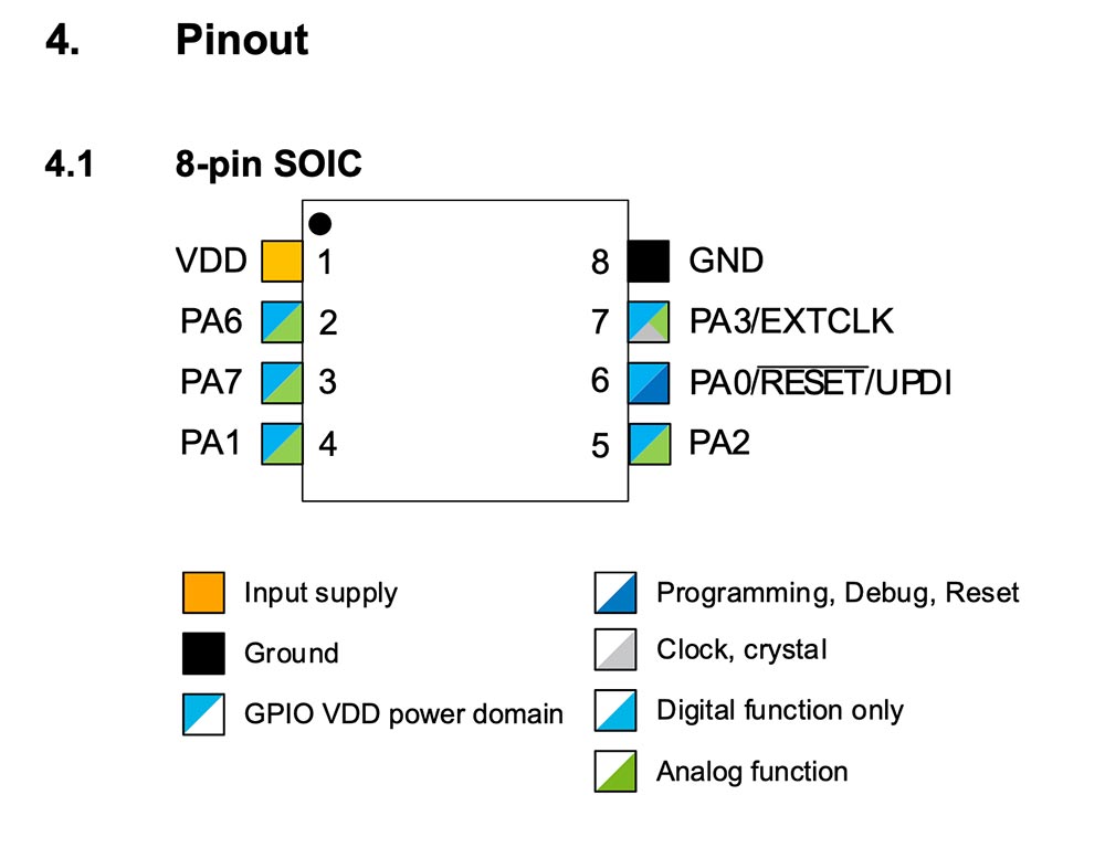
ATtiny412
The ATtiny412 datasheet can be found on the server of CBA. A newer version from Microchip is available.
What is it? The ATtiny212/412 are members of the tinyAVR® 1-series of microcontrollers, using the AVR® processor with hardware multiplier, running at up to 20 MHz, with 2/4 KB Flash, 128/256 bytes of SRAM, and 64/128bytes of EEPROM in an 8-pin package. The tinyAVR® 1-series uses the latest technologies with a flexible, low-power architecture including Event System and SleepWalking, accurate analog features, andCore Independent Peripherals.
Pinout On page 13 of the datasheet is the pinout of the ATtiny412:
ESP32-WROOM32
The ESP32-WROOM32 datasheet is a 27-pages long document that can be found here. On page 6, it notes: “for details on the part numbers of the ESP32 family of chips, please refer to the document ESP32 Datasheet”. This is a document of 65 pages.
What is it? ESP32 is a single 2.4 GHz Wi-Fi-and-Bluetooth combo chip designed with the TSMC ultra-low-power 40 nm technology (page 8, ESP32 datasheet). ESP32-WROOM-32 is a powerful, generic Wi-Fi+BT+BLE MCU module that targets a wide variety of applications, ranging from low-power sensor networks to the most demanding tasks, such as voice encoding, music streaming and MP3 decoding (page 6, ESP32-WROOM32 datasheet).
What can you do with it? Page 11 of the ESP32 datasheet provides a non-exhaustive list of potential applications. These include:
- Generic Low-power IoT Sensor Hub or Data Loggers
- Cameras for video streaming
- Internet music players, live streaming devices, internet radio players, audio headsets
- Over-the-top (OTT) Devices
- Speech Recognition
- Image Recognition
- Energy monitoring
- Industrial and Home Automation
- Smart Building: plugs, door locks, lighting
- Smart Agriculture: greenhouses, irrigation
- Robots: agriculture, industrial robotics
- Baby monitors
- Toys: remote control toys, proximity sensing toys, educational toys
- Wearable Electronics: Smart watches and bracelets
That’s an impressive list!
Functionality? The board has integrated Bluetooth®, Bluetooth LE and Wi-Fi to ensure that a wide range of applications can be targeted.
Page 32 of the second document provides an overview of ‘Peripherals and Sensors’. I’m noting down the functions that might be useful for Fab Academy and future projects.
- General Purpose Input / Output Interface (GPIO). ESP32 has 34 GPIO pins which can be assigned various functions by programming the appropriate registers. There are several kinds of GPIOs: digital-only, analog-enabled, capacitive-touch-enabled, etc. Analog-enabled GPIOs and Capacitive-touch-enabled GPIOs can be configured as digital GPIOs.
- AnalogtoDigital Converter (ADC) can be used to convert two digital signals into two analog voltage signal outputs.
- Touch sensor: ESP32 has 10 capacitive-sensing GPIOs, which detect variations induced by touching or approaching the GPIOs with a finger or other objects.
- Hall Sensor: ESP32 integrates a Hall sensor based on an N-carrier resistor. When the chip is in the magnetic field, the Hall sensor develops a small voltage laterally on the resistor, which can be directly measured by the ADC.
- Infrared Remote Controller: The infrared remote controller supports eight channels of infrared remote transmission and receiving. By programming the pulse waveform, it supports various infrared protocols.
Pin layout, pin definitions, and power scheme
ESP-32-WROOM-32 pin layout image by Circuits4You.
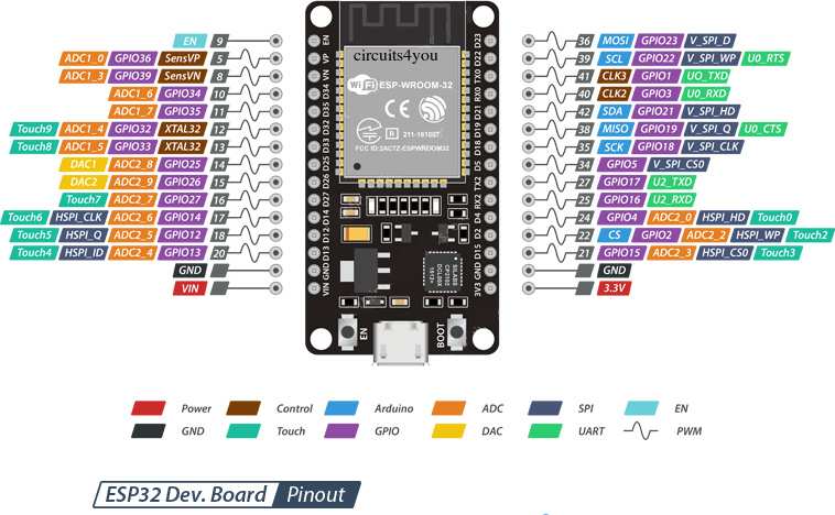
ESP32-WROOM-32 has 38 pins. Page 37 contains a table with the Peripheral Pin Configurations. The pin dot marking is shown in chapter 6, Package Information, on page 49. This information is needed for soldering the board in the right direction.
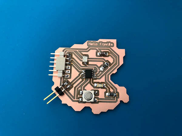
Program your board
My board has an ATtiny412 microprocessor. Arduino IDE doesn’t have the megaTinyCore libraries pre-installed. They are provided here, by SpenceKonde on GitHub.
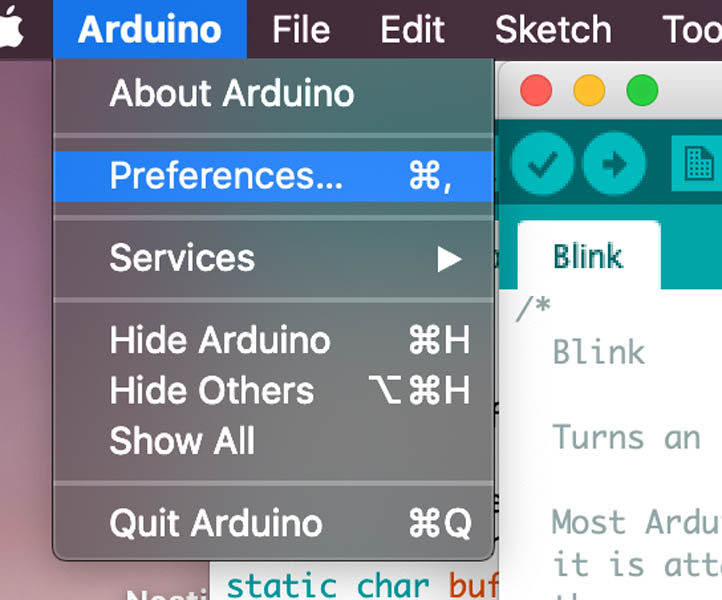
Open the Arduino IDE, click Arduino -> Preferences.
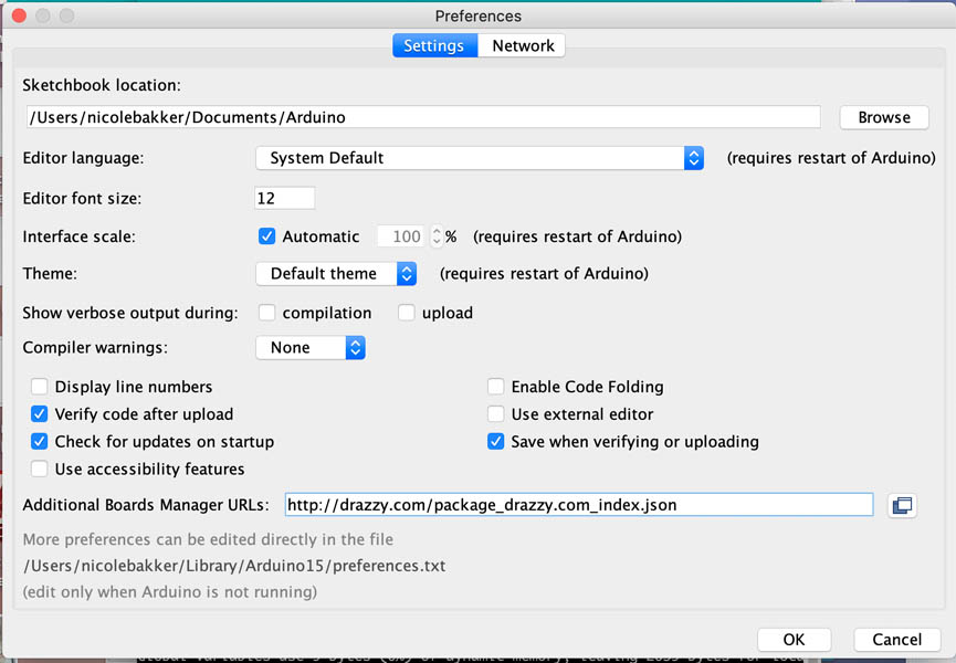
Add the http://drazzy.com/package_drazzy.com_index.json link to the Additional Boards Manager URLs:.
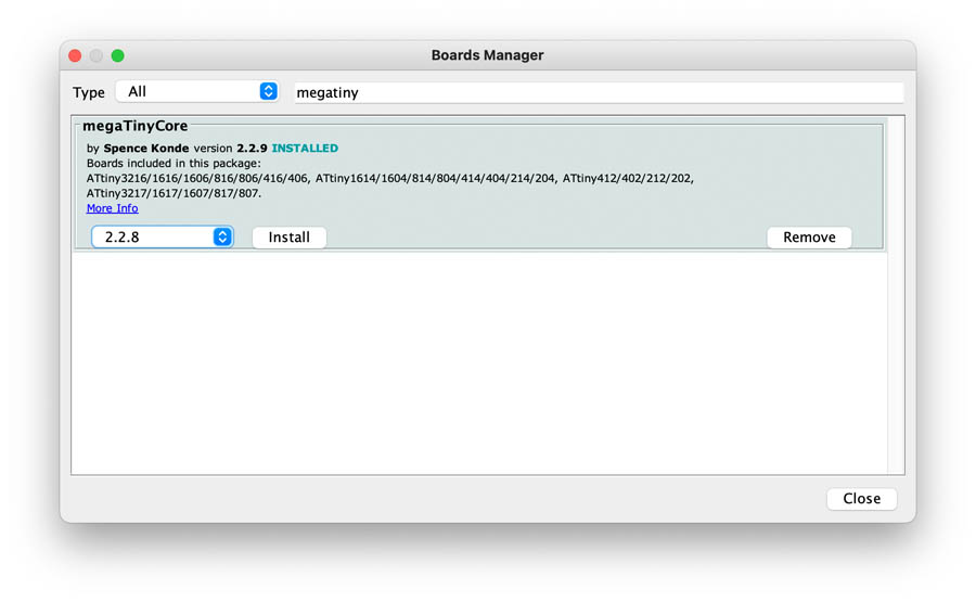
Navigate to Tools -> Boards -> Boards Manager... to add megaTinyCore.
Type megaTinyCore and click Install. For best results, choose the most recent version.
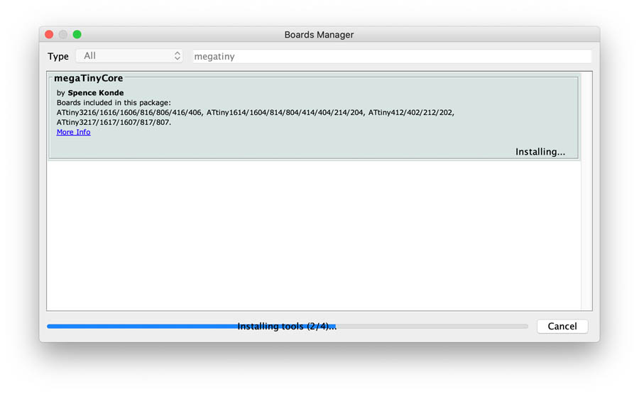
After installation you can close the window and search for the ATtiny412 board.
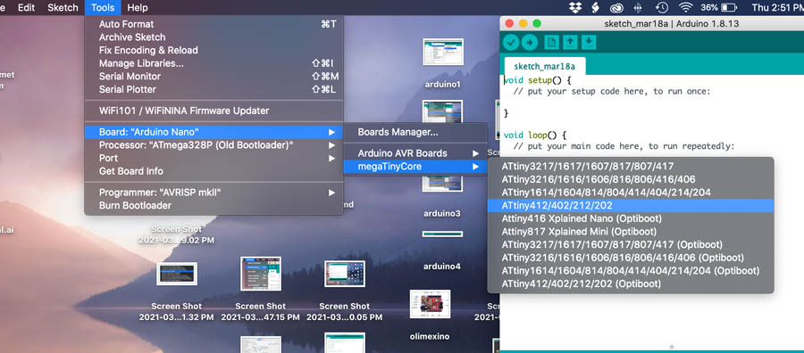
Now you’re ready for programming the ATtiny412.
Henk: For programming the t412: first try the hello echo ino from Neil’s classes. And to get the right ports to use tx and rx use this guide on pin swapping by SpenceKonde available on GitHub.
“On all parts, the UART pins can be swapped to an alternate location. This is configured using the Serial.swap() or Serial.pins() methods. Both of them achieve the same thing, but differ in how you specify the set of pins to use. This must be called before calling Serial.begin().
Serial.swap(1) or Serial.swap(0) will set the the mapping to the alternate (1) or default (0) pins. It will return true if this is a valid option, and false if it is not (you don’t need to check this, but it may be useful during development). If an invalid option is specified, it will be set to the default one.
Serial.pins(TX pin, RX pin) - this will set the mapping to whichever mapping has the specified pins as TX and RX. If this is not a valid mapping option, it will return false and set the mapping to the default. This uses more flash than Serial.swap(); that method is preferred.
Bootloaders are available for both UART mappings; the UART bootloader option selected when you do “burn bootloader” for an Optiboot board definition is the serial port that the uploaded bootloaded will use.”
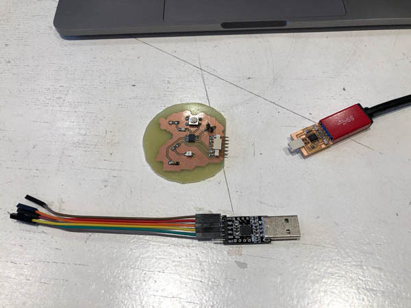
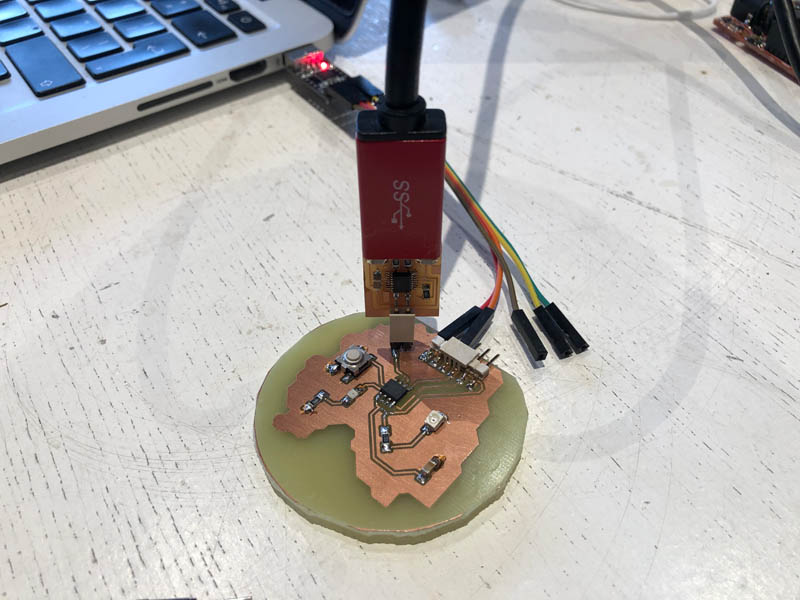
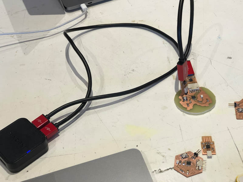
Next, attach the UPDI and FTDI to the board. Make sure to connect the ground pin to the right side. As a reminder:
- 6-pins = ftdi
- 2-pins = updi
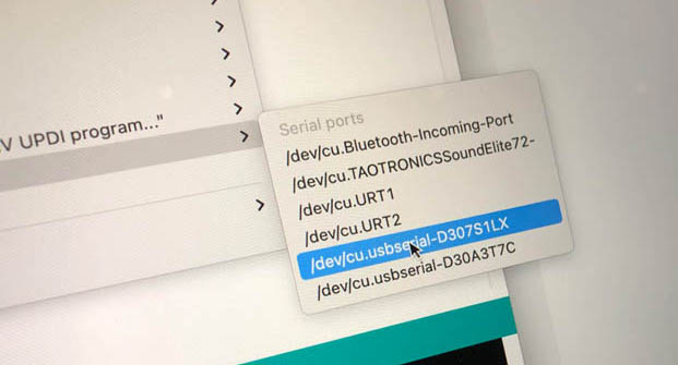
Make sure to select the correct Port.
I opened the blink program and the hello echo sketch. In both cases, the program didn’t arrive at the microprocessor.
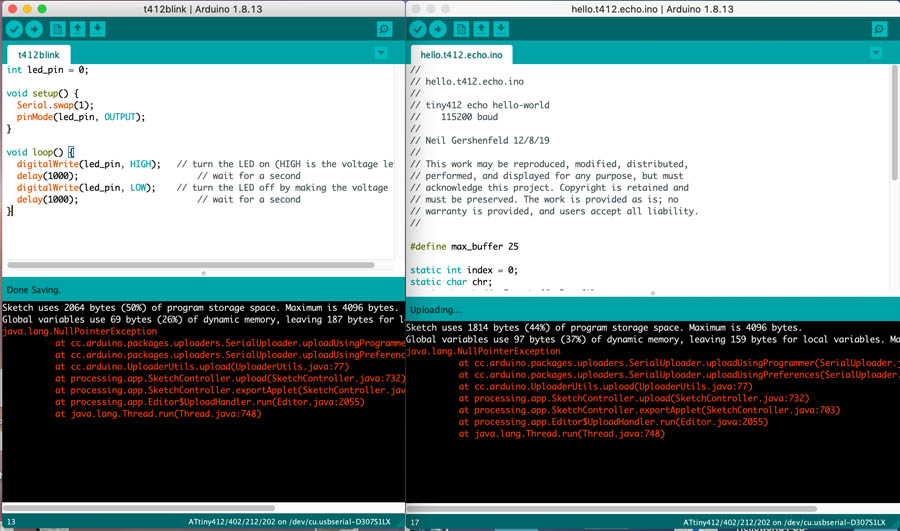
Error message: `java.lang.NullPointerException`

Sketch uses 1814 bytes (44%) of program storage space. Maximum is 4096 bytes.
Global variables use 97 bytes (37%) of dynamic memory, leaving 159 bytes for local variables. Maximum is 256 bytes.
java.lang.NullPointerException
	at cc.arduino.packages.uploaders.SerialUploader.uploadUsingProgrammer(SerialUploader.java:295)
	at cc.arduino.packages.uploaders.SerialUploader.uploadUsingPreferences(SerialUploader.java:90)
	at cc.arduino.UploaderUtils.upload(UploaderUtils.java:77)
	at processing.app.SketchController.upload(SketchController.java:732)
	at processing.app.SketchController.exportApplet(SketchController.java:703)
	at processing.app.Editor$UploadHandler.run(Editor.java:2055)
	at java.lang.Thread.run(Thread.java:748)
StackOverflow explanation of nullpointerexception.
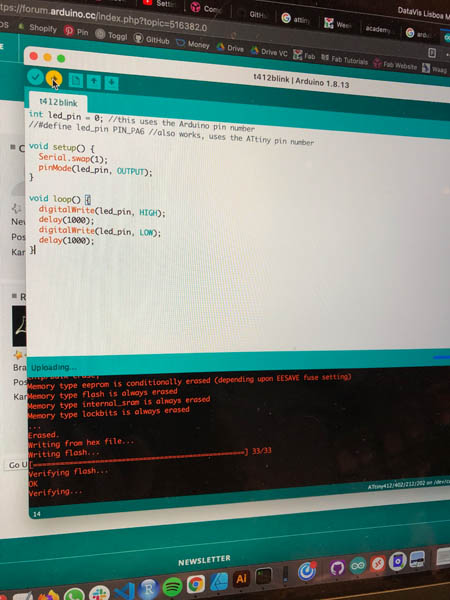
I decided to uninstall version 2.2.9 and install older versions of the megaTinyCore library. This didn’t solve the problem.
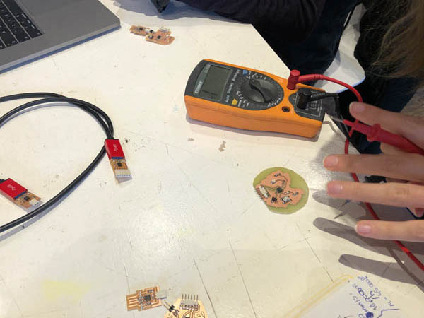
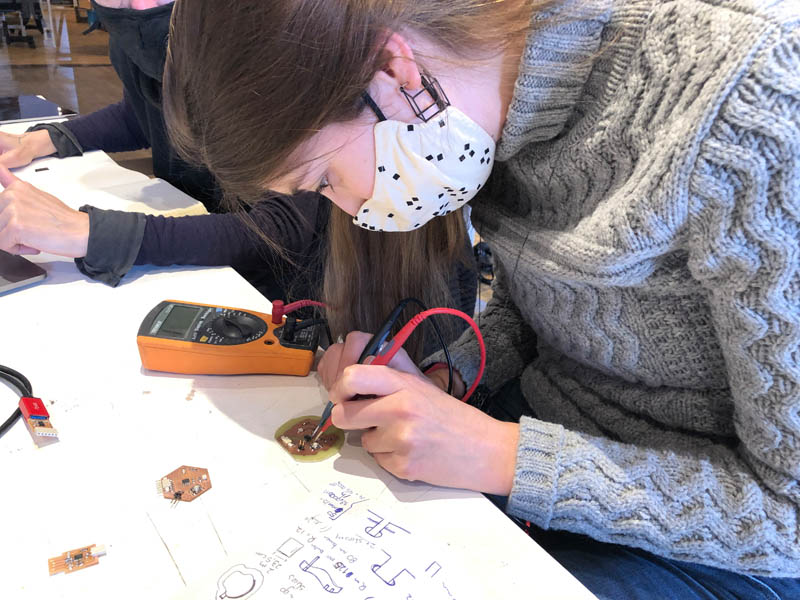
We connected my board on Nadieh’s computer to find out what the problem is.
And it make a connection, but gave a different error. So there must be an issue with my connection. Other Mac-users in our group had the same problem. We tried to install different Arduino and megaTinyCore library versions, but that didn’t solve it.
Nadieh used a multimeter to check the traces.
Wrong direction of LED?
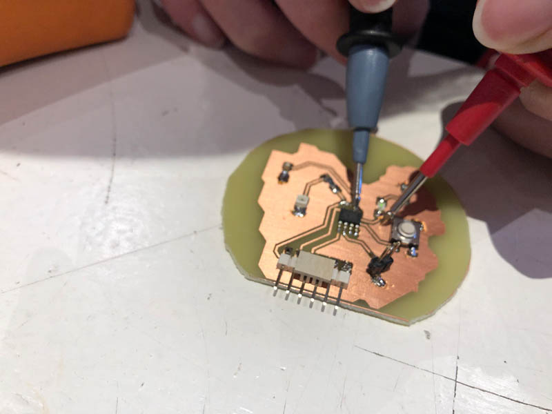
Soldered it the wrong way. Green to the resistor side.
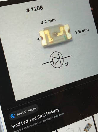 http://smdleddokoeri.blogspot.com/2017/02/led-smd-polarity.html
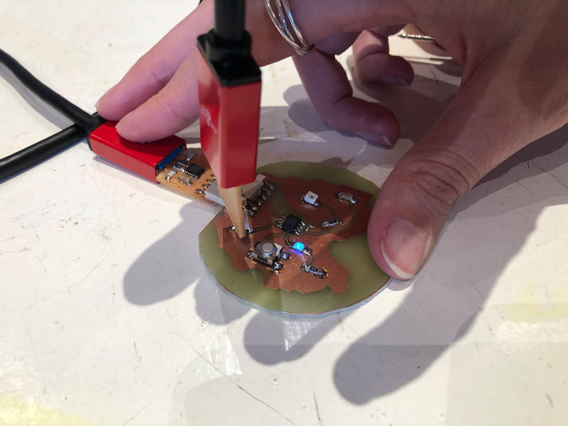
Next, I desoldered the green LED and replaced this with a blue LED.
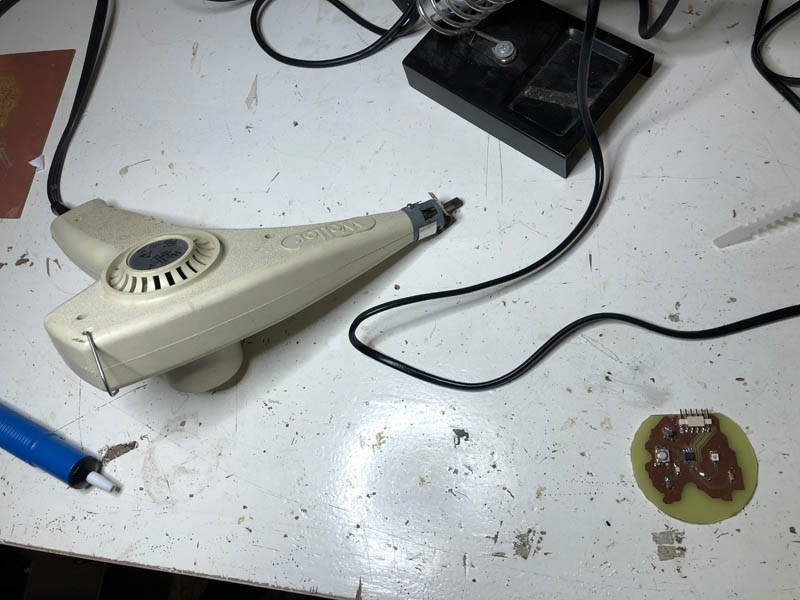
Now the LED lights up, but my board still doesn’t make a connection with the UPDI.
Possible causes are:
- UPDI broke off during programming, I resoldered this. Perhaps it’s a hardware issue.
- Microcontroller might not work.
Debugging
The recitation on debugging provides advice on how to do this.
Debugging, potential causes:
- Megatinycore install: perhaps an older version?
- Select Optiboot board, this resulted in a different error message: avrdude:
- Version 1.1.5.
Tutorial from Fablab Aalto: Setting up UPDI Programming Toolkit with Arduino, megaTinyCore and pyupdi. From video Kris: 5 volt ftdi cable needed.
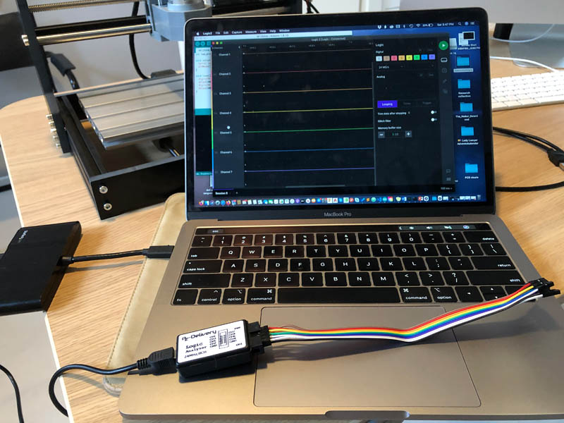
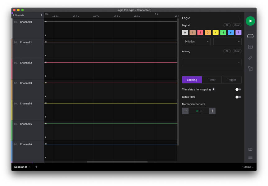
Logic Analyzer
A logic analyzer is a debugging tool used to record and view digital signals. It checks if the bits arrive. The device in the Fab Academy Electronics Kit is from AZ delivery. The datasheet can be found here.
These devices are great for debugging embedded applications. In the mostcommon case, a developer working on firmware for a microcontroller will write acode to communicate with another component, possibly using protocols likeOne-Wire, UART (USART), I2C (TWI) or SPI. To verify the functionality or todiagnose errors in the firmware, a logic analyzer is connected to the digital I/Opins used for communication and records the activity during testing. Therecording is then show on the PC so the user can view the actual behavior ofthe firmware, and compare that with the expected behavior to narrow down andidentify the source of the issue, or to verify that the operation is correct.
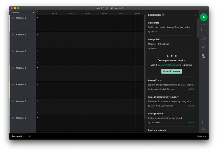
Software: Saleae Logic 2 app and/or Pulseview.
- User guide & videos: https://support.saleae.com/user-guide
- Logic analyzer tuturial: https://www.youtube.com/watch?v=u1DYs2I-_lU
Software interface:
Due to time constraints I wasn’t able to test my board with the logic analyzer yet. I have never worked with this diagnostic tool before, and because there are so many new things this week I decided to move on with a back-up solution of a working board, the ESP32. This brings back the focus of this week on embedded programming. Later, during Input Devices I continued to debug the board and eventually decided to remake it with a regular PCB milling process. In this week, I also programmed the LED, button and phototransistor.
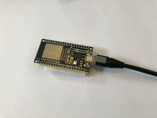
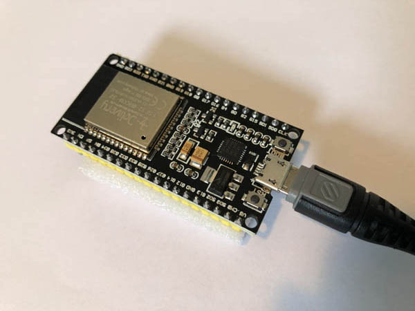
Back-up solution: program the ESP32
I started with following this tutorial provided by Henk: a guide on how to install an ESP32 board in the Arduino IDE. Arduino also provides a guide on how to install additional libraries.
Next, you need to download the contents of the esp32-arduino GitHub repository. You can visit GitHub and download it manually or simply click below download button.
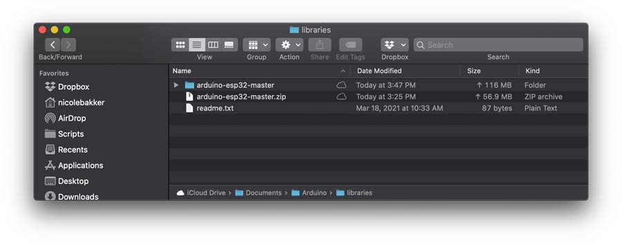
First, I downloaded the file and opened this in the Arduino Board Manager. After running a test program, it gave the following issue:
Error message: Invalid library found in C:[path].
And indeed, the folder is empty. Something went wrong with installing this library. I also checked the get.exe file and it gave this error.
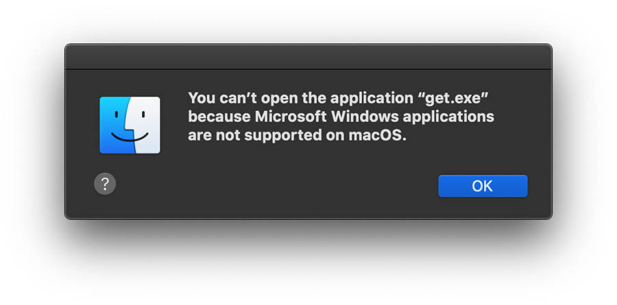
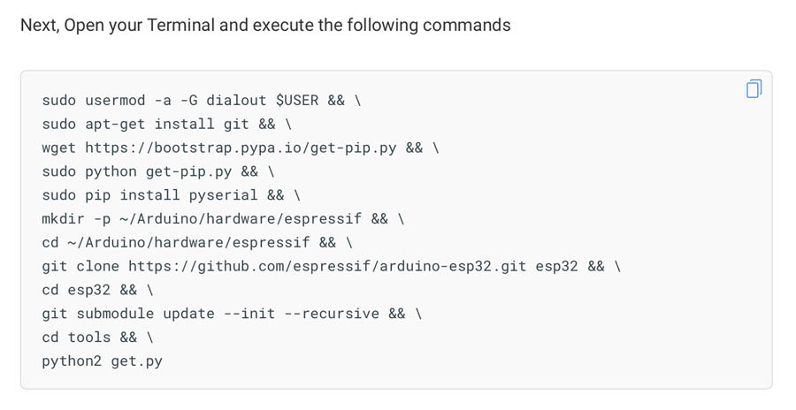
Next, I tried executing the following commands in Terminal. This failed because there is a compatibility issue with python and pip on my Mac.
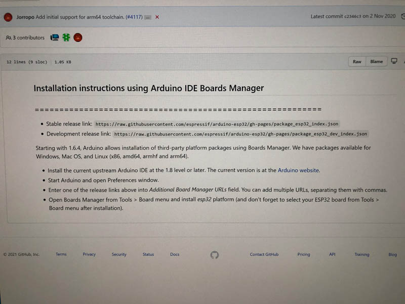
To solve this, I went directly to the GitHub page for Installation instructions using Arduino IDE Boards Manager. These are the recommended steps:
- Install the current upstream Arduino IDE at the 1.8 level or later. The current version is at the Arduino website.
- Start Arduino and open Preferences window.
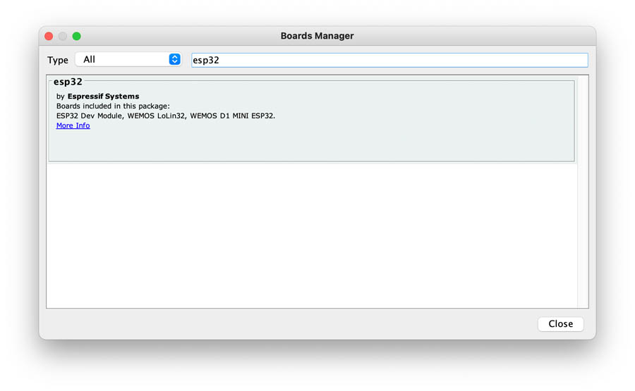
- Enter one of the release links above into Additional Board Manager URLs field. You can add multiple URLs, separating them with commas.
- Open Boards Manager from Tools > Board menu and install esp32 platform (and don’t forget to select your ESP32 board from Tools > Board menu after installation).
I executed all of them.
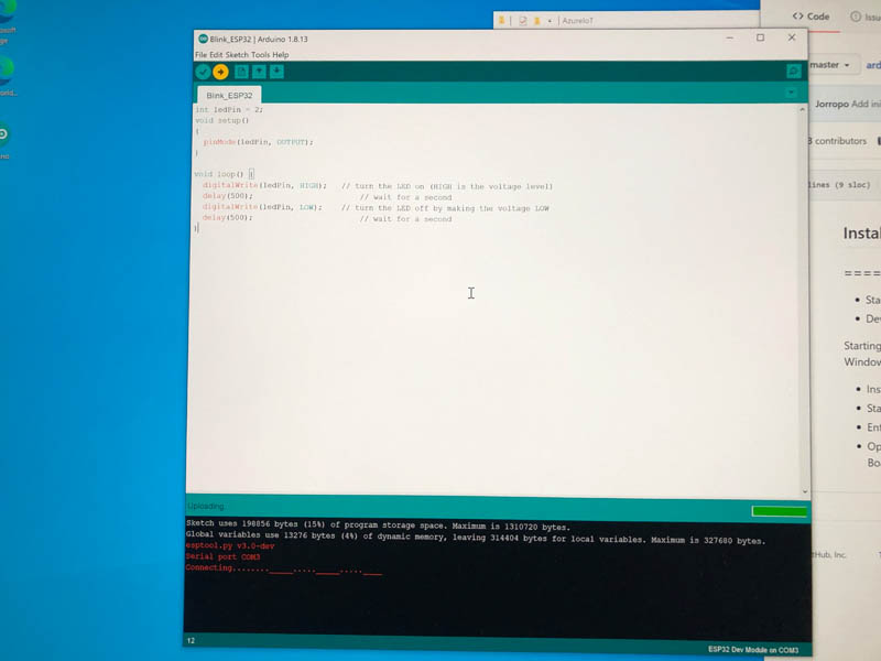
Before we get to uploading sketch & playing with LED, we need to make sure that the board is selected properly in Arduino IDE. Open Arduino IDE and select ESP32 Dev Module option under your Arduino IDE > Tools > Board menu.
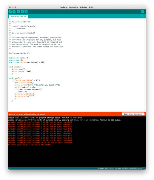
Uploading the hello echo code failed.
After many attempts to solve this issue I decided to switch to Windows bootcamp. I used the same installation guide.
First install the ESP32 board.
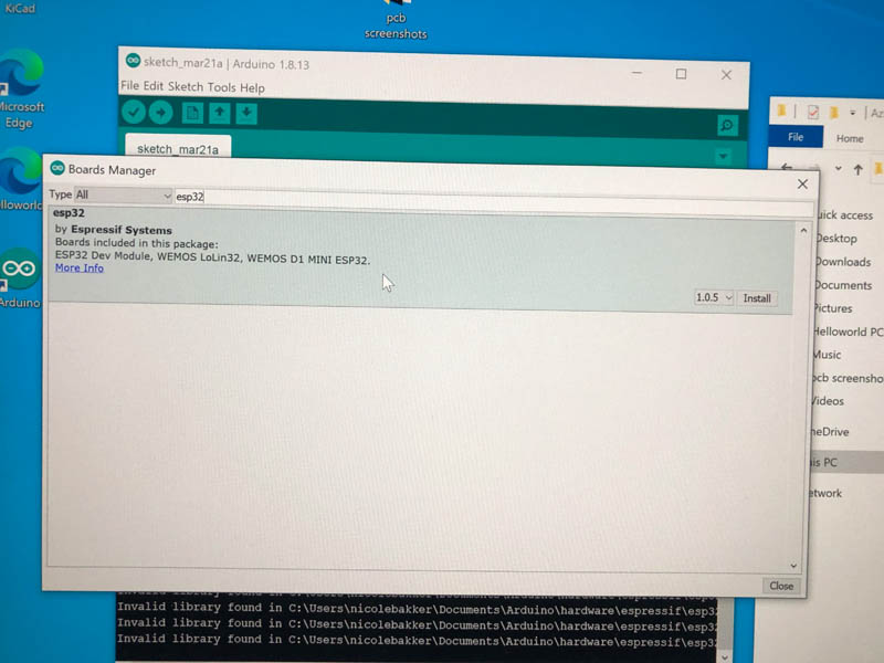
And follow the steps for adding the ESP32 board and setting the port.
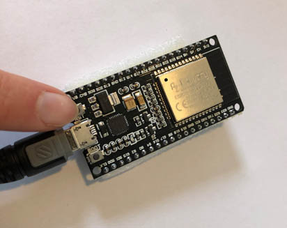
Open Arduino IDE and select ESP32 Dev Module option under your Arduino IDE > Tools > Board menu. Now, plug your ESP32 development board into your computer via micro-B USB cable. Once the board is plugged in, it should be assigned a unique COM port. On Windows machines, this will be something like COM#, and on Mac/Linux computers it will come in the form of /dev/tty.usbserial-XXXXXX. Select this serial port under the Arduino IDE > Tools > Port menu.
Then open the .ino Blink program:
int ledPin = 2;

void setup()
{
  pinMode(ledPin, OUTPUT);
}

void loop() {
    delay(500);
    digitalWrite(ledPin, HIGH);
    delay(500);
    digitalWrite(ledPin, LOW);
}
Upload the Blink program to the board.
This resulted in a fatal error.
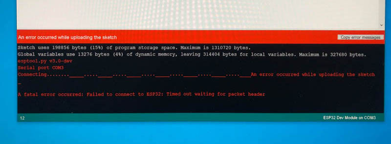
A fatal error occurred: Failed to connect to ESP32: Timed out waiting for packet header
In the Troubleshooting section of the tutorial, it says: “This is a common problem and it means that your ESP32 is not in flashing/uploading mode. You can follow below steps to fix this problem.”
- Make sure that you have selected proper COM port, upload speed to 115200 or lower and board as ESP32 Dev Module.
- Hold-down the BOOT button in your ESP32 board.
- Press the Upload button in the Arduino IDE to upload a new sketch.
- When you see the Writing at 0x00001000… (100 %) message after Connecting…. message in your Arduino IDE log, release the finger from the BOOT button.
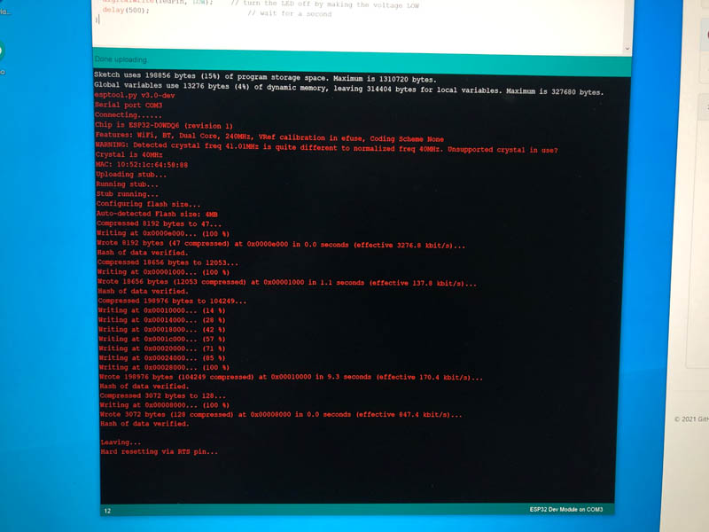
- After that, you should see the Done uploading
Alright! First I tried lowering the upload speed to 115200.
“The upload speed is selected to 921600 by default. Try lowering it to Upload Speed : 115200 as many users complained about getting espcomm_sync failed error when trying to upload the sketch at 921600 speed.”
That didn’t solve the problem. The board doesn’t do anything.
On to the next recommendation: “in short, you need to press and hold the BOOT button before hitting the Upload button and keep it pressed until Arduino IDE starts writing to ESP32.”
The page from Random Nerd Tutorials recommends the same: ‘One of the ways to solve this is holding-down the “BOOT/FLASH” button in your ESP32 board while uploading a new sketch at the same time.’ They also provide a way to prevent this next time, by soldering a connection between two components. I might do that in the future, for now it’s a bridge too far.
Pressing the BOOT button was succesful! There is some activity!
The code is uploaded, however, my LED is not blinking yet. The tutorial says the following: “Once the code is uploaded, LED will start blinking. You may need to tap the EN button to get your ESP32 to begin running the sketch.”
On my board, there is no EN button for ENABLING the sketch. Instead: RST and BOOT. Shall I press RESET? Forum question: Is an RST pin (or button) the same as EN pin (or button) on ESP32 Boards? Answer: yes. So that’s the one I can press.
The LED blinks once while pressing RST. This is just a response to pressing the button, not activating the actual program. Still, the program doesn’t run.
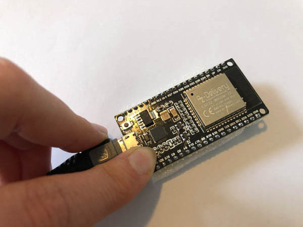
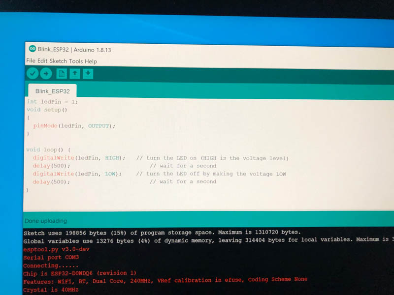
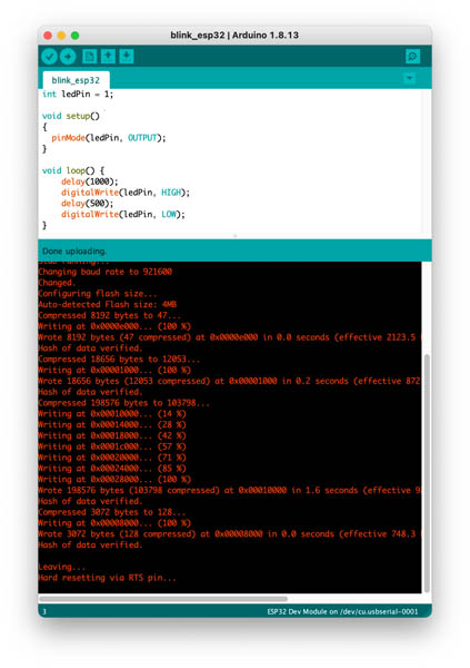
And suddenly, I found the solution: THERE IS ONLY ONE LED ON THIS ESP32 BOARD instead of two! See image below.
So simply changing the ledPin to 1 solved the problem!
int ledPin = 1;

void setup()
{
  pinMode(ledPin, OUTPUT);
}

void loop() {
    delay(500);
    digitalWrite(ledPin, HIGH);
    delay(500);
    digitalWrite(ledPin, LOW);
}
Running the code with the correct BOOT and RST button procedure.
Success!
ESP32 on Mac
Next, I switched back to Mac to try the same procedure.
And uploaded the same program.
Success! Now we can continue with other programming environments and languages.
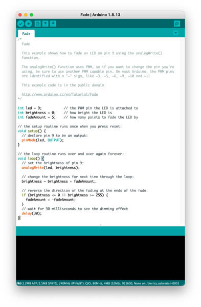
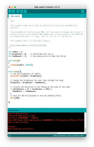
Fade program on ESP32
Change the standard Arduino program to ledPin.
Other programming language: C++
W3Schools published a C++ Introduction. They say that C++ is a cross-platform language that can be used to create high-performance applications. It is an object-oriented programming language which gives a clear structure to programs and allows code to be reused, lowering development costs. As C++ is close to C# and Java, it makes it easy for programmers to switch to C++ or vice versa. A Guru99 tutorial says the following: As it is one of the fastest programming languages, C++ is widely used in programming of game development engines. C++ can easily manipulate hardware resources and it can also provide procedural programming for CPU intensive functions.
Visual Studio Code IDE
To use Visual Studio Code as an IDE for embedded programming of microcontrollers, we first have to install a Visual Studio Code Extension on the Marketplace. There are three options for the ESP32:
- ESP-IDF
- PlatformIO IDE
- ESP-Engine
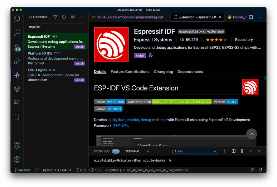
The ESP-IDF Programming Guide can be found here. Guidance on installing and using PlatformIO on Visual Studio Code is provided here by Random Nerd Tutorials. I’ll start with PlatformIO.
When do you use this IDE? Before we start, I’d like to know on what occasions we would like to use an IDE other than Arduino. “The Arduino IDE works great for small applications. However, for advanced projects with more than 200 lines of code, multiple files, and other advanced features like auto completion and error checking, VS Code with the PlatformIO IDE extension is the best alternative.” - Random Nerd Tutorials
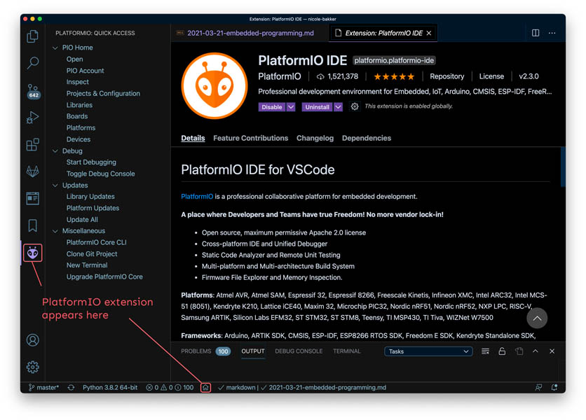
After installation of the Plugin, a new icon appears in the side bar.
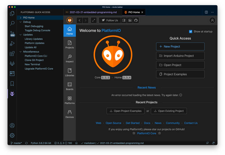
You can press Ctrl+Shift+P or go to View > Command Palette… to show all the available commands. To create a New Project, click on the PlartfomIO Home icon. Click on + New Project to start a new project.
Now the Project Wizard window appears. I entered the following settings for uploading the blink program.
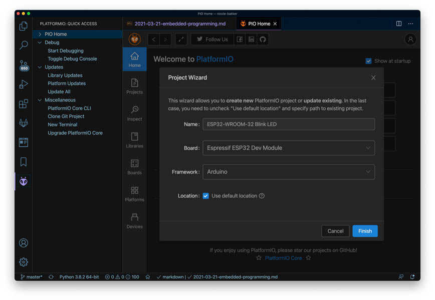
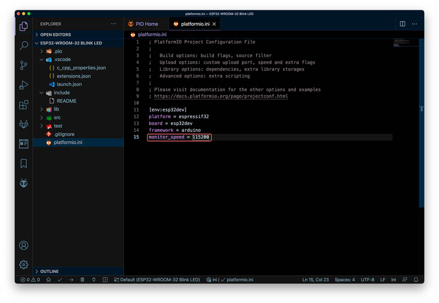
Open the platformio.ini file and add monitor_speed = 115200 to the code. This is the “baut rate” to reduce the upload speed (same step as in Arduino IDE).
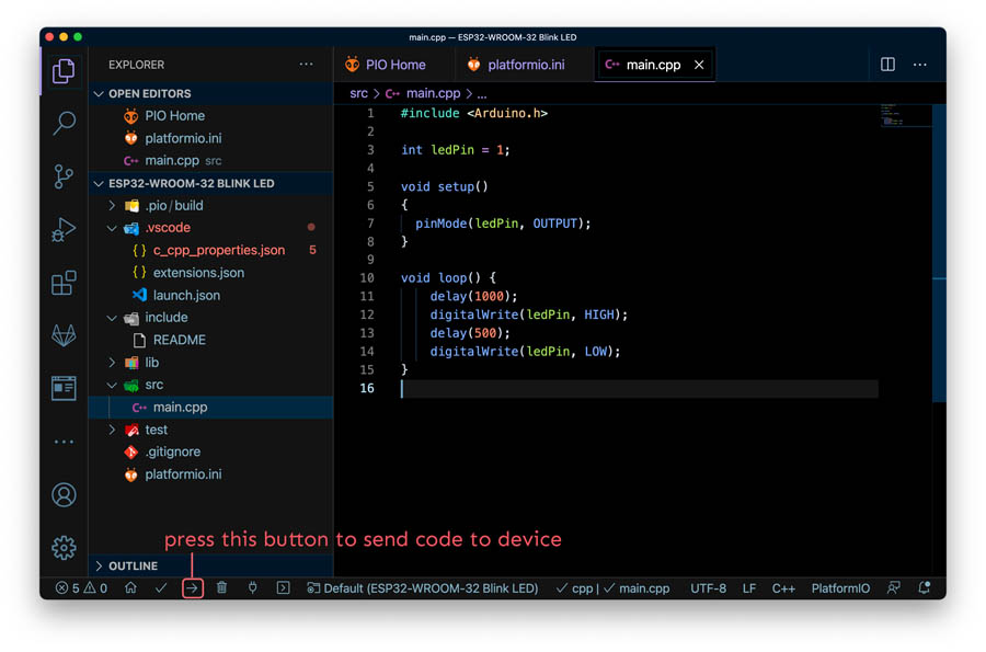
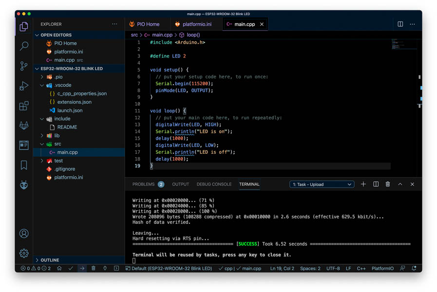
Paste the Arduino code used in the Arduino IDE in the main.cpp file and press send.
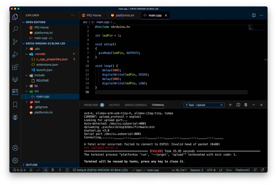
The program failed.
Next, I tried to change the code to the code example provided by Random Nerd Tutorials. This also failed.
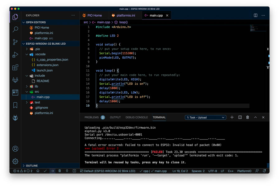
Next, I pressed the BOOT button while uploading the code and it worked!
I’m really happy that I was able to succesfully install Visual Studio Code and make a program blink on the ESP32. It also succeeded to run my first python script in this environment (for project managment of this website, image processing). Python and IDLE don’t work in the terminal on my Mac due to known issues with Big Sur. Being able to run code with the Visual Studio Code IDE opens up more possibilities in the future.
Explore more like this
Week 17 Invention, Intellectual Property and Business Models
After acing through the technical assignments of Fab Academy, the last two weeks have a lighter load so we can focus on the final project. But this does not mean...
Week 16 Applications and Implications
Propose a final project masterpiece that integrates the range of units covered, answering: