Week 4 Electronics Production
This is the first week we're working with electronics! A summary of the topics is given below.
Summary
This week we made a circuit board. We learned to work with a small milling machine and to solder the parts of a PCB.
Assignments
Group assignment
- Characterize the design rules for your PCB production process: document feeds, speeds, plunge rate, depth of cut (traces and outline) and tooling.
- Document your work (in a group or individually)
Individual assignment
- Make an in-circuit programmer by milling and stuffing the PCB, test it, then optionally try other PCB fabrication process.
Learning outcomes
- Describe the process of milling, stuffing, de-bugging and programming
- Demonstrate correct workflows and identify areas for improvement if required
Project management
In preparation of this week’s task, I’m planning the following steps in spiral development:
| Spiral | Tasks | Time |
|---|---|---|
| 1 | Characterize the small milling machine (group assignment) | 4 hours |
| 2 | Mill the PCB board | 2 hours |
| 3 | Soldering | 2 hours |
| 4 | Testing the PCB | 15 min |
| 5 | Documentation | 8 hours |
Let’s get started!
This week’s results
Group assignment
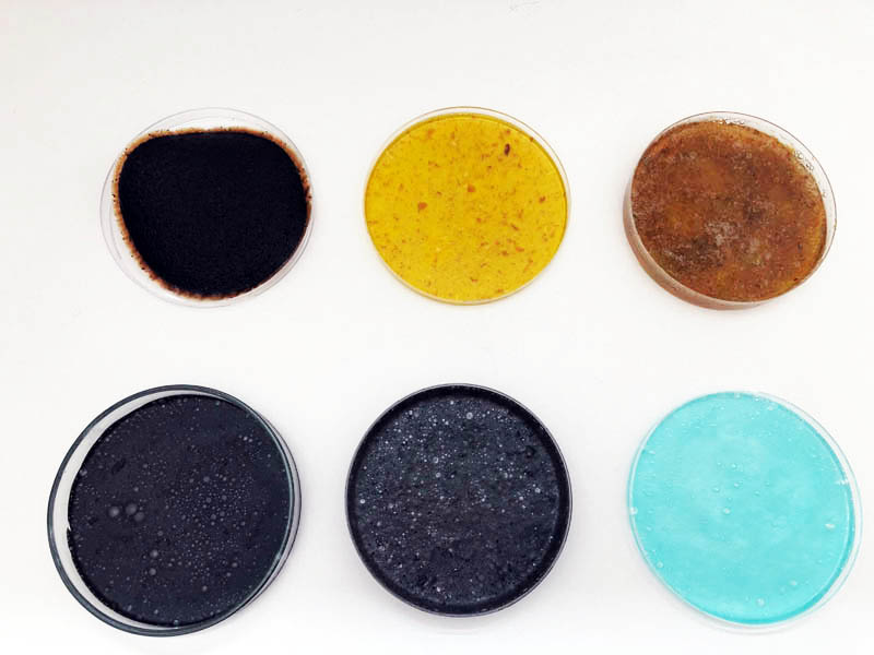
PCB
PCB other materials: copper
How-to’s are below!
Group assignment
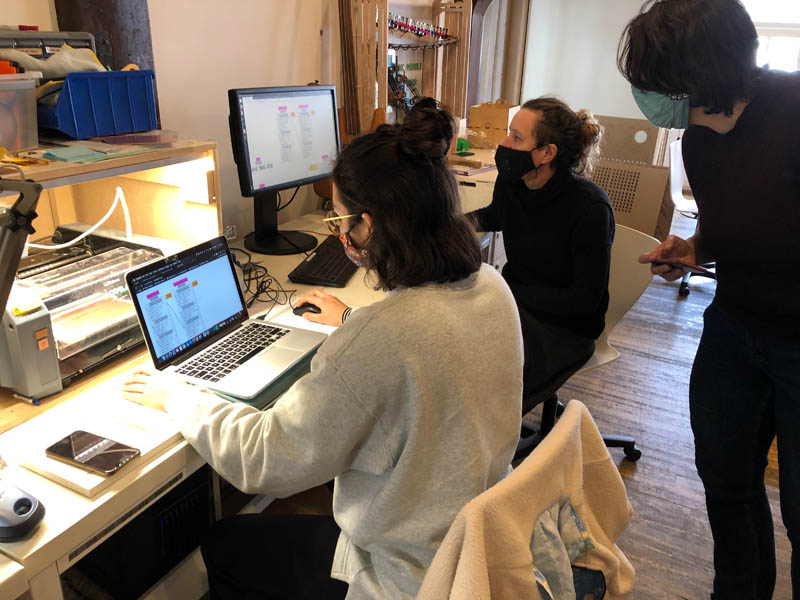
This week, I completed the group assignment with Loes, Lucia and Paula at FabLab Waag.
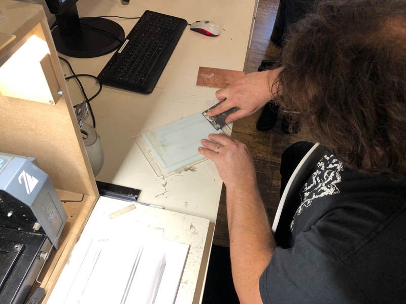
Sacrificial layer
Before we start, Henk shows how to replace the sacrificial layer.
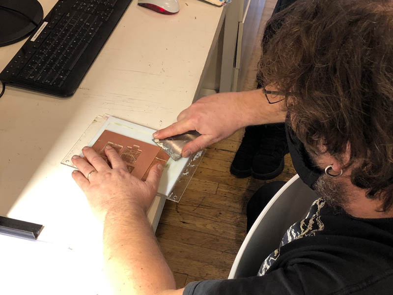
It is very important to create a flat surface, because otherwise the PCB’s will not come out nicely.
Now we’re ready to go!
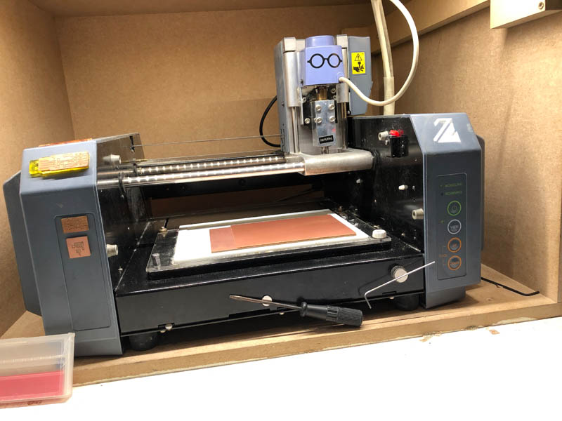
Milling
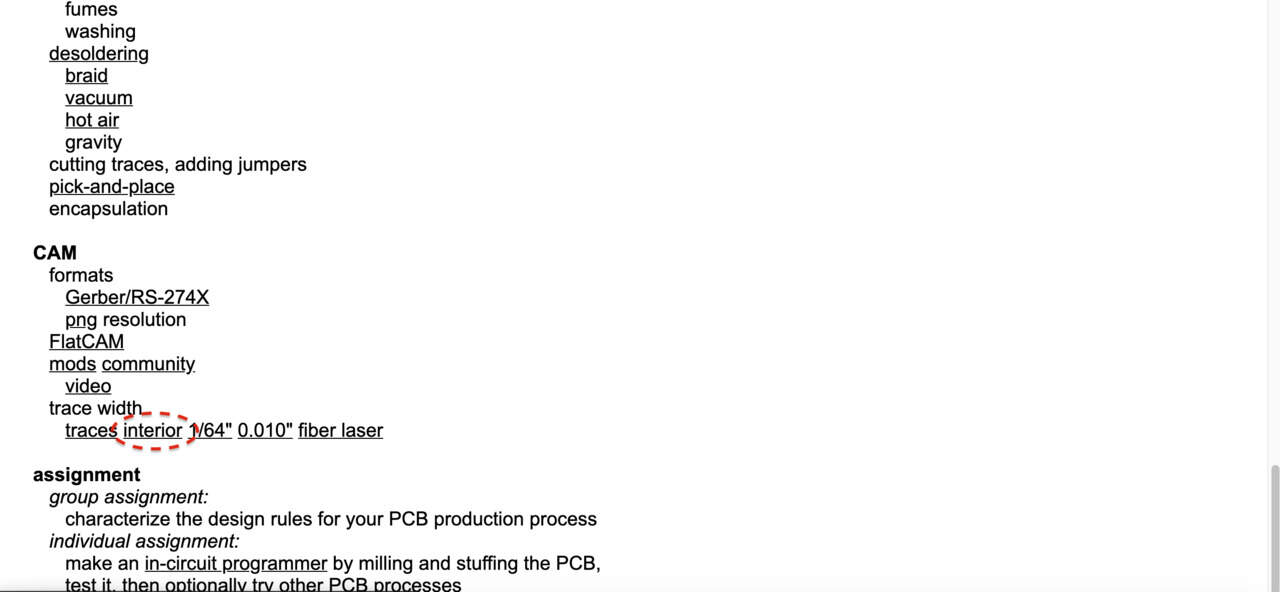
Start with downloading the traces and interior files from this week’s class page. You can find it here:

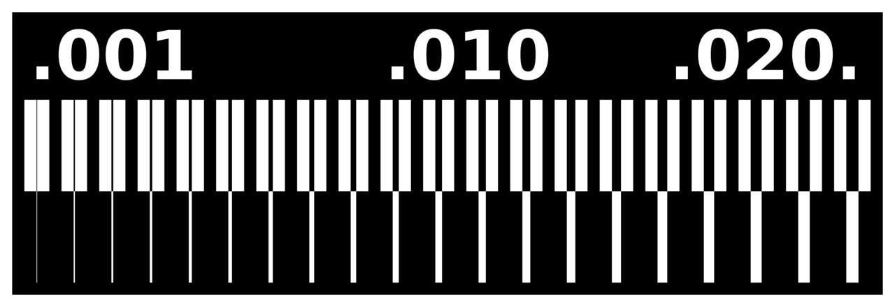
This is the tool we’ll be using to determine the precision of the end mill.
And this will create the outline:

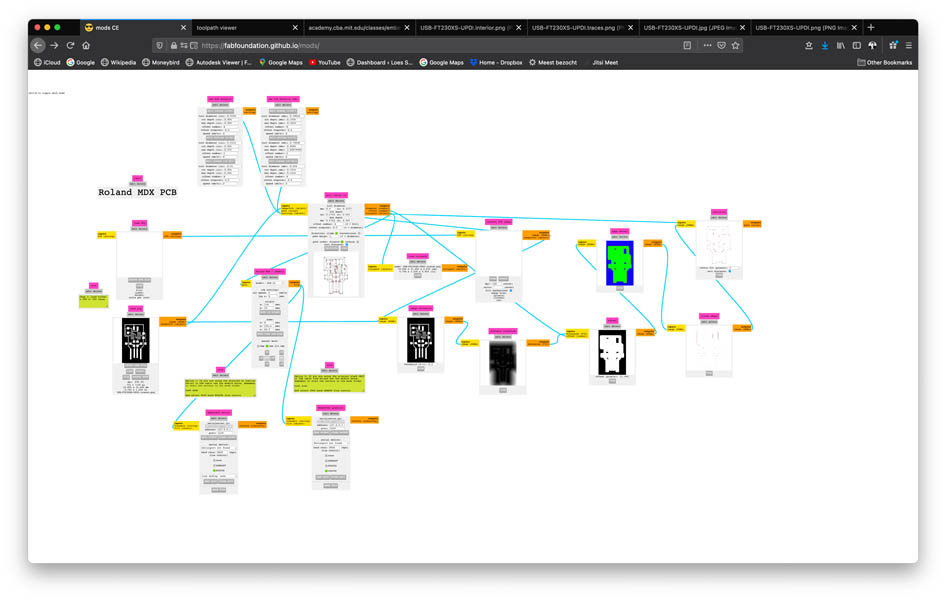
Open mods in the browser, right click somewhere in the canvas, navigate to programs, open programs then Roland MDX mill and select the PCD option.
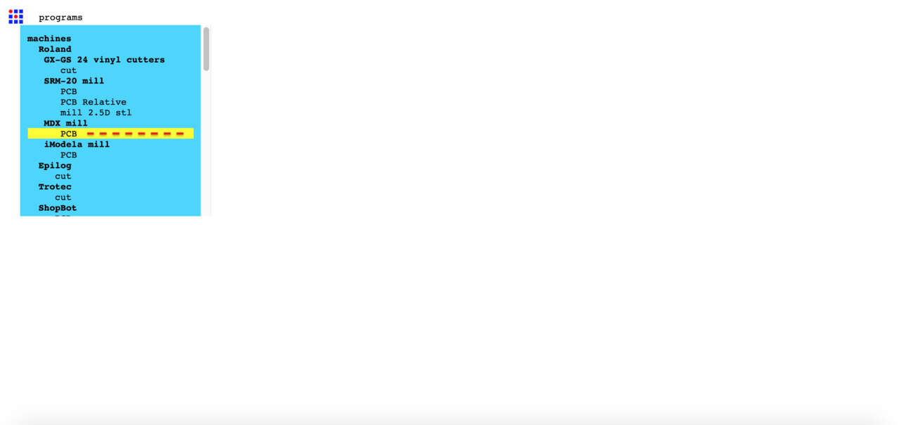
This is what the canvas looks like:
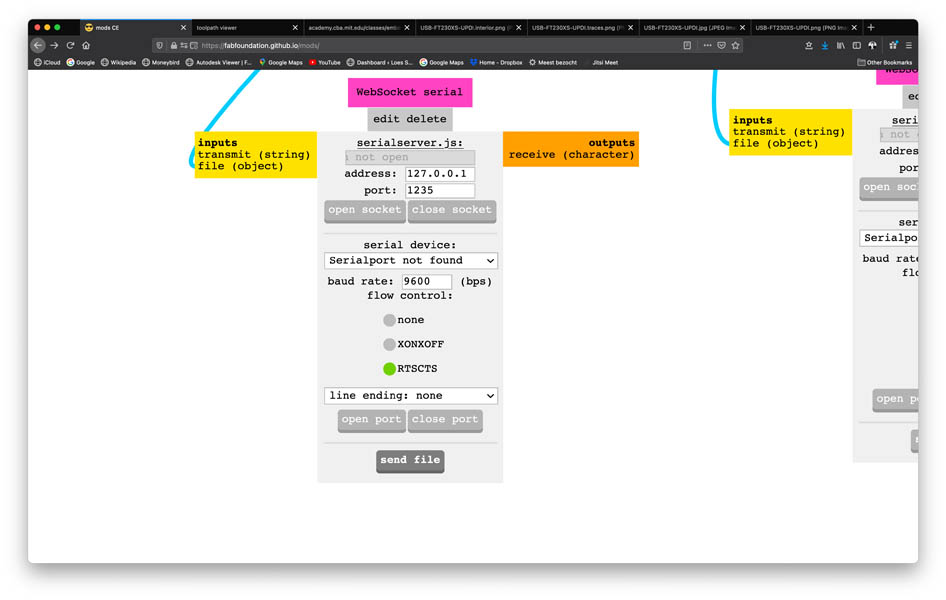
Navigate to WebSocketSerial block below and close both port/socket and open them again, to work around a bug at the PCB milling machine at Waag.
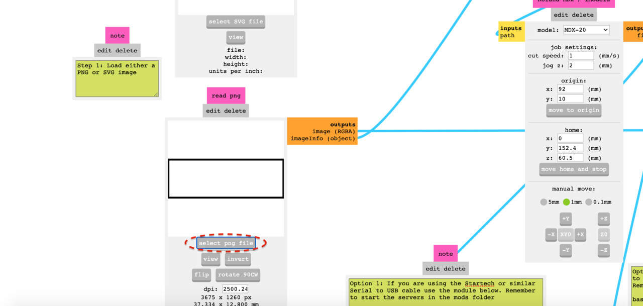
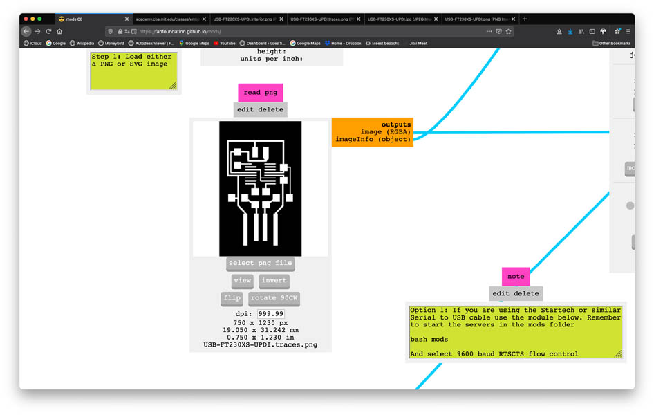
Then upload the traces file in the read png block.
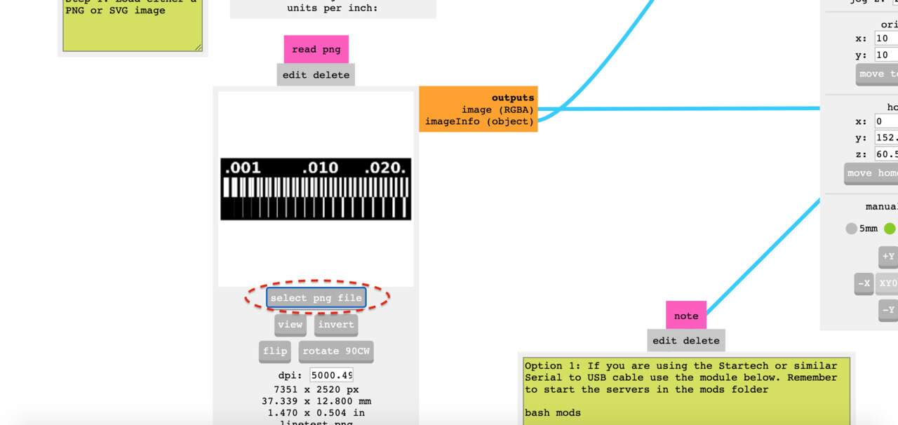
Check if the DPI is at a minimum of 1000 to avoid inaccurate traces.
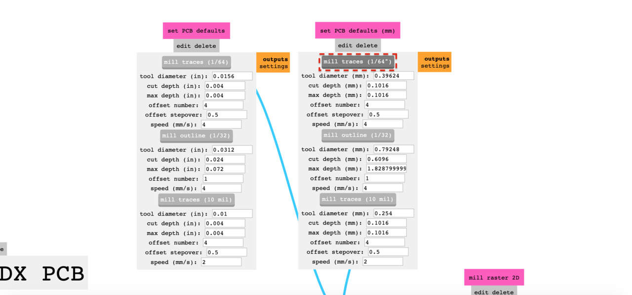
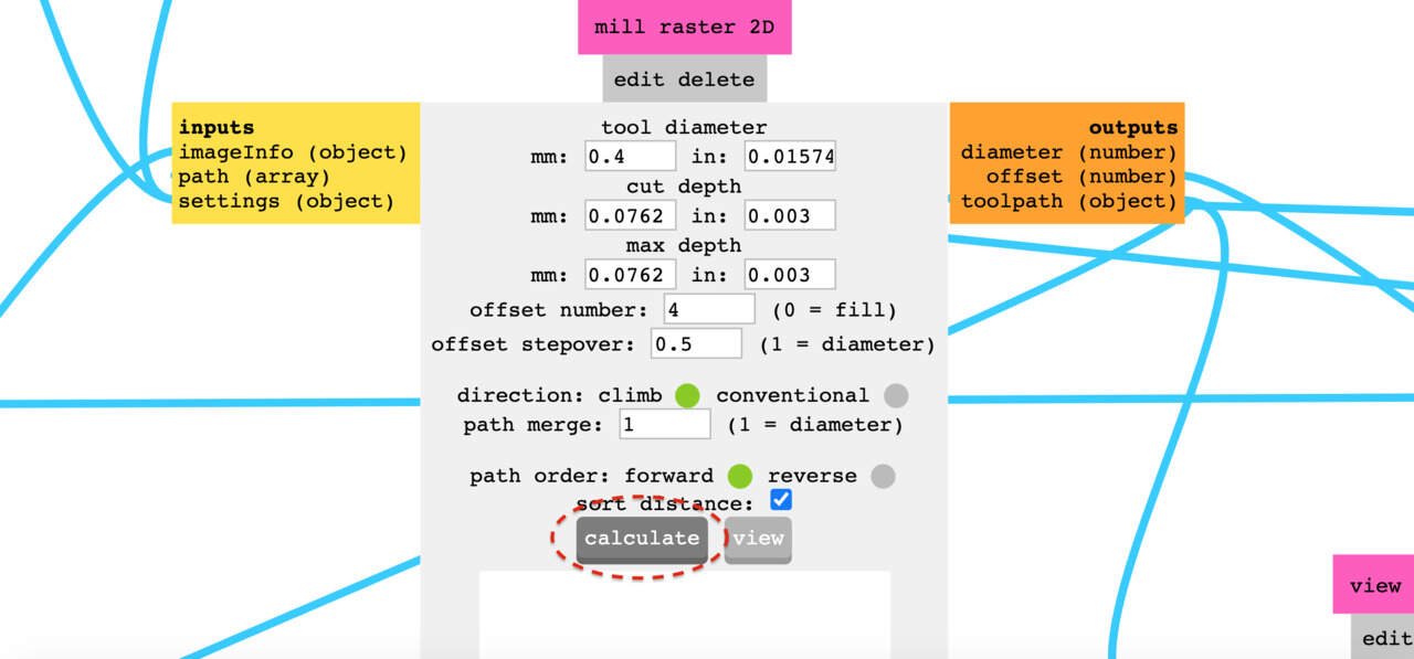
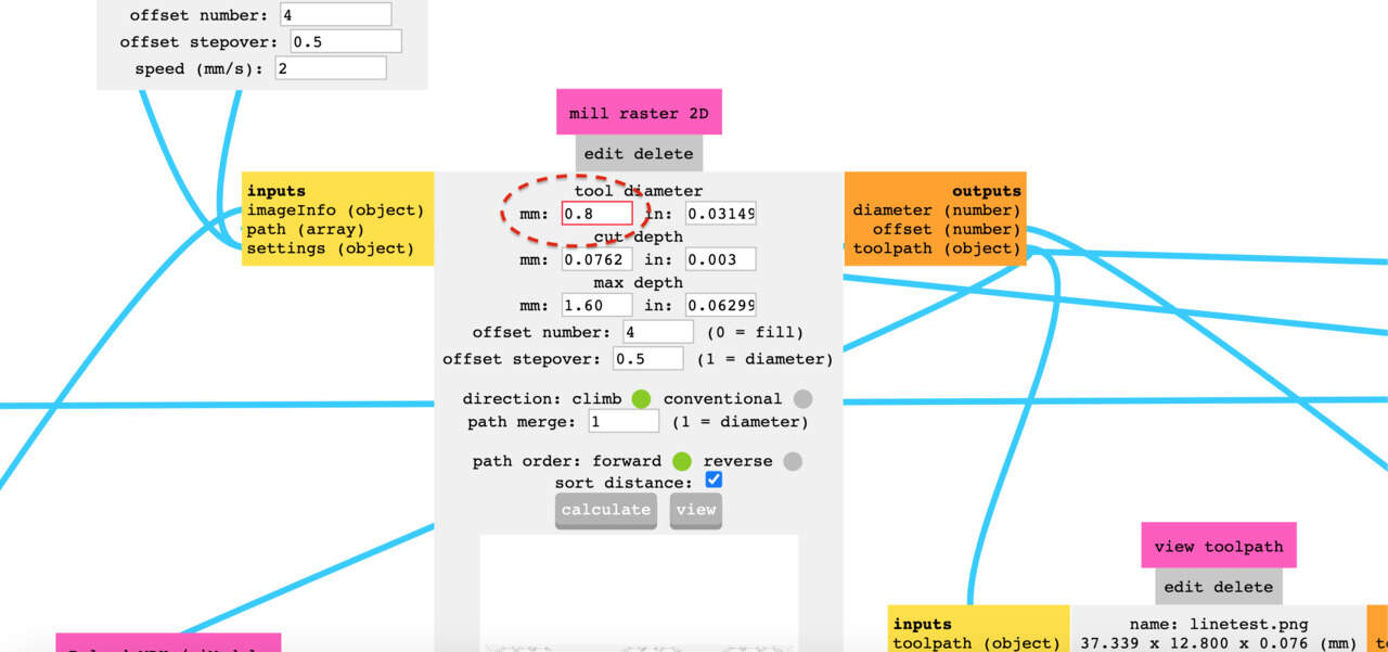
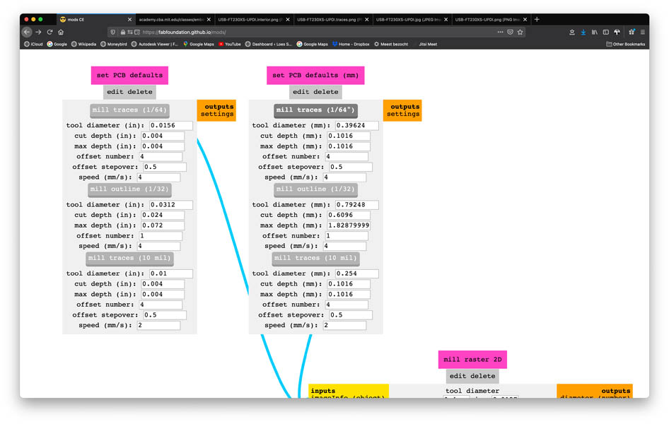
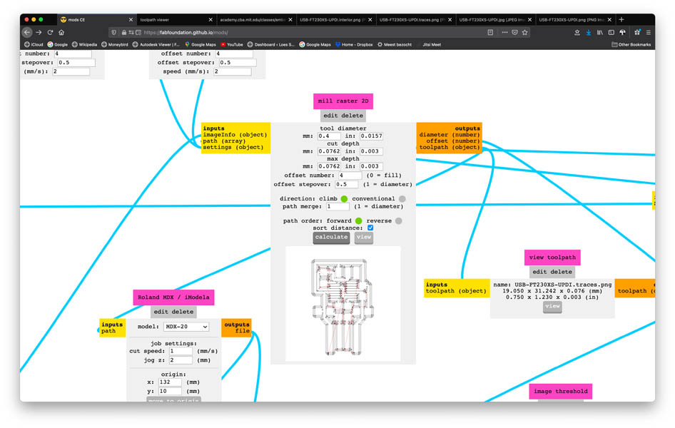
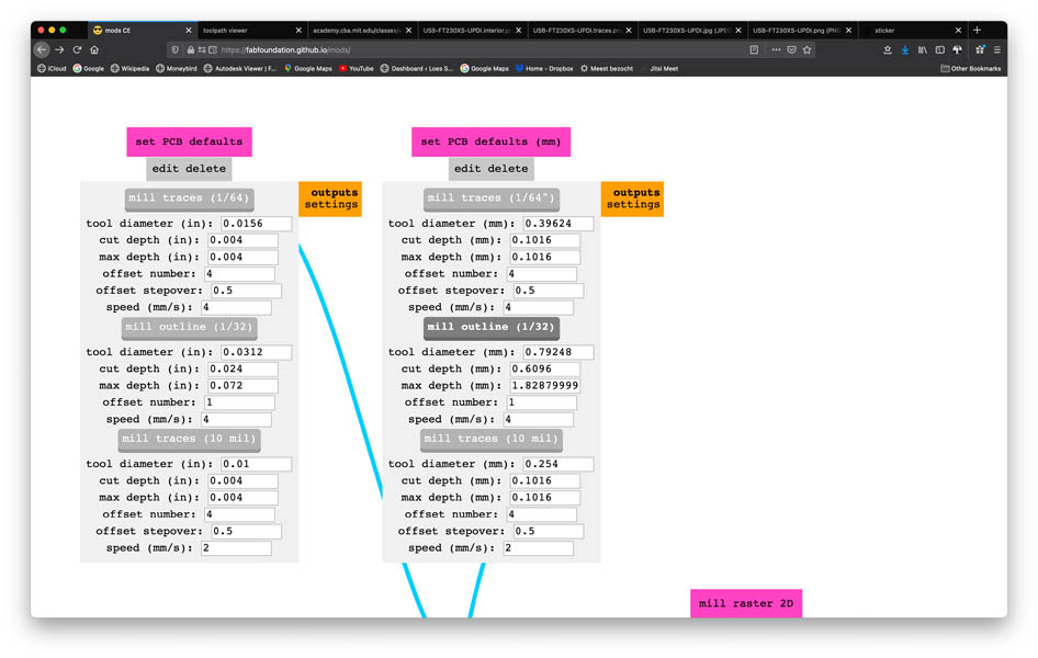
Go to PCB window press mill traces (1/64") . This feeds the Mill Raster 2D window.
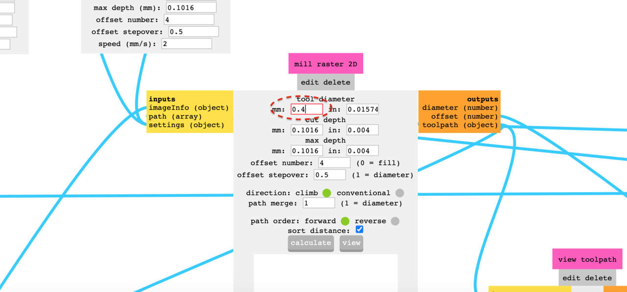
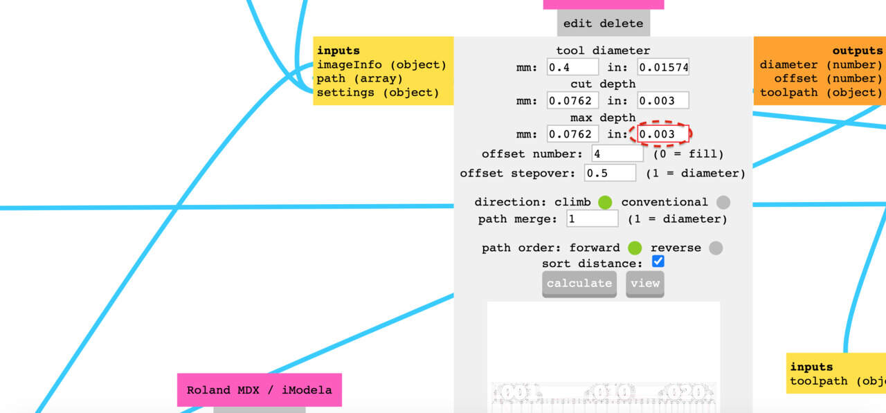
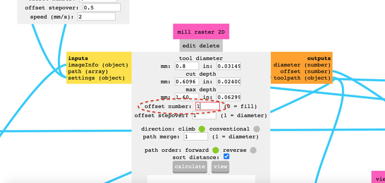
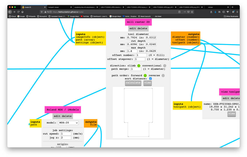
In Mill Raster 2D fill in the tool diameter: 0.4 mm.
Set the cut depth: 0.003 inches.
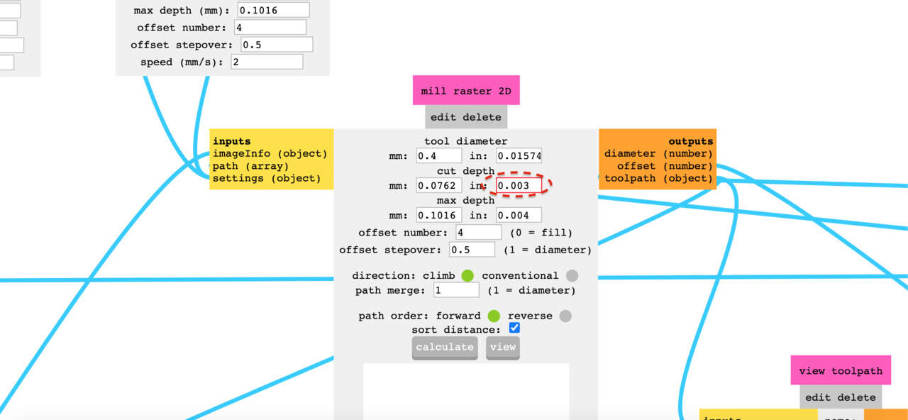
Be aware of the inches/mm and change the max cut depth: 0.003 inches. This is the same as the depth since we are making traces.
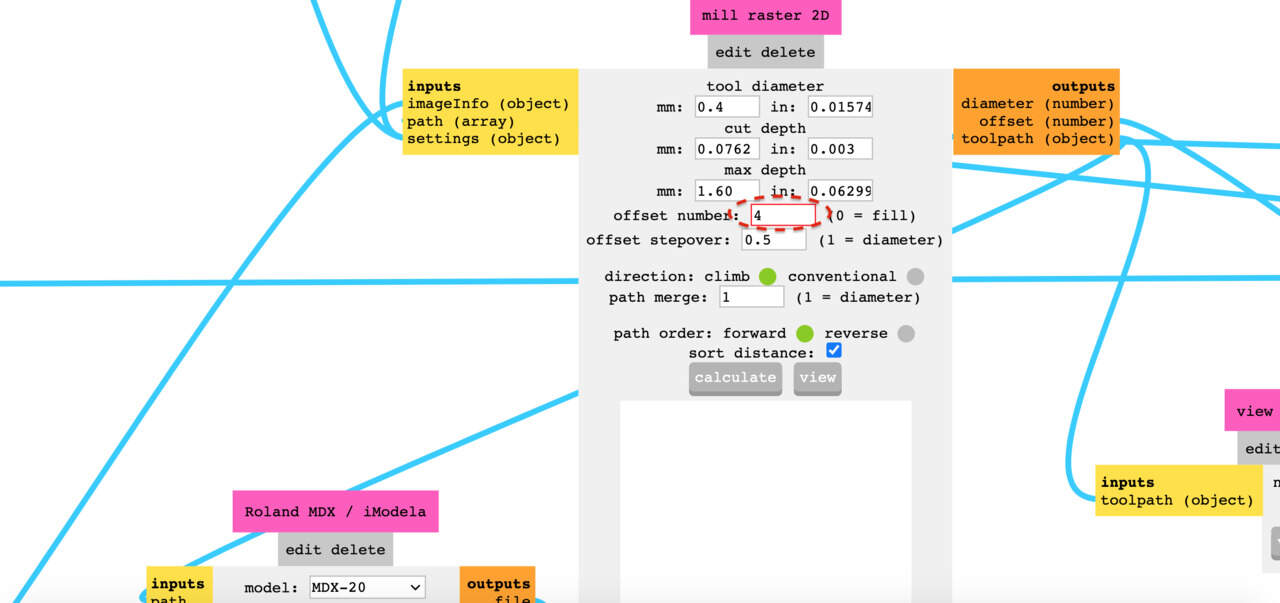
Check offset: 4 otherwise the lines are too thin (offset means the amount of lines he tried to put in there, if it doesn’t fit he goes 3, 2, or even just one time), but if you offset:0 it will take away all the excess copper.
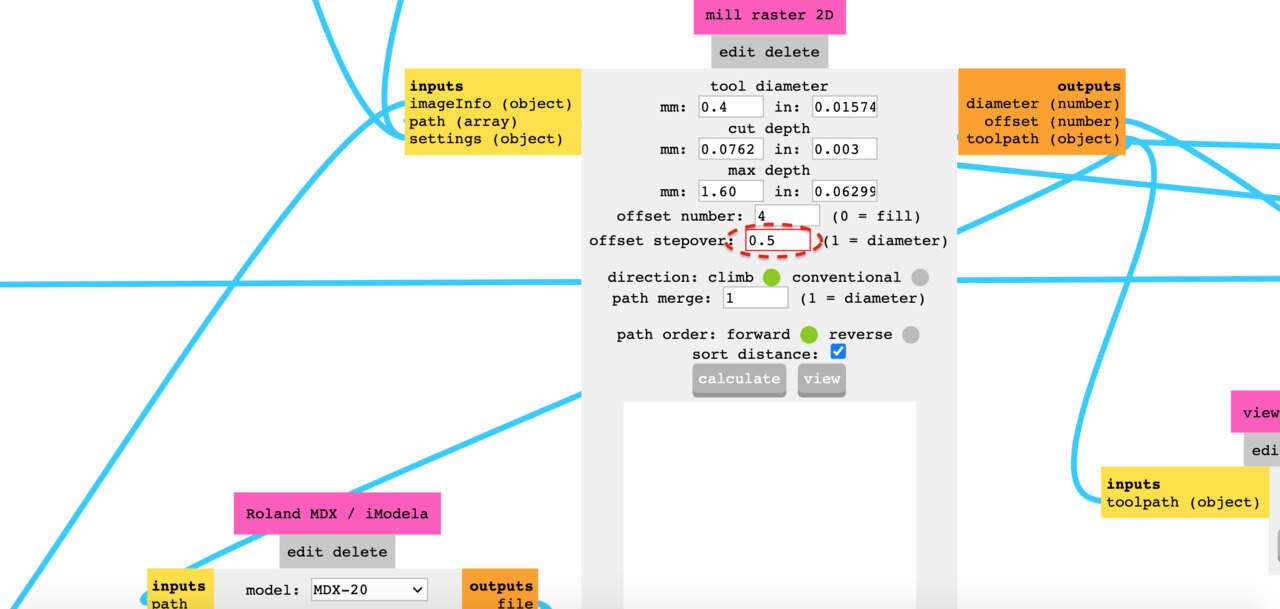
Offset stepover: 0.5 this means it will start the next line only half the diameter further, this is to avoid bumps in the traces.
Then there is also path order which seems arbitrary, probably useful for real PCB creators and Direction which has everything to do with how the flute (wings) of the mill chop copper off, either down or up towards the travel path.
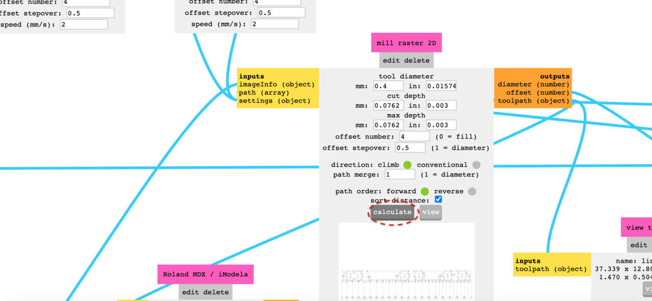
Press calculate for the server to translate this .png image to RML (gcode) readable for the Roland machine.
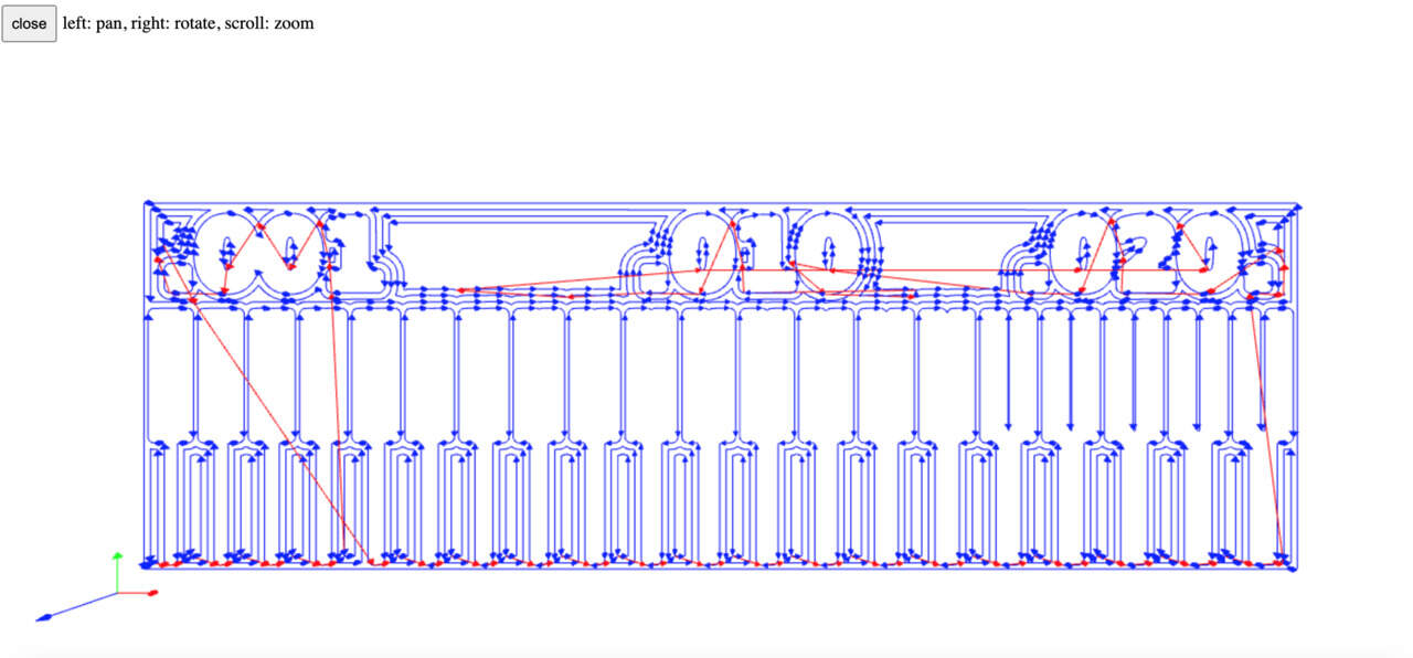
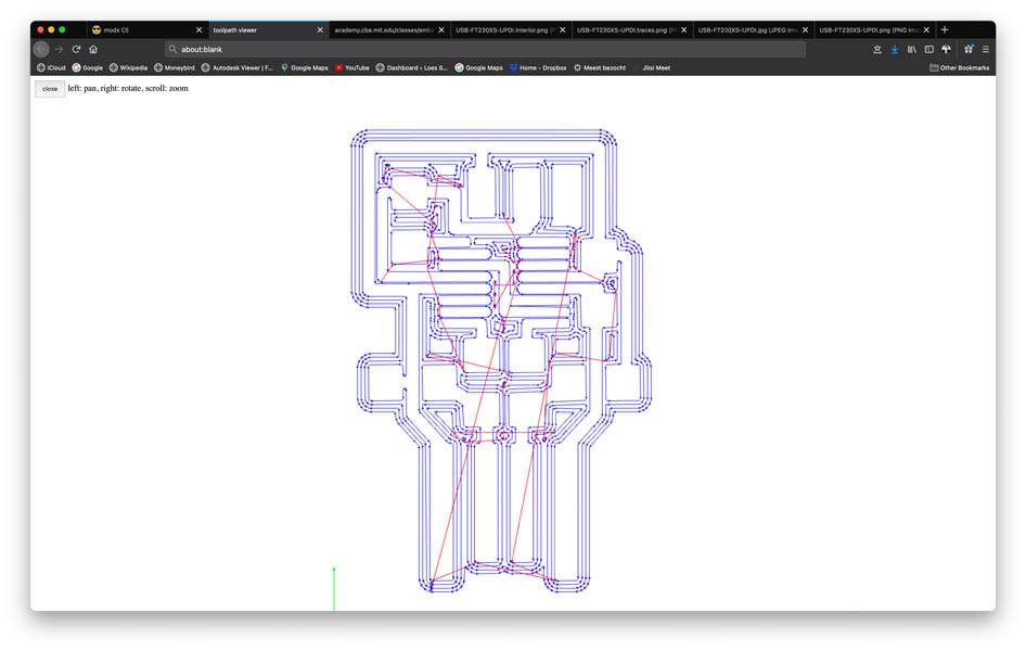
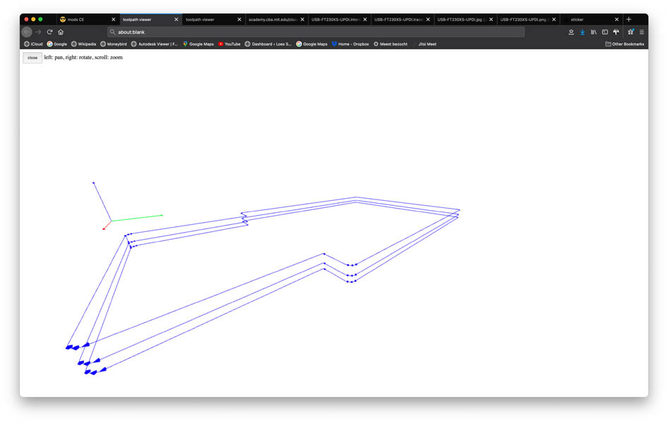
In 3D toolpath viewer click view to open a new tab with the 3D traces, check if the design makes sense.
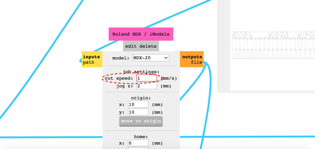
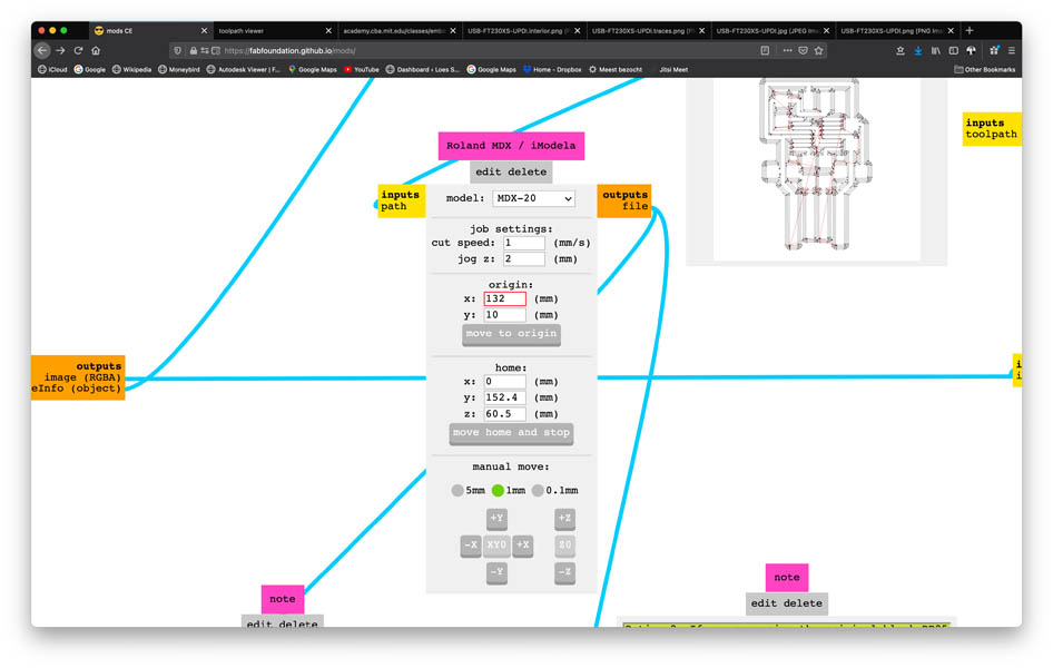
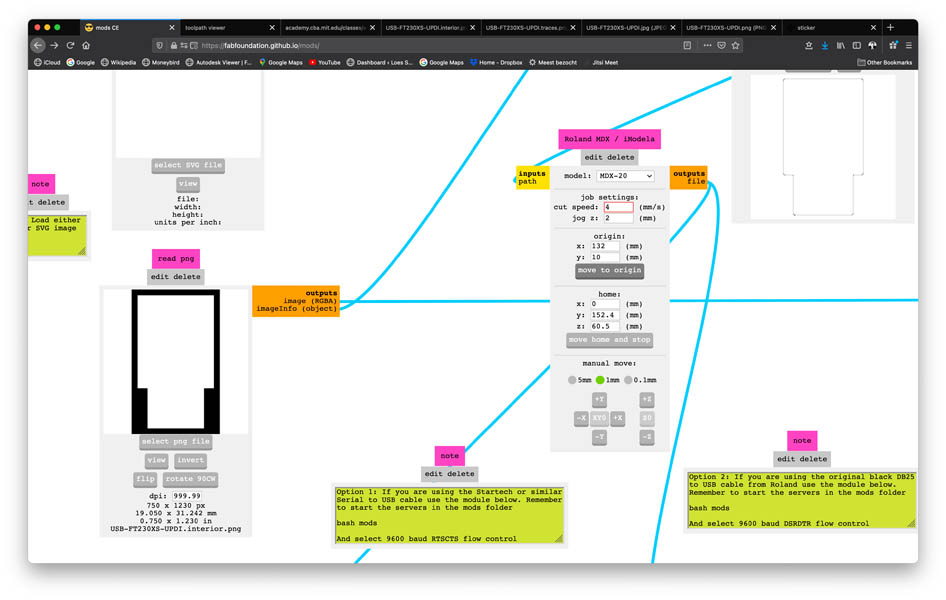
Go to the Roland MDX/iModela window and set cut speed: 1 otherwise you will break the tiny 0.04 mill.
Now its time to put the mill in. According to Henk, this is better than meditation.
On the Roland press view twice to move the plate and mill to a workable position, lower the mill a bit with DOWN not to low you still have to be able to take the mill out. With the allan key open the lock (marked blue) while holding the drill so it doesn’t drop and breaks. Place it in the little box (on the left where the good ones are) and get the 0.8 mill from the magnet on the front, place it in as deep as possible for stability. Tight the screw gently, not to strong.
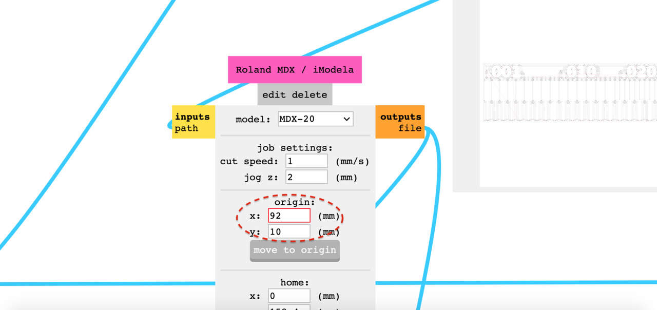
If the end mill is positioned, return to mods. Select an x and y coordinate and click ‘move to origin` to find out where the end mill is.
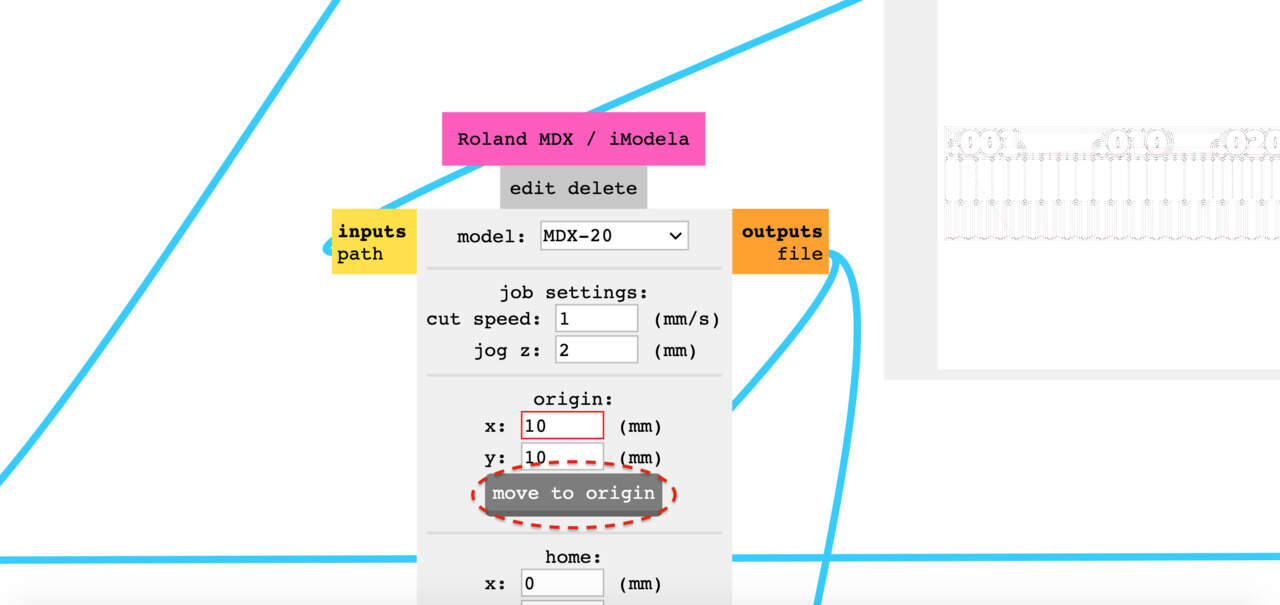
Change that to a position where you’d like the milling process to start. Important: make sure to take a screenshot or picture of this home position.
Navigate to the Mill raster 2D window and hit calculate.
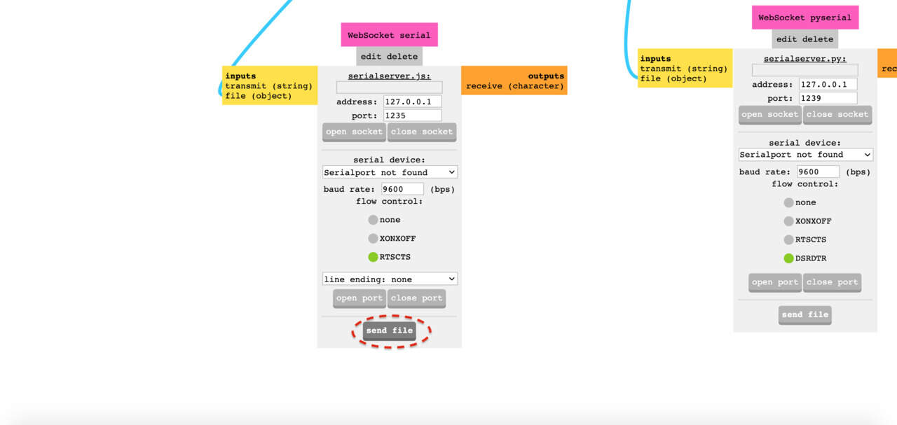
Finally, go to WebSocket serial window and click send file. Roland will mill your file! This takes about 30 minutes. Now you can grab lunch or a coffee :)
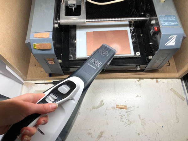
When the milling is ready, use the vacuum cleaner to remove the dust.
Then we can mill the outline. Continue with interior file from this week’s class page. You can find it here:
This image:
Repeat the process and select png file in the read png window.
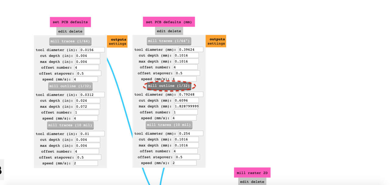
Now select mill outline (1/12) in the set PCB defaults (mm) window.
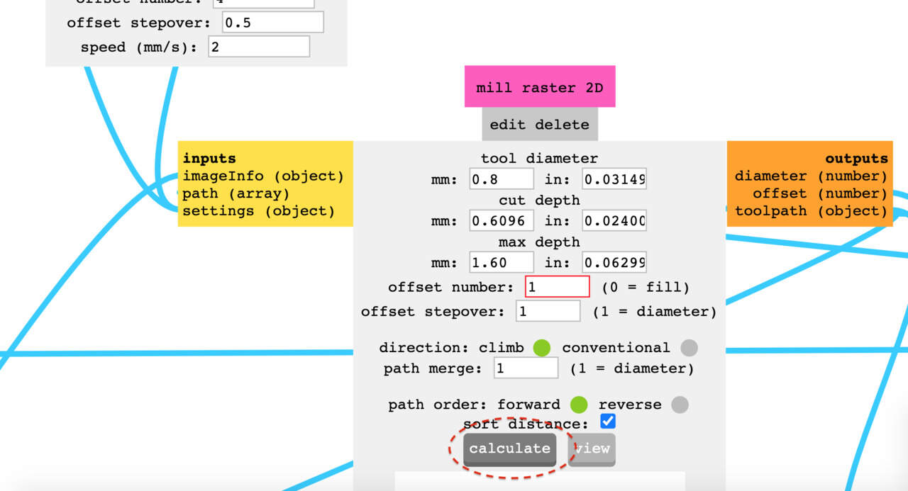
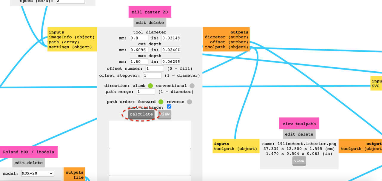
In the mill raster 2D window, set the tool diameter = 0.8 mm.
And change the max depth = 1.60 since we want to cut all the way through the copper material.
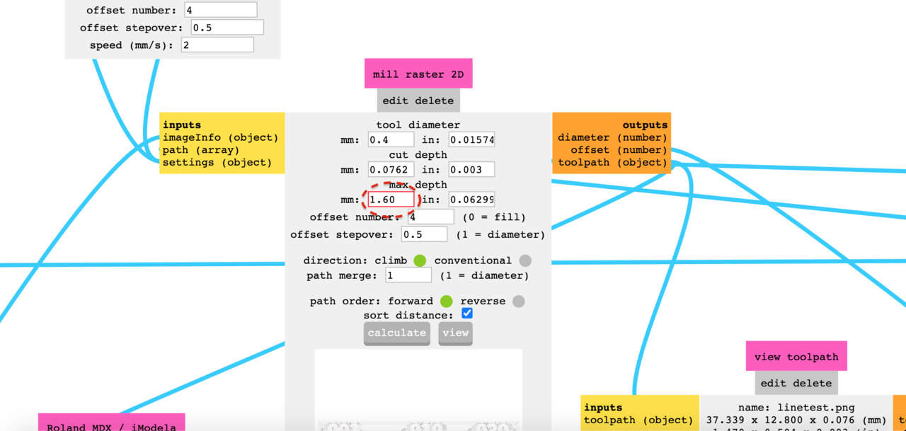
Set the offset number = 1.
Click calculate.
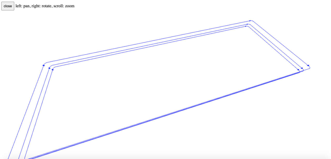
Move to view toolpath and click view.
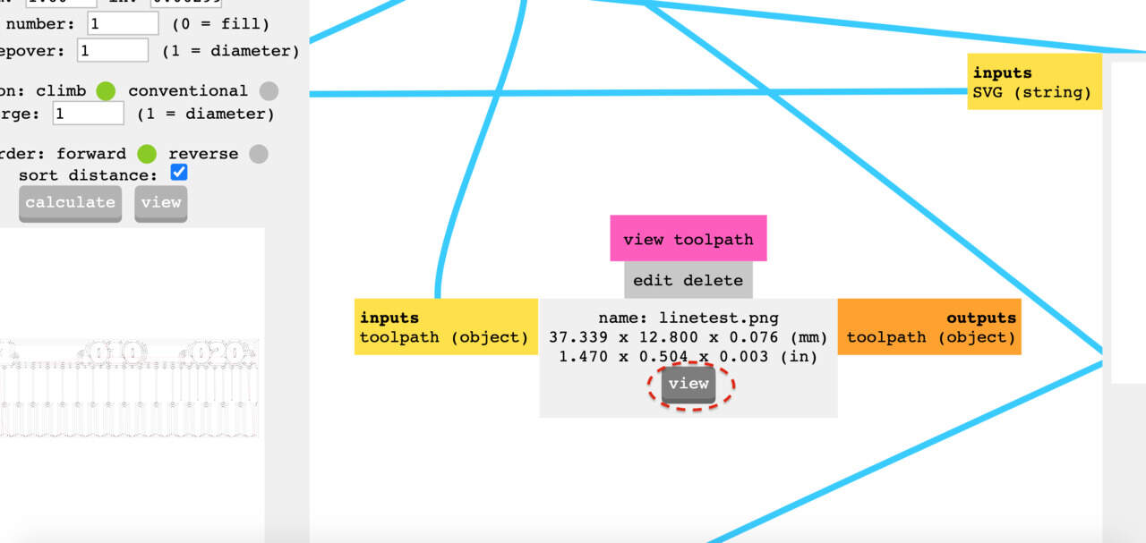
Inspect if the desired paths are created.
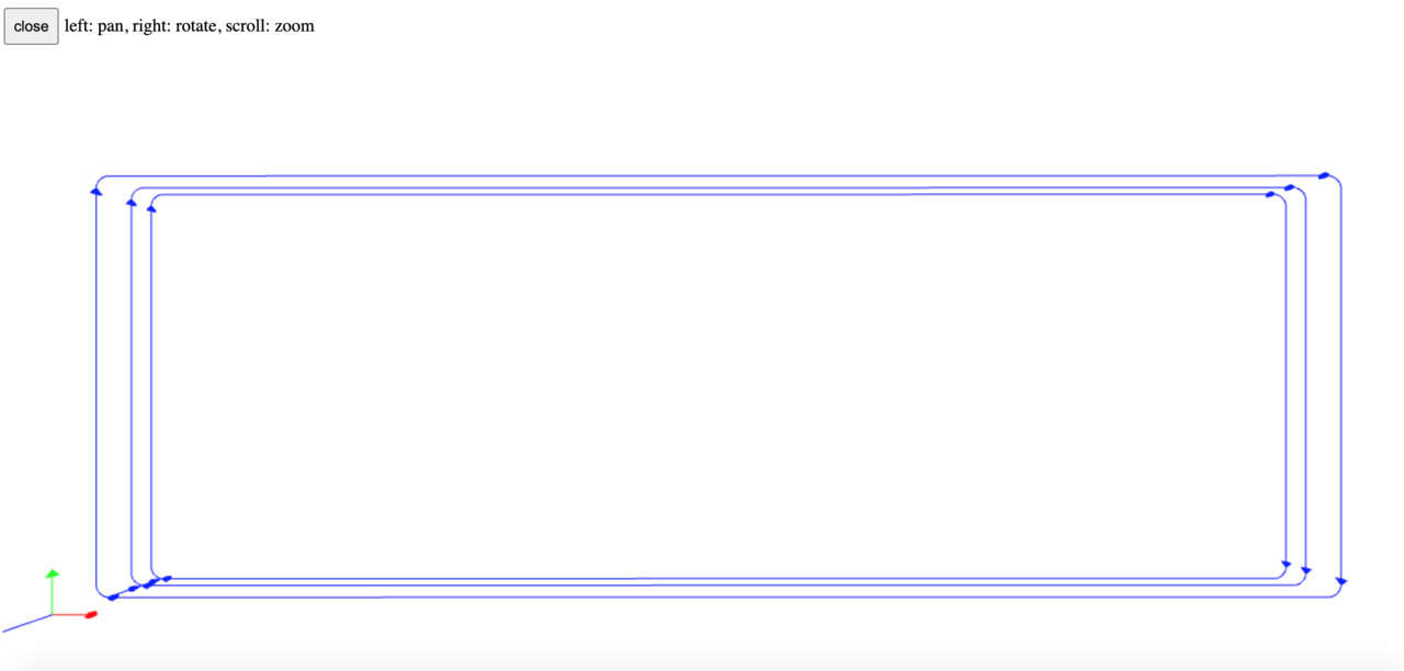
You can also rotate the image.
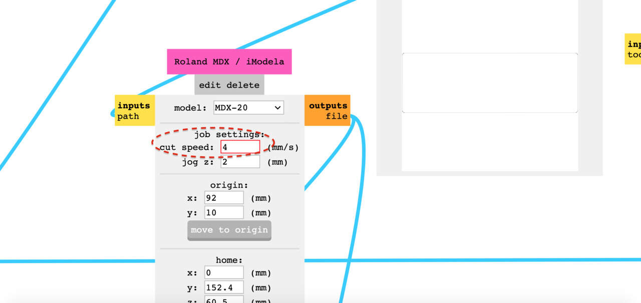
In the Roland MDX / iModela window, change the cut speed = 4 mm/s. This setting is used for cutting al the way through the material.
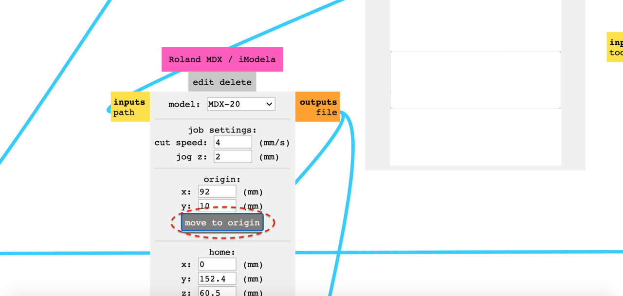
Check if your origin is the same as the traces file and click move to origin.
In the mill raster 2D window, click calculate.
Then navigate to the WebSocket serial window and hit send file. The milling process will now start.
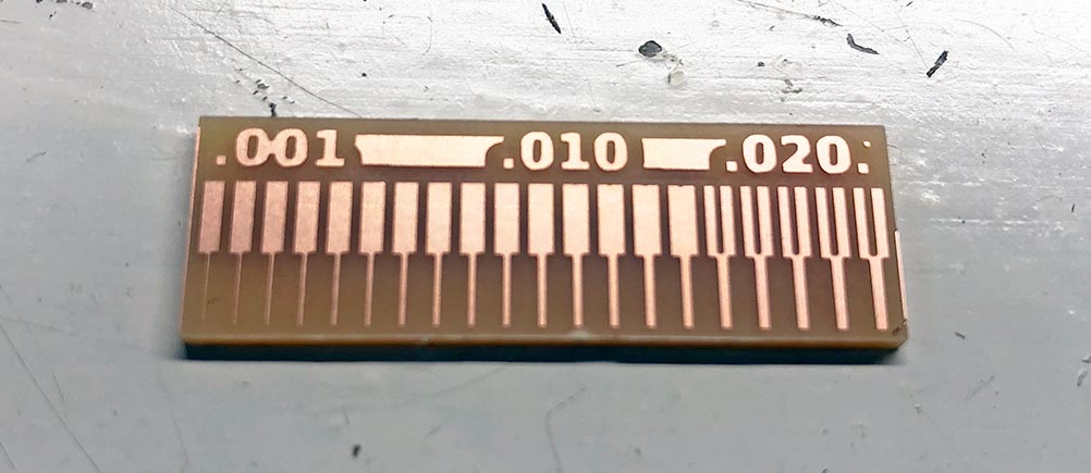
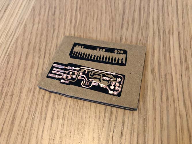
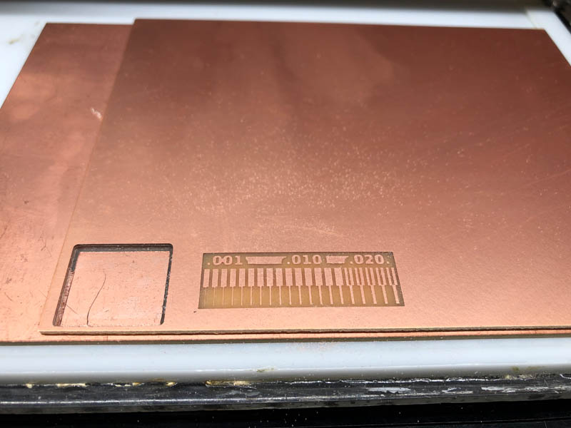
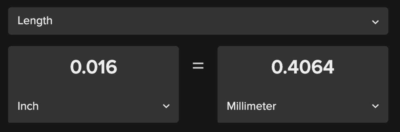
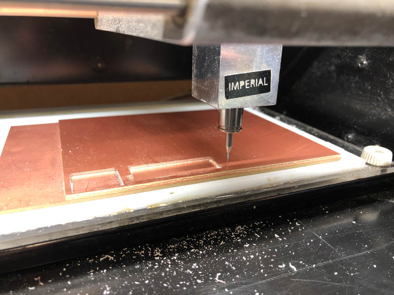
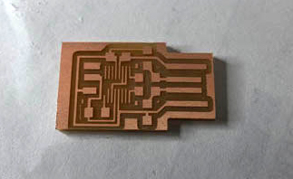
Done! The smallest visible trace is 0.001 inch, as can be seen in the bottom left line of the picture. This is a milling precision of 0.0254 millimeters!
The size of the “pocket” (resembling a tuning fork) is 0.016 inch. To check the precision of the mill, we convert inches to millimeters. This is approximately 0.4 mm, corresponding to the size of the mill.
Individual assignment
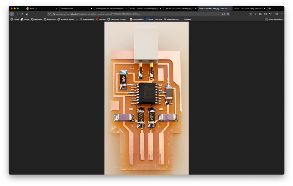
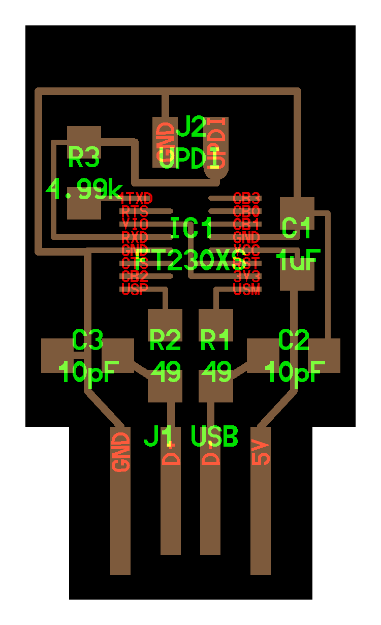
For the individual assignment, I made the UPDI USB. This is how the example from Neil looks like:
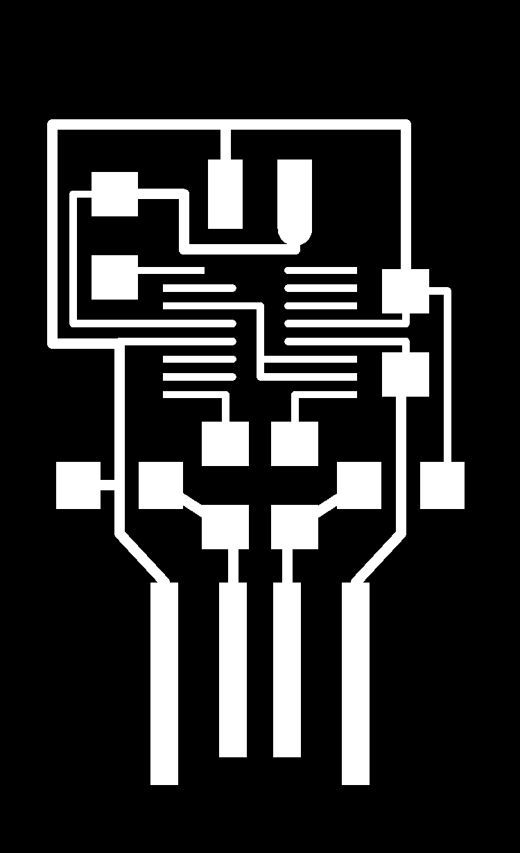
Interior:

Traces:
Preparing the file in mods
First upload the traces file in mods and check if the DPI is 1000.
Select mill traces.
In the mill raster 2D window, set the tool diameter : 0.4 the cut depth : 0.003 inch and max depth : 0.003 inch.
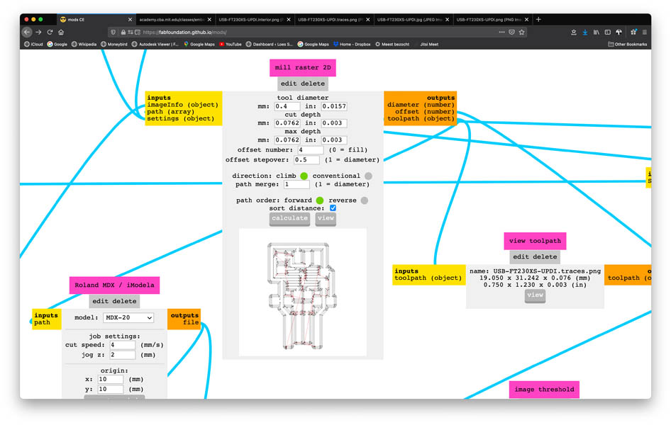
Click view on the view toolpath window.
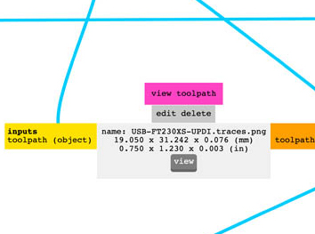
This will open the viewer. Confirm if this is the correct result.
In mods, move to the Roland MDX / iModela window. Set cut speed : 1.

And position the mill correctly by changing the origin.
In the mill raster 2D window hit calculate.
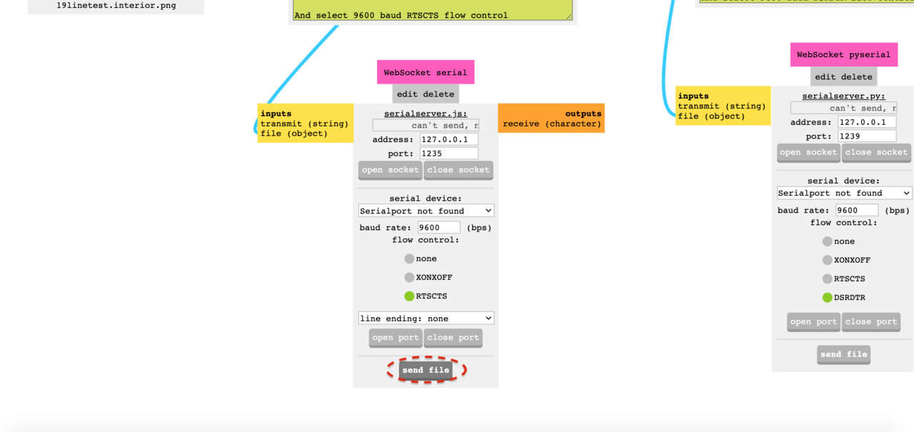
In the WebSocket serial window, click send file. Now the milling process will start. Note: this screenshot was taken on a different computer, because it would create a nicer image than a photograph from the computer screen. Therefore, here it shows the message ‘serialport not found’. This message is correct on the computer that’s connected to the machine.
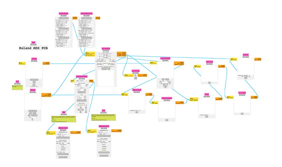
Here is an overview of how the mods program converts a png to a machineable language, such as gcode.
Now the milling process of the traces starts. This is captured in the documentation below.
If that’s ready, we move on to setting up the interior file in mods. Click mill outline (1/32).
Change the tool diameter : 0.8 mm the cut depth : 0.6096 mm and max depth : 1.6. Also, offset number : 1.
Open view toolpath using view.
And set cut speed : 4.
Then you can hit calculate in the mill raster 2D window and send file in the WebSocket serial window, to start the milling job.
Milling process
Make sure to not lower the mill too far (like I did the first time), because then you won’t be able to take out the end mill!
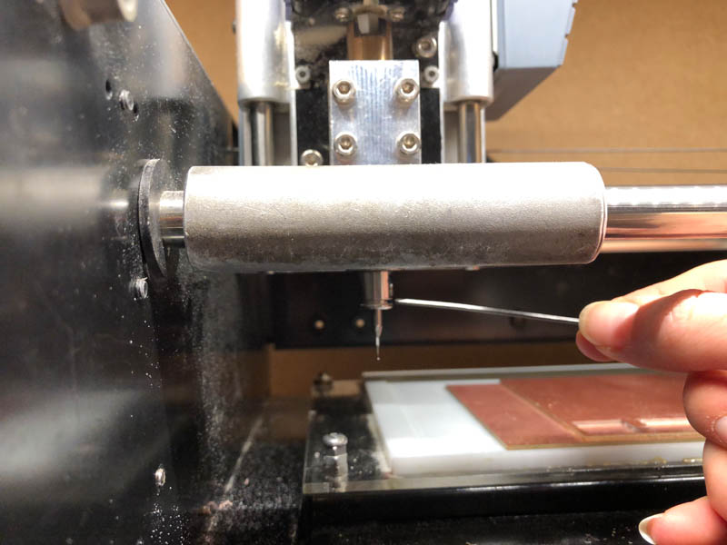
Positioning on the board.
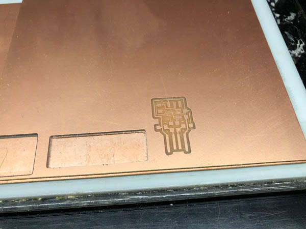
Result after milling.
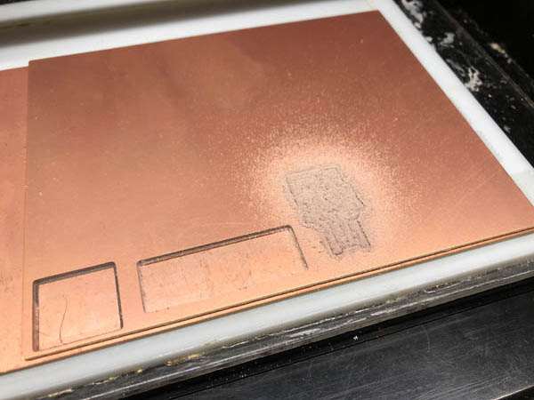
Vacuum cleaning the traces.
Intermediate result.
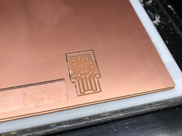
Milling the outline.

Result of both the traces and outline.
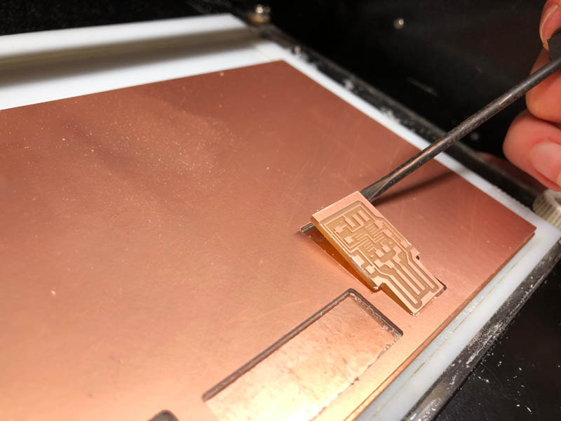
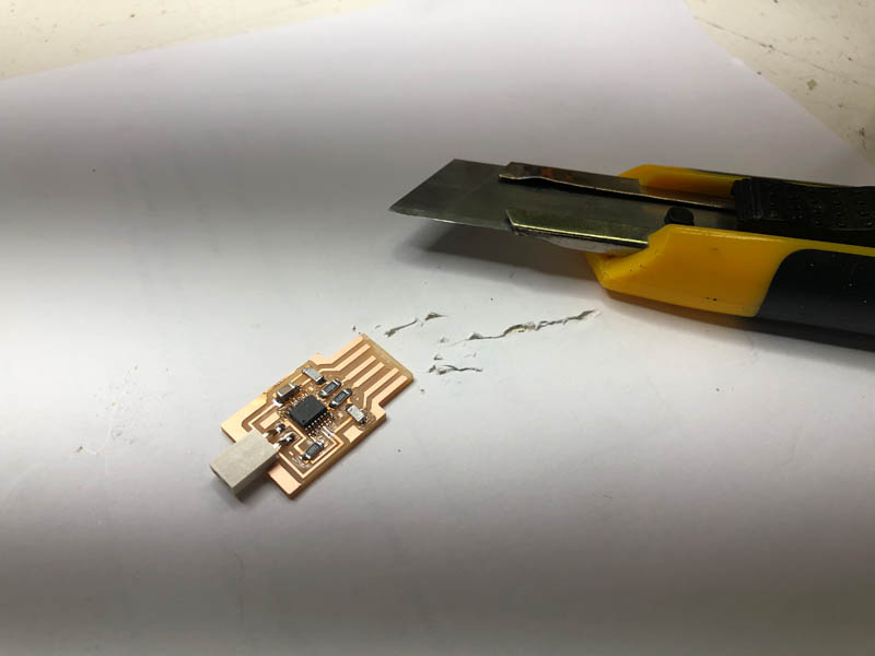
Carefully remove the design.
Make sure to clean the board with soap. This removes the grease.
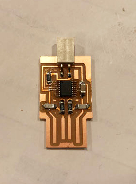
Result!
Soldering
To demonstrate the process of soldering, our local instructor Henk soldered the first part.
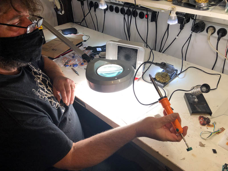
The result.
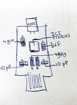
Next, I made a drawing of the components based on the UPDI schematic provided.
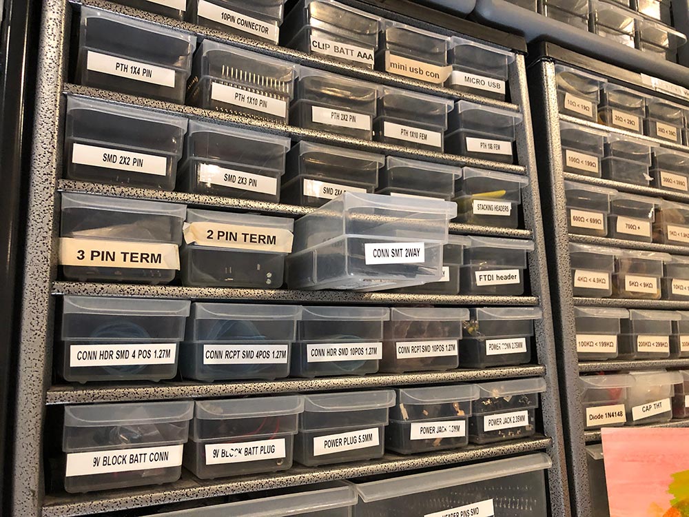
And collected all parts. Pro tip: make sure to open one drawer at the time, because otherwise you might mix up the components.
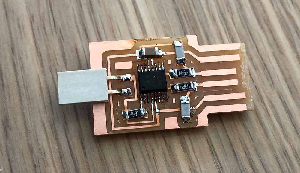
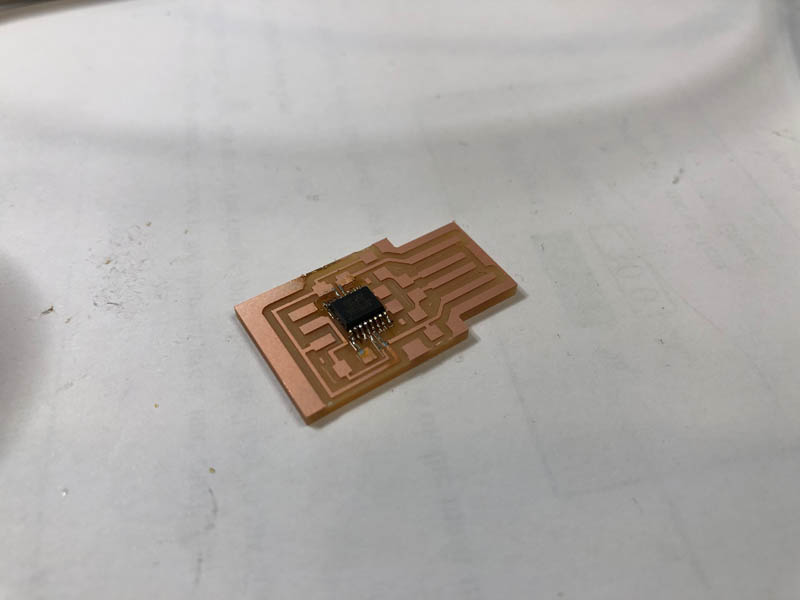
Then I soldered everything.
The board is now ready for testing its functionality.
Desoldering
If you made a mistake with soldering, you can remove solder. There are three ways to desolder, as shown on this wiki:
- Desoldering pump
- Desoldering braid
- Desoldering station
I tried the desoldering braid once. At Waag, we have a desoldering pump and station. For this assignment I tried the pump, but this was a little too intense for me. For now, I prefer the braid.
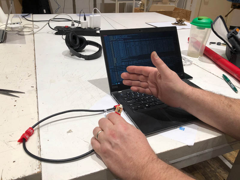
Testing
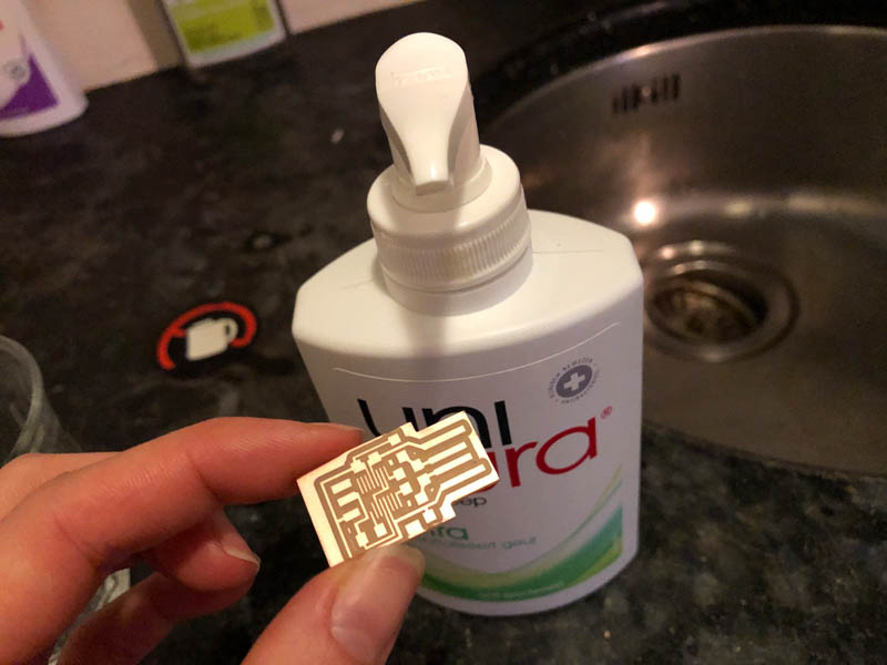
Before we can test if the UPDI works, we remove the copper at the ends with a Stanley knife. Otherwise it will make contact and that’s not what we want.
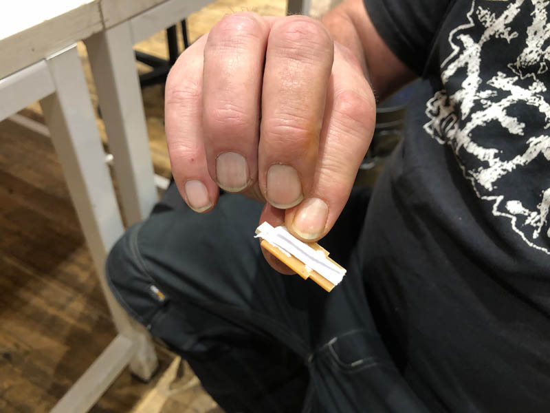
Add a piece of paper to the back, to make sure the UPDI makes contact with the cable.
Insert the UPDI in the cable.
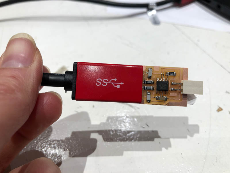
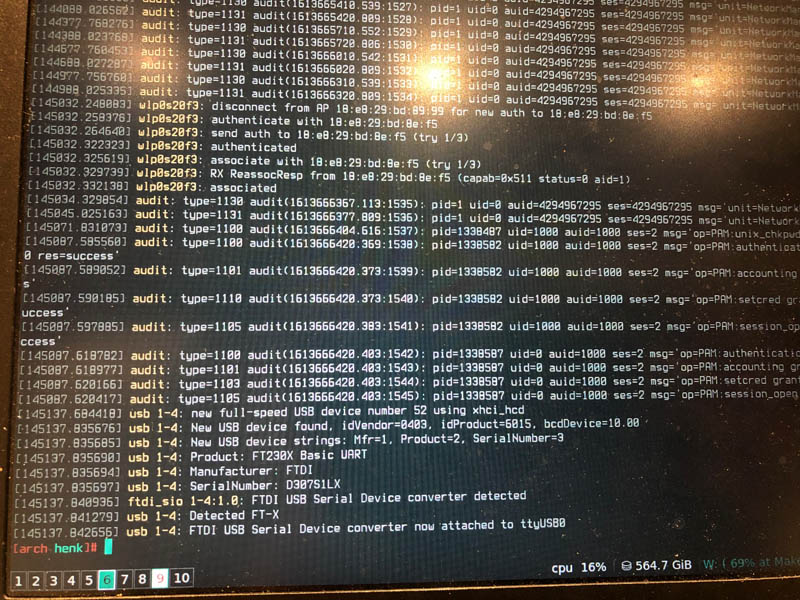
Connect to the computer and see if it recognizes the UPDI.
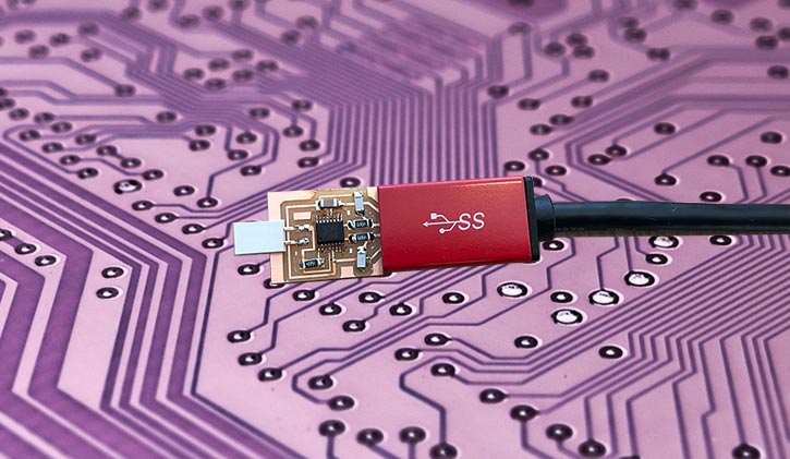
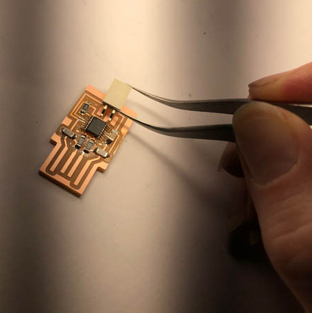
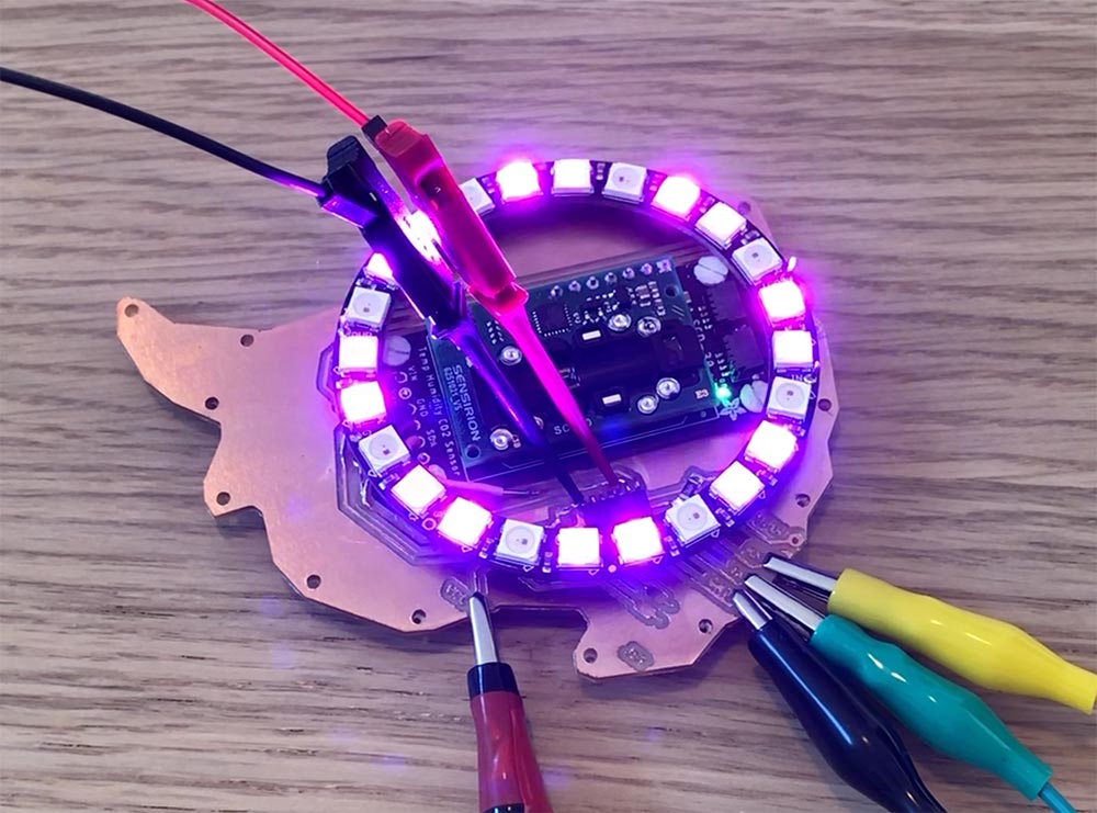
Hero shot!
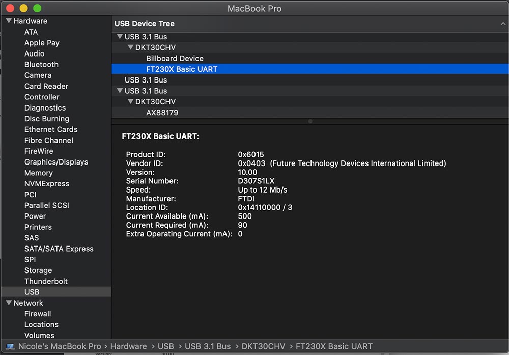
Testing on mac
To view the USB on mac, click on the Apple logo in your navigation bar (top left corner) and go to About this Mac. This opens a window. Click System Report. This opens another window, that shows your hardware. Go to the USB tab and check if your device shows up here. If it does, you’ve succeeded.
Downloads
Notes from regional meeting Europe
Another program to design PCB’s in, instead of mods is Flatcam.
Quentin Bolsee recommends to always use a vertical pin. A two-pin connector is fragile and if it’s soldered on the side it can break off easily.
Recommendation: Magnifying app on mobile phone.
Explore more like this
Week 17 Invention, Intellectual Property and Business Models
After acing through the technical assignments of Fab Academy, the last two weeks have a lighter load so we can focus on the final project. But this does not mean...
Week 16 Applications and Implications
Propose a final project masterpiece that integrates the range of units covered, answering: