Week 7 Computer-Controlled Machining
This week, we learn to work with the largest Fab Lab machine, the CNC.
Summary
The goal of this week is to get used to the CNC machine and its workflow.
“This week, the focus is not on creating a sophisticated design, but I want you to get to know the CNC machine and master its workflow. I want you to document everything.” - Henk
Assignments
Group assignment:
- Test runout, alignment, speeds, feeds, and toolpaths for your machine
- Document your work (in a group or individually)
Individual project:
- Make (design+mill+assemble) something big
Learning outcomes:
- Demonstrate 2D design development for CNC production
- Describe workflows for CNC production
Deliverables:
- Linked to the group assignment page
- Documented how you designed your object (something big)
- Documented how you made your CAM-toolpath
- Documented how you made something BIG (setting up the machine, using fixings, testing joints, adjusting feeds and speeds, depth of cut etc.)
- Described problems and how you fixed them
- Included your design files and ‘hero shot’ photos of final object
This week’s results
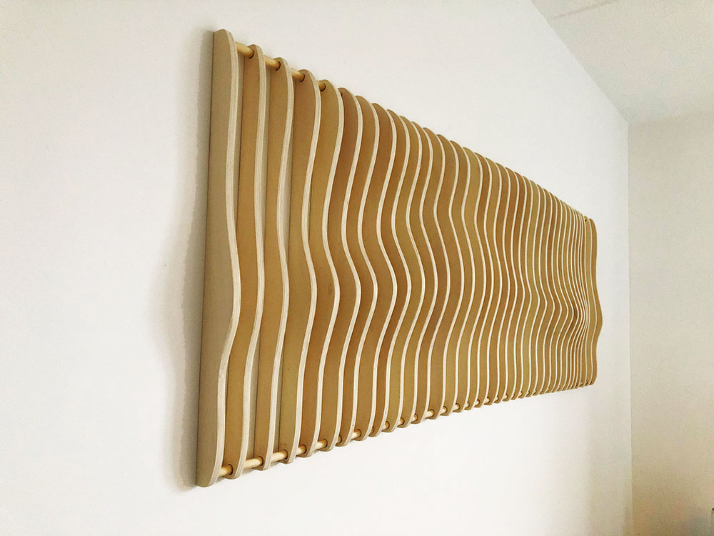
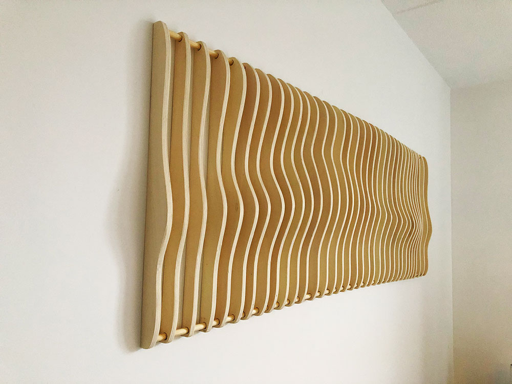
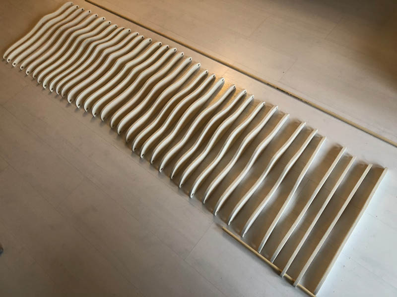
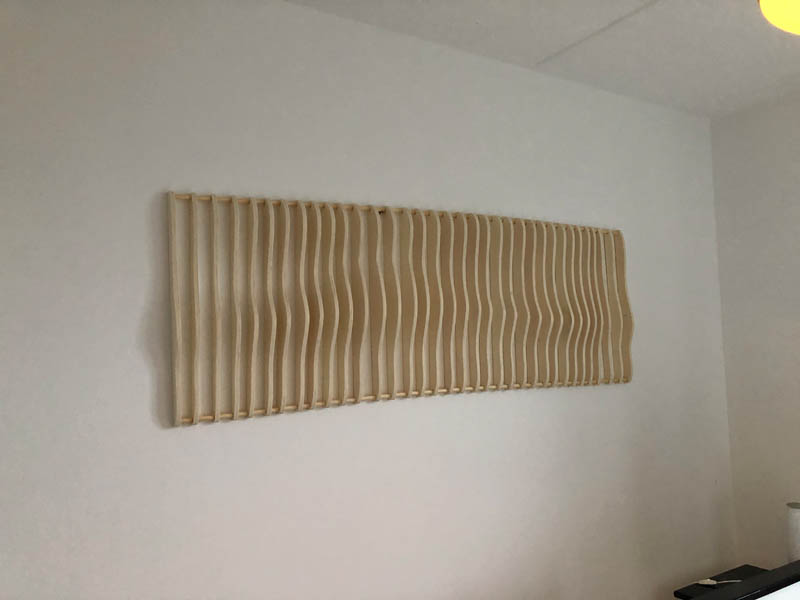
I made a curved artwork, inspired on waves.
Home lab CNC machine building progress
Along the weekly assignments, I’m also building out my home lab. To make the CNC3-3018Pro ready for usage, I ordered the following items based on Henk’s list of recommendations:
- CNC touch plate from Amazon
- Collets SainSmart Genmitsu from Amazon
- End-mill HRC-60 0.4 mm from AliExpress (I’m not a fan of this vendor)
- Sacrificial layer / copper plate
- Bed: acrylic layer for protection
- Double-sided tape
Hopefully they will arrive soon!
ShopBot large CNC
In this section, the procedure of file preparation and operation of the CNC will be written as a list. In the individual assignment, photos of the workflow are added.
Introducing: Sjonnie de ShopBot!
Safety Precautions
Attach wood to sacrificial layer with screws, make sure not to touch the screws with the spindle.
Make sure the emergency exits are freely accessible.
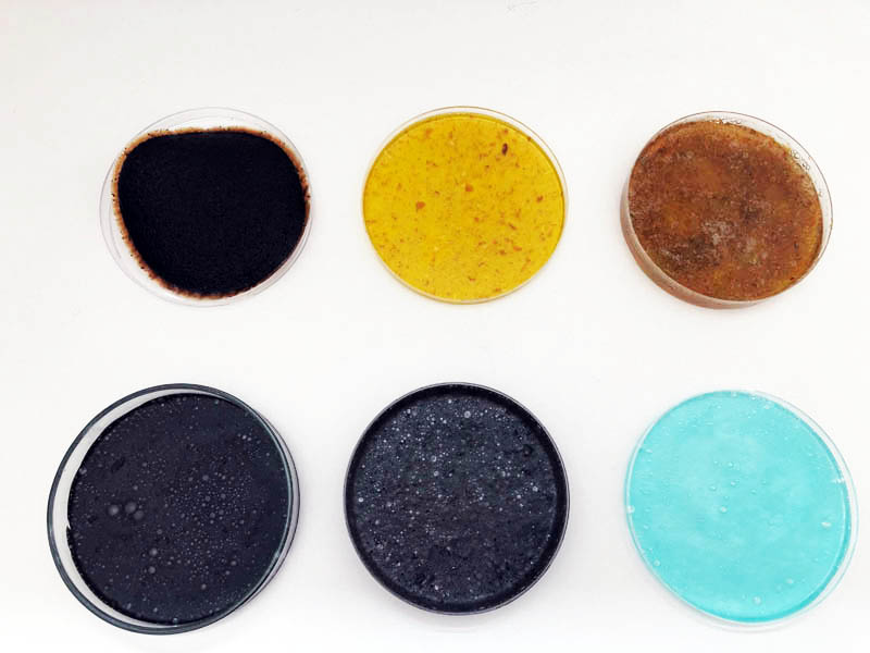
Choose milling bits
An important parameter for your milling result is the milling bit.
- 2-flute (black one) - end-nose
- 1-flute (silver one, larger)
- 4-flute (shiny) - ball-nose
For the group- and individual assignment, we work with a 2-flute nose-end.
! It is important to know how old the bit is. Press-fit pieces won’t fit if the milling bit is 4.7 mm instead of 5 mm. Parts will be made too small.
This can be mitigated with the Offset setting of the mill bit. The right offset is -0.3 mm. In Vcarve there is an option in the toolpath tool to set this for the right outlines and pockets.
Pass Depth (P.D.) = 1/2 of diameter of bit. With our 5 mm bit, this is 2.5 mm. Feed Rate (F.R.) = speed of rotation ?? / speed of moving along paths. Plunge Rate = speed of going into the wood (depth)
Prepare the bed
Before you start, prepare the machine bed.
- Choose a piece of wood and note down its dimensions, e.g. 18 mm thickness.
- Clean the bed from wood chips and other stuff. Also clean the area around the machine. Make sure you can’t tip over chairs and other stuff.
- Check how flat the sacrificial layer is.
- If needed, if there are any ‘volcanoes’, use sanding paper to make it flatter.
- Vacuum clean the bed with Kärdner and also the board.
- Place the board on the bed, make sure it touches the xy corner.
Create toolpaths with VCarve Pro
This procedure is for an 18 mm plywood board.
Settings for the board:
- Open VCarve Pro. Click
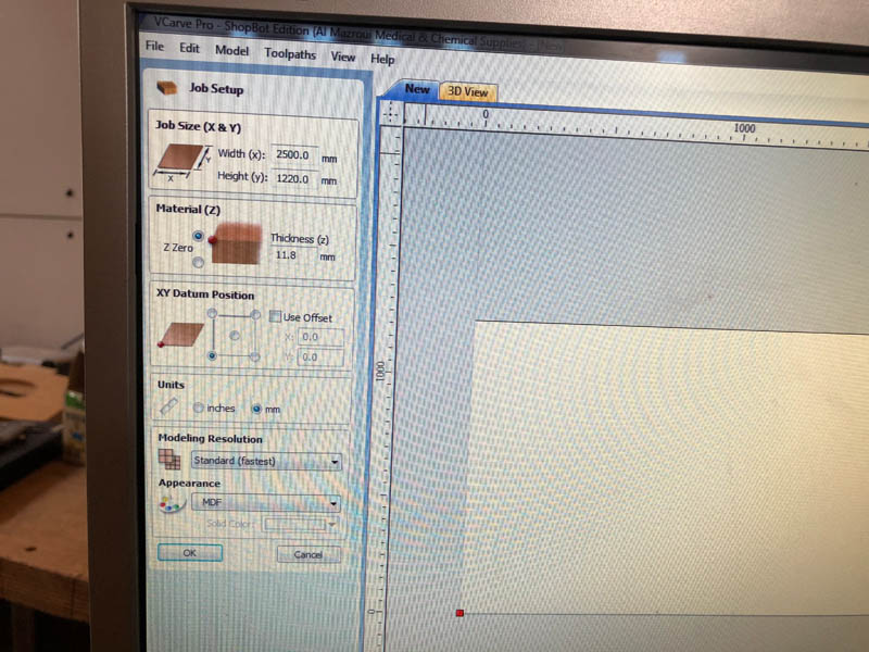
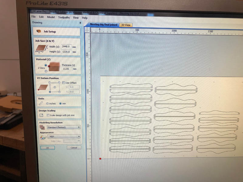
Create New Fileto start a new project. - The Job Setup Screen will appear. It asks for the material.
- Place the board on the milling bed.
- Measure the length of the board in x-axis direction with a roller tape, and enter this value in the software. This doesn’t have to be very precise, because your design will fit in it.
- Repeat the process for the length of the y-axis.
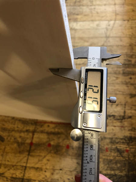
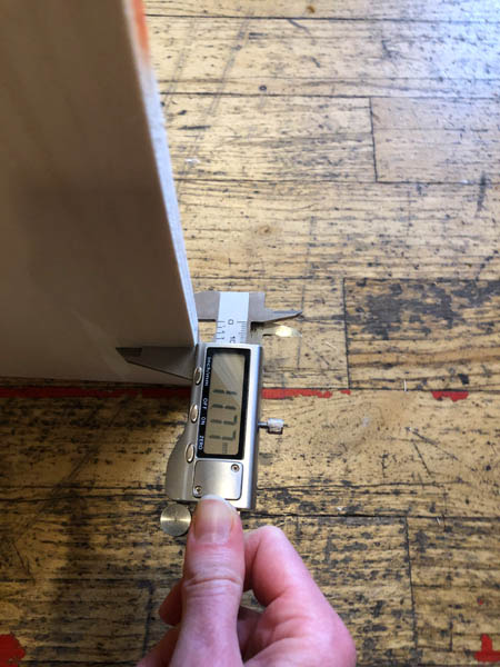
- For defining the z-axis, measure the thickness of the board with a (digital) caliber. Do this at multiple spots across the edges of the board. For example, if you have an 18 mm plywood board, it’s never exactly 18 mm! Of all measurements, take the average or most common value. We measured 17.9 mm. Beware: it’s easier to take out 1 mm from your design than to replace the sacrificial layer! You can better set it on the lower side.
- Position the origin with the red dot. Set the origin of the board with
Position XY. - Modeling = standard
- Appearance = “marble 2 / or plywood” This setting doesn’t really matter.
- Z zero = top of material.
- Click ok. Second screen.
- You can now import a file or draw something.
Toolpath settings of the screws:
- Import design file (EPS).
- If needed, rotate and move the design so it fits on the board. Keep enough space on the sides for the screws.
- Draw a few small circles around the design, these are makers for screws that attach the board to the sacrificial layer. These are holes of 5 mm or more (drill bit is 5 mm).
- In the software, select all screw markers you want to drill. This will be the first toolpath.
- On the right side, select
Toolpath. - Click
Drilling toolpath. - Settings for the screws are:
start depth = 0andcut depth = 12 mm(not all the way through the wood). - Select the ‘End Mill 2 flute fabacademy` tool. This will pre-load all settings of our 5 mm bit.
- Peck drilling setting is never used by Henk.
- In the menu: uncheck all: dwell at bottom, value and 3D view.
- Hit
Calculate. - A new screen with auto review will open. Preview the toolpath to make sure it’s going well.
Create fillets:
- Before creating toolpaths for the design, we add fillets in all internal corners. They make it easier lift the part from the board. On the main menu, select
Create fillets. - You can choose the type of fillet: dogbone or T-bone or …
- Manually add them to the design.
- If you want to change the position, select … and move it.
- If you add more fillets later in the design process, make sure to
calculateagain.
Pocket toolpaths:
- We continue with creating toolpaths for pockets. Pockets are elements in your design that you want to mill out partly. Select the circle that becomes a pocket.
- Select the
pocket toolpathfunction. - In settings, set the
cut depthto 7.5 mm andpass depthto 2 mm. This generates 3 passes. - Clear pocket:
offsetstarts in middle, set toraster. - Hit calculate.
- Preview the toolpath.
Square pocket for pressfit toolpaths:
- This is where the part will land into. Select the square and open
pocket toolpath. - Set
cut depthto 9 mm. - Select
raster. - Calculate.
- Preview.
Internal square pocket (all the way through) toolpath:
- Select the shape you want to cut all the way through and click
profile toolpath, this is the first icon. - Enter a
cut depthof 17.9 mm. This will create a path with 8 passes. - Select
inside/left. - Check
Add tabs to toolpath. Otherwise pieces will fly. This is to help keep the design in place during milling. - Enter
Lengthof 5 mm andtof 5 mm. CheckCreate 3D tabs. - Hit
Calculateand preview the toolpath.
Outside boundaries toolpath:
- Select all outside boundaries and click
profile toolpath. - Set the
cut depthto 17.9 mm. - Make
offsetof -0.3 mm - The black line is the center of the milling bit. Don’t know what this is: [9 outside profile]
- Select
use tabs(4x). Keep in mind the precision of the tabs. Never put it in the corner or in an internal structure. Then it’s impossible to take out. Clickeditto move, add or remove a tab. - Hit
Calculateand view the resulting toolpath.
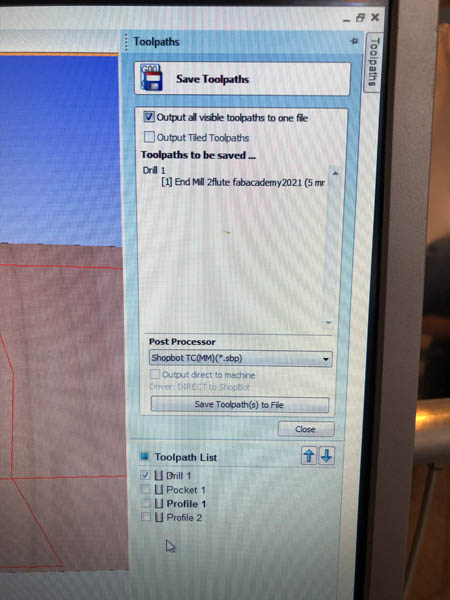
Exporting toolpaths:
- Select
Preview all toolpaths. Preview all of them. - Click
Save toolpaths. - Check
Output all visible toolpaths to one file. - First, save the drilling toolpath to one file. Only check this and uncheck the rest. Select
Export Asand choose the ShopBot.sbpfile. Name the folderscrewit. - Next, UNCHECK the toolpath with markers for screwing. This is really important because if the machine hits a screw, it creates sparks that can set the building on fire.
- Then check all toolpaths for the pockets and profiles of your design. Save it as an
.sbpfile.
In the Toolpaths Summary, preview total machining time.
- (Fix the board to the sacrificial layer.)
Send toolpath to machine with ShopBot
With ShopBot version 3 software you can send the gcode to the machine.
Design file: export as pdf, dwg.
Phase 1: Setting job home
- Open software, it will complain that it can’t communicate with the machine. That’s correct because it’s still turned off.
- Hit
K. That’s the most important shortcut for opening the yellow screen. You can operate the axes of the machine with the following keys on the keyboard:Arrow UpandArrow Downare for the Y-axis, arrowsLeftandRightare X-axis,upanddownkeys are for the Z-axis. - Take the machine to its x and y home. This is done automatically by the software.
- With the keys, navigate tot the job’s home.
- The
Zero to XYis the most important button. Click this if you found the right position.
Phase 2: Attach milling bit
- Choose a milling bit
- Unscrew shaft from machine
- Turn shaft and click in the bullet first
- Add the milling bit, push it in about 2 cm. (rib on shaft is approximately 2 cm)
- With a measuring tape, measure how far the bit come out on the other side. It needs to stick out 3-4 mm more than the thickness of the chosen board to make sure the bit comes all the way through. E.g. for an 18 mm board, the bit should stick out 21-22 mm.
- Now you can gently attach the mill to the machine, do this by hand.
- Lower the skirt (used for vacuum cleaning) with the screw on the back
- With two tools, fasten the milling bit tight. Make sure you can still loosen it afterwards.
- Push skirt back up and fasten.
Settings:
- Back on the computer: type
Kto open the keypad. Navigate to the origin.
Design
For this assignment I created an artwork with a wave pattern, inspired on ripples on water. In the future, I’m planning to design a tiny house with a wall paneling system that continues across the ceiling. This method is the first spiral to test the parameters of the machine. This is the Grasshopper tutorial I consulted.
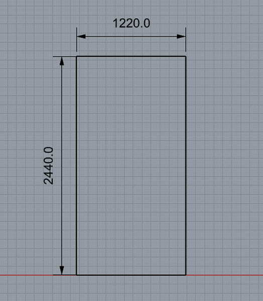
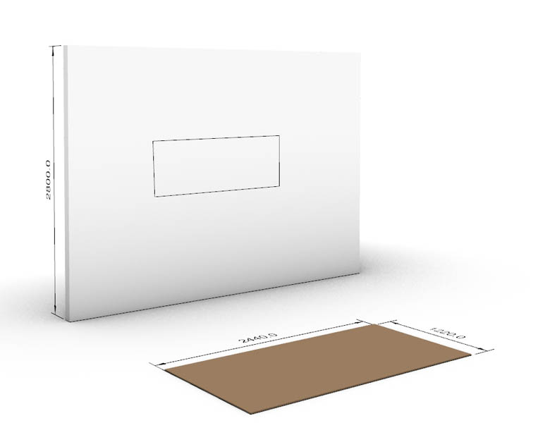
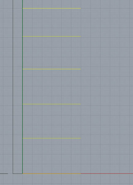
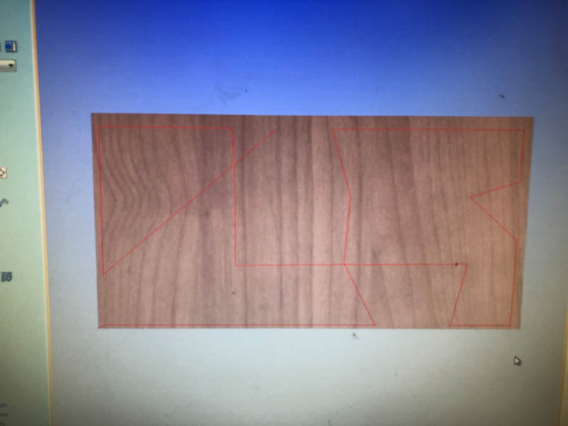
Start with drawing the dimensions of the plywood board, to get an idea of how big the object will become. This also helps for keeping in mind the limited amount of space.
On the Y-axis, design the wall, and the width of the artwork.
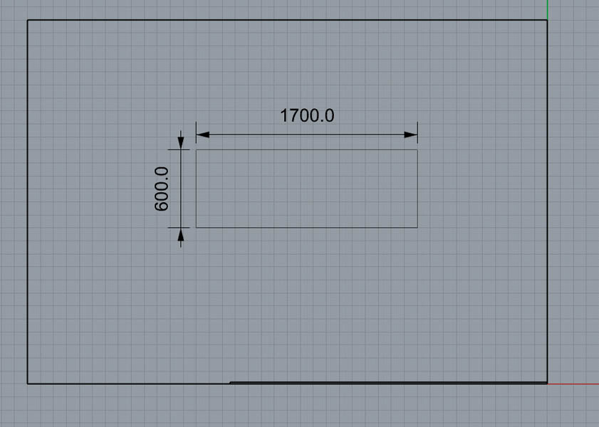
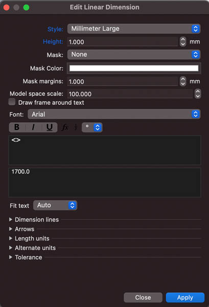
As an engineer who’s used to AutoCad, I find Rhino less intuitive in terms of dimensions. That’s why I always add them during the design process. Type dim to add a dimension. In the menu that pops up, set the height to 1.00.
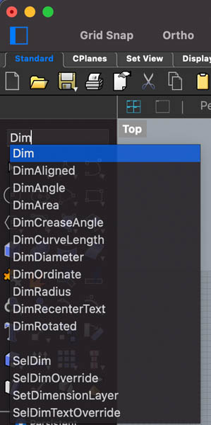
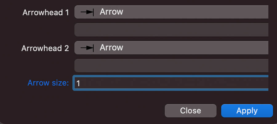
Scroll down, and set the arrows to 1.00.
This first step is not really needed for the design, but it creates a good reference point.
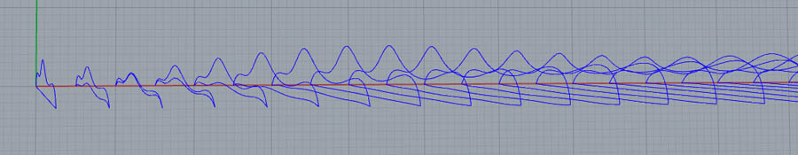
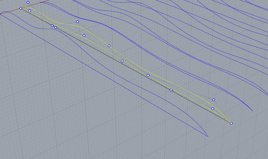
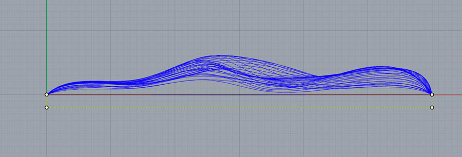
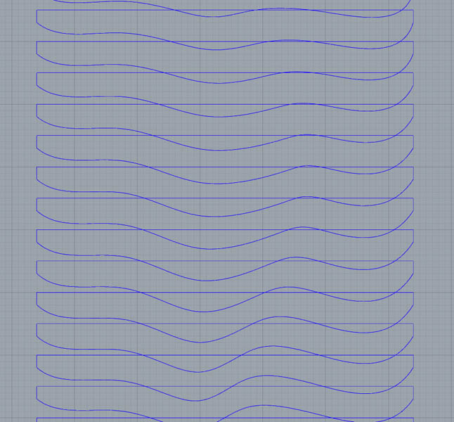
With Curve through points add a curve.
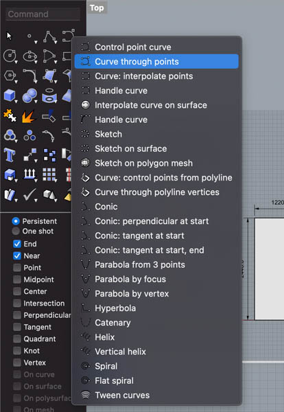
For example like this:
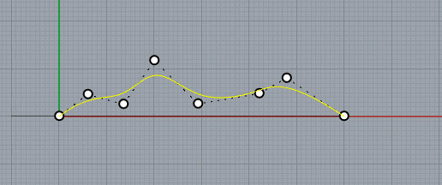
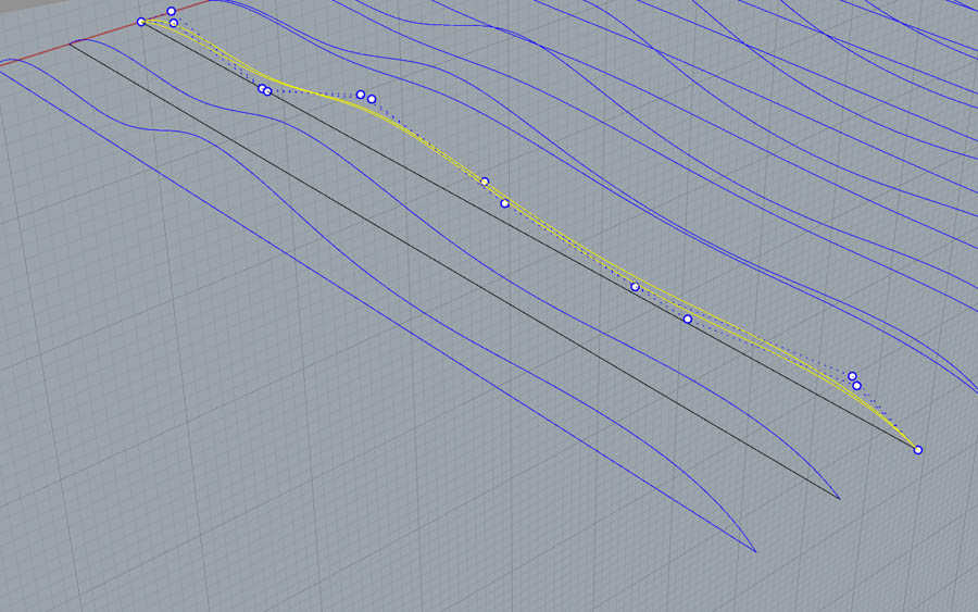
Click on the dots to adjust the curve.
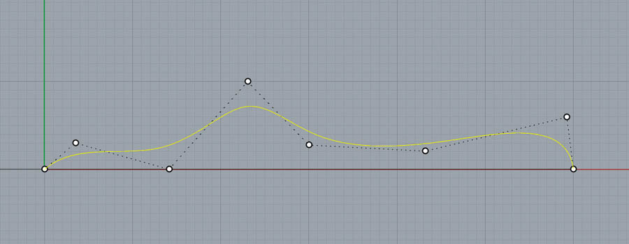
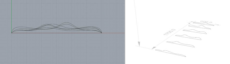
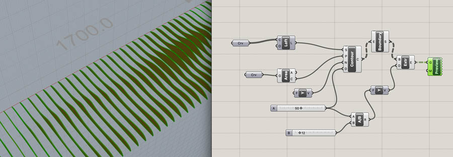
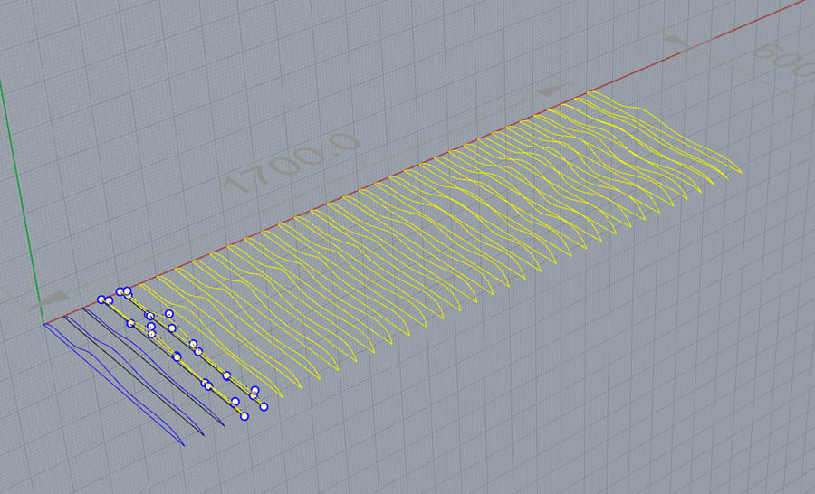
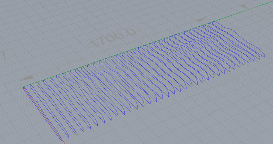
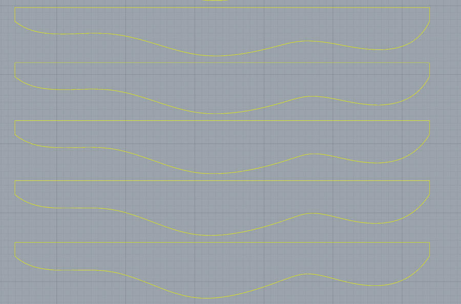
Copy the curve a couple of times and distribute evenly across the 1700 mm.
Change each individual curve a bit.
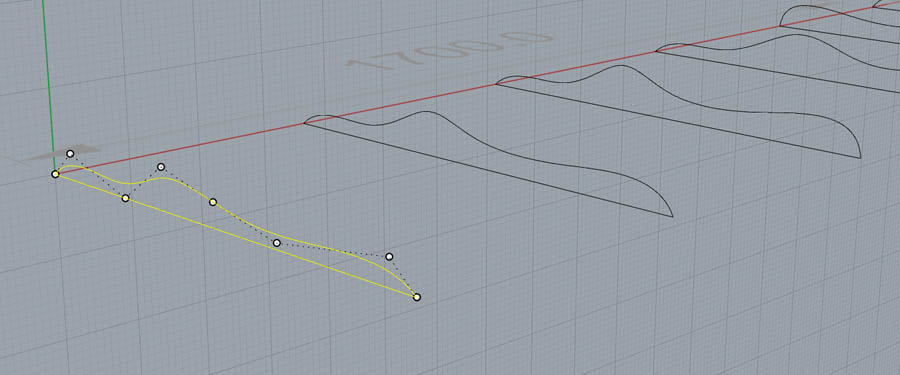
This creates a dynamic wave pattern.
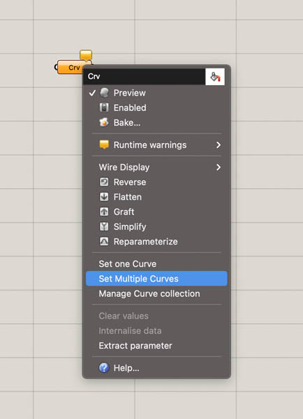
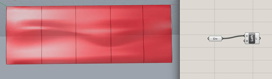
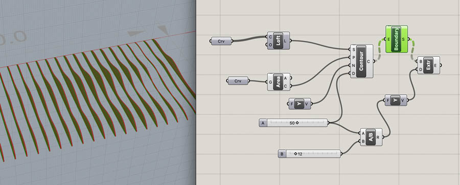
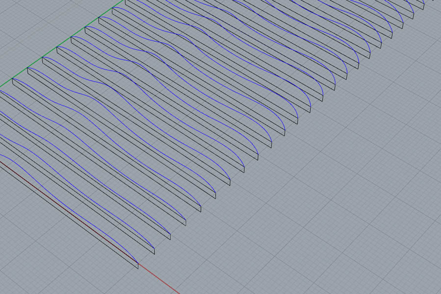
When you’re happy with the desingn, type Grasshopper to start with parametric design. Place a Curve component and right click Set Multiple Curves. In Rhino, select all curves.
Then add the Loft component. Check in Rhino if you’re happy with results. Otherwise change the points.
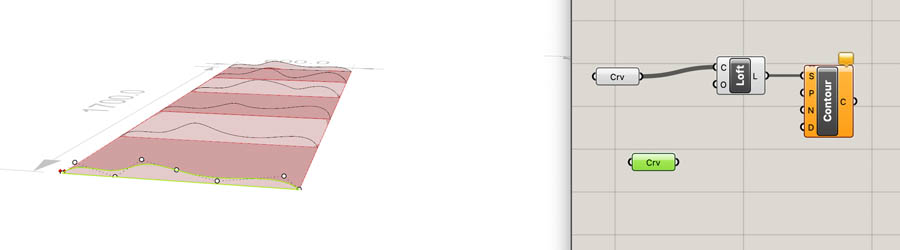
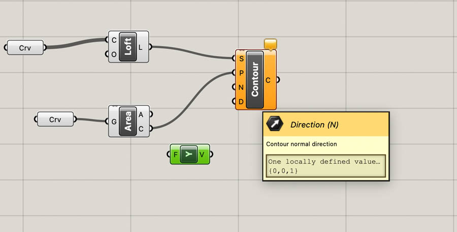
From the Intersect tab, under Mathematical, select Contour. Create a new curve and with Set One Curve select the first curve in Rhino.
Add Area, this creates a dot in the center.
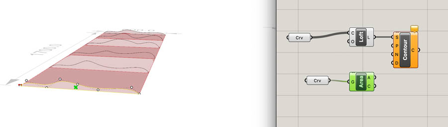
Connect area to the Contour.
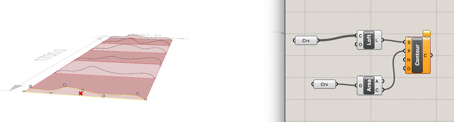
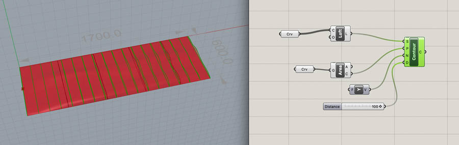
For the direction (N) we add a Unit Y.
And type 100 to get a number slider from 0 to 100. This is 10 cm distance in between the panels. We’ll adjust this later.
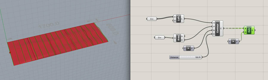
Add the Extrude component and another Unit Y.
Add a Division and connect A to the number slider. For B, create a new slider. The plywood board has a thickness of 12 mm.
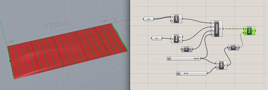
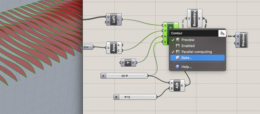
The ‘heart-to-heart’ size is 50 mm. Set the number slider to 50. Add Boundary Surfaces and place this in between Contour and B from Extrude. Disable preview from Loft and others.
Click Preview to show the resulting shapes.
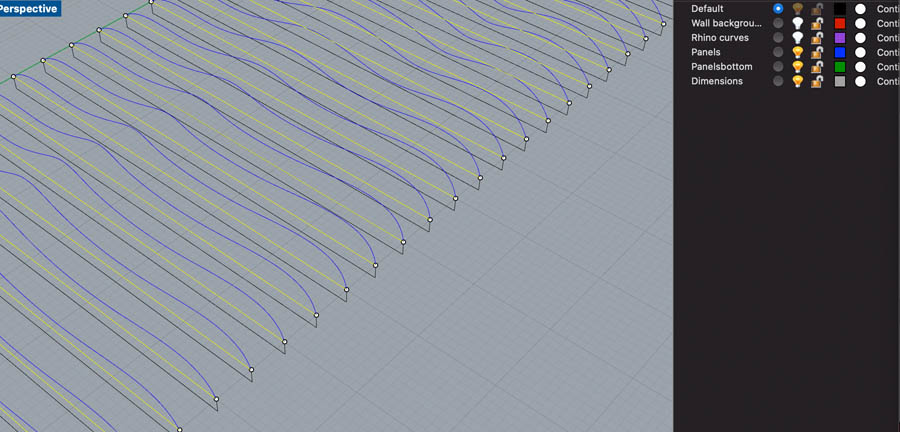
In Rhino, create a new layer, call it Panels. Bake the Contour in this layer.
The resulting shape of the bottom is not exactly what I intended. The tutorial doesn’t create a flat bottom.
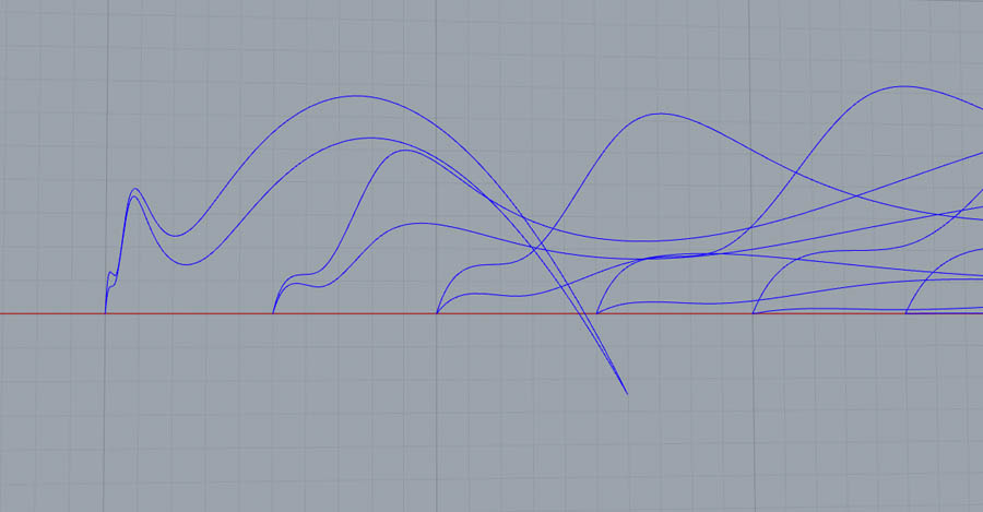
This is also the case at other lines.
In the Default layer, manually create lines underneath the shape. Use Line and draw from one side to the other.
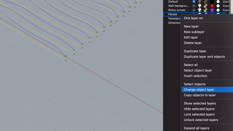
Click Explode to remove the lowest line. Keep the upper shape (selected).
Because I don’t want to take a risk of not having a flat surface, I explode everything and redraw the bottom line of each.
I noticed that there would not be enough space for the rods, so I added 2 cm below each shape.
Copy this to all curves.
Delete the flat line.
Change the object layer of the new bottom line to Panels.
If you’re ready, Join the shape and the base of each curve.
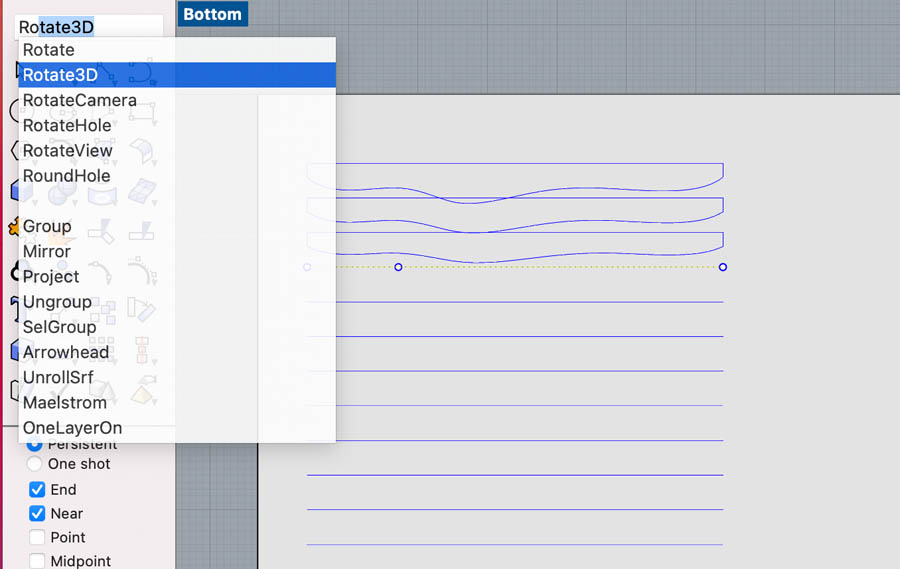
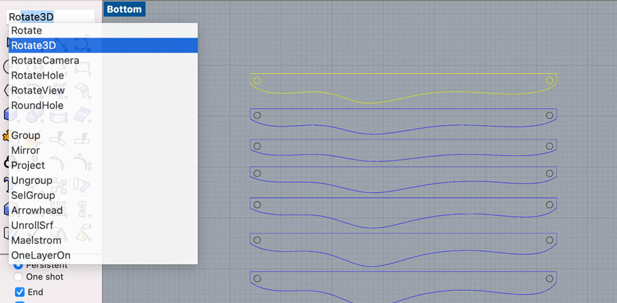
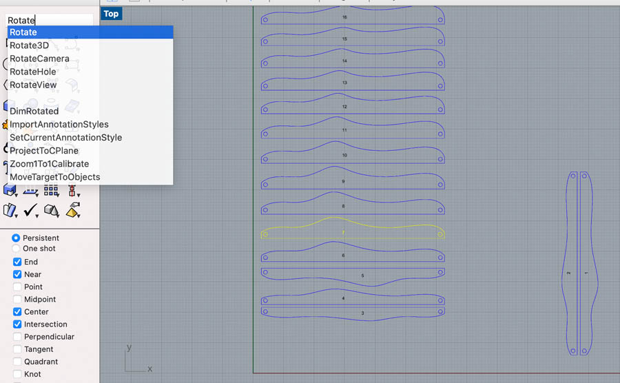
Now we’re going to lay them flat, in preparation for milling.
Type Rotate3D to do this. In my experience, rotation can be a bit tricky in Rhino. Make sure you select the right rotation axis.
Do this for all shapes. This is quite time consuming. I’m wondering if there is a possibility for a more automated process!
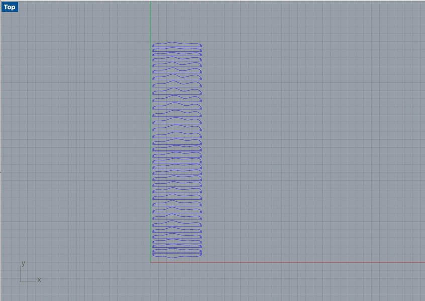
The shapes overlap. This is not what we want for milling.
A quick way to space the elements is with Distribute.
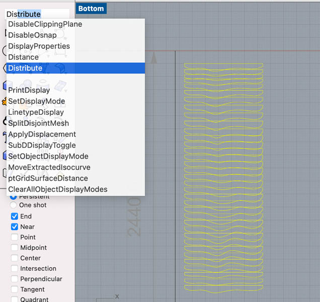
Set the gap to 10 mm.
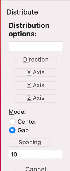
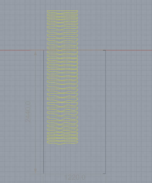
This will space out the panels nicely.
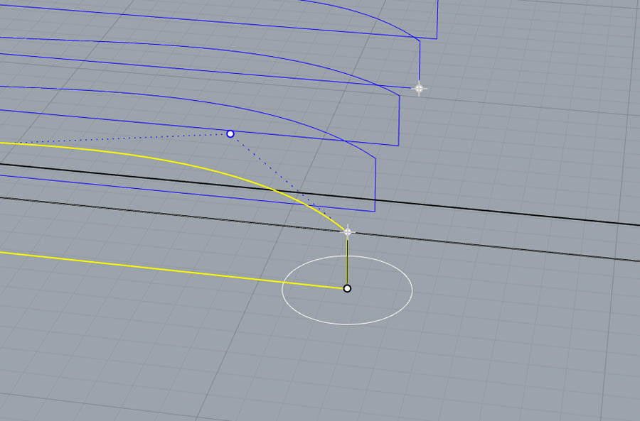
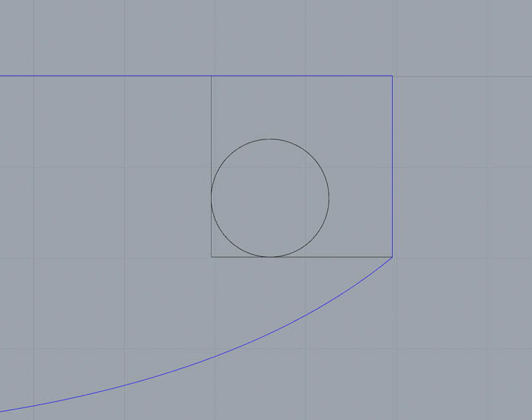
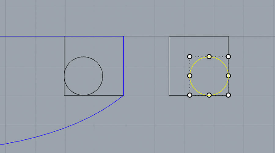
We’ll add a circle for the rod. It’s easy to draw this manually in 2D.
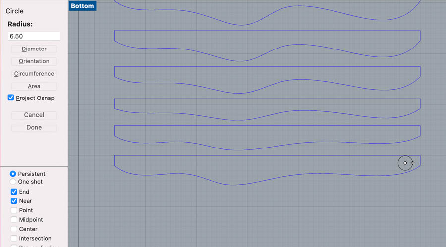
Make a reference box to position the circle at the desired coordinates.
Use Copy to duplicate this shape.
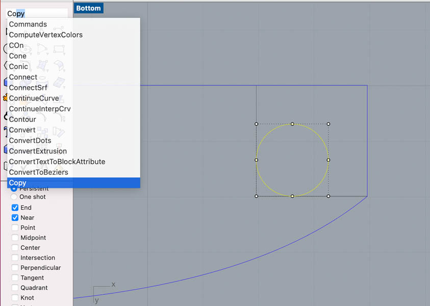
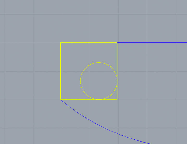
Add this to all shapes.
Copy the circle and the support shape, and mirror it.
Place it on the other side of the panel.
And copy this to the other side of the panel.
Select last shape and Rotate it. This is the end, so want to create a ‘cap’.
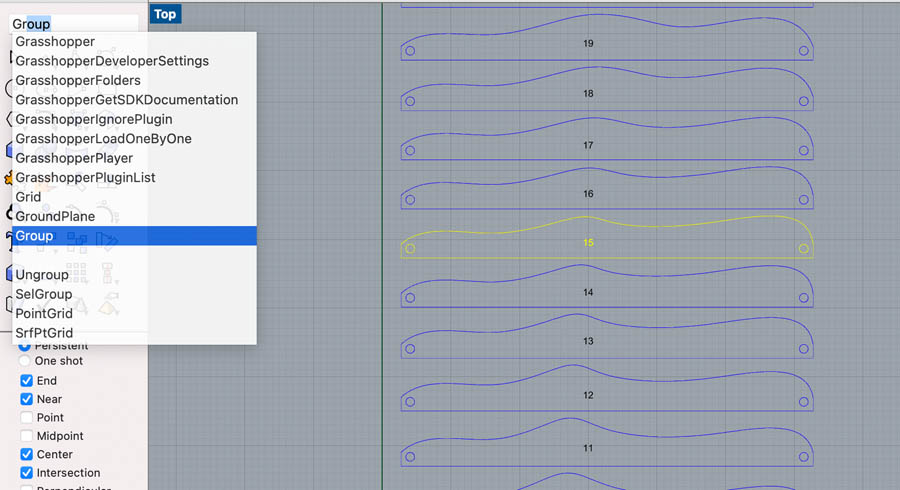
Next, group each element (panel and holes).
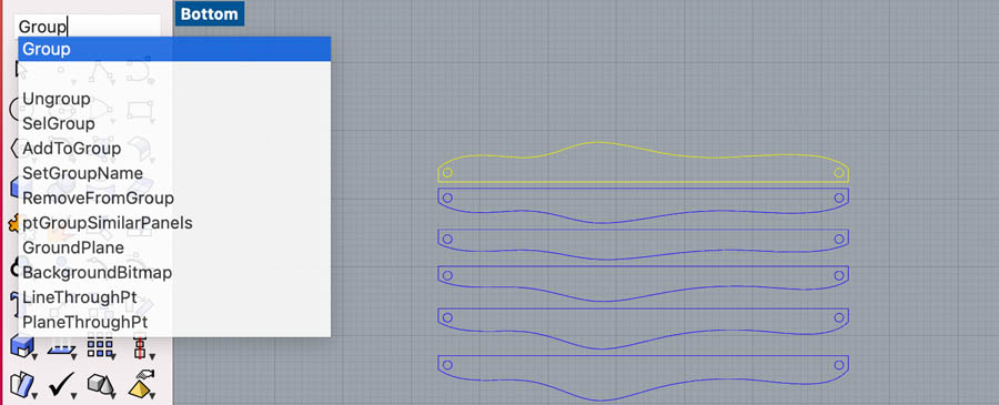
Do this for all shapes.
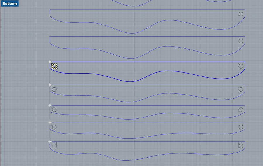
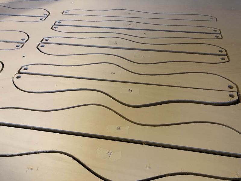
In another layer, add numbers.
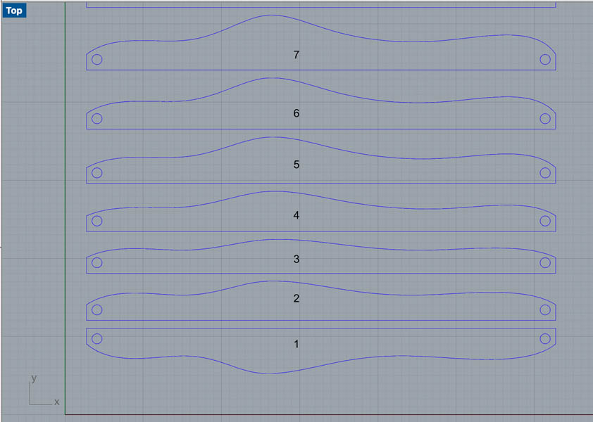
And group this again.
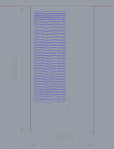
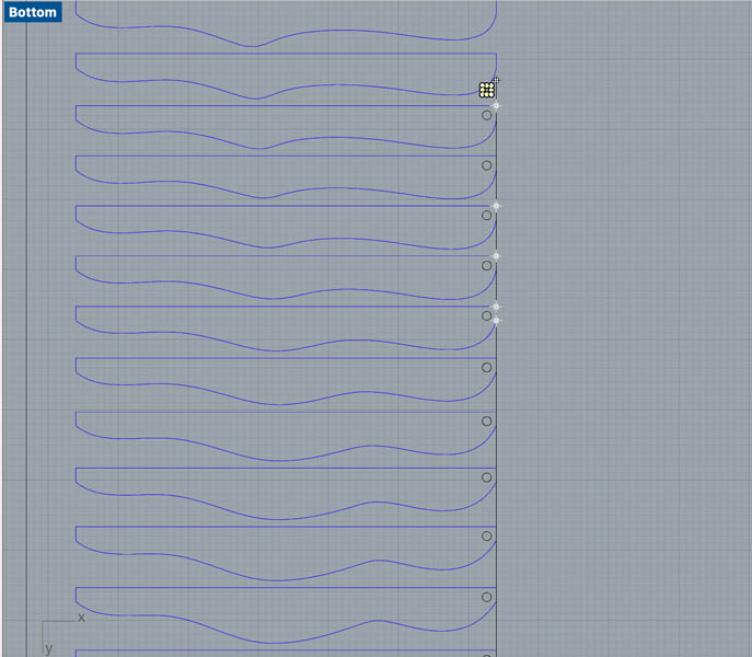
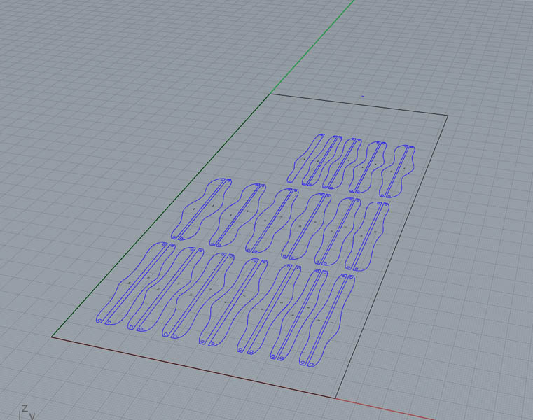
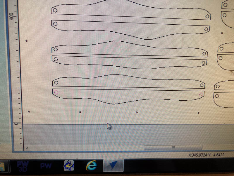
Now we’re going to lay out the panels on the board, and prepare the file for milling.
I’m trying to do this as efficient as possible.
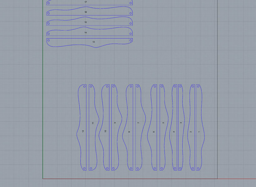
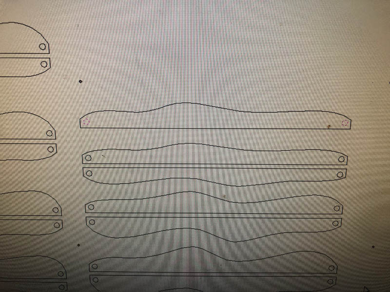
This is the resulting layout on the 1220 x 2440 mm plywood board.
Adding drillholes
For screwing the board to the sacrificial layer, create small drill holes. The drillbit of the CNC has a 5 mm radius. Place them approximately 300 mm apart. Also add a couple in between the design.
Exporting for VCarve.
From Rhino, export to DXF. Make sure to set the units to mm.
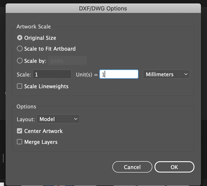
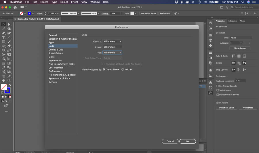
Open Illustrator, set all settings to mm. Import DXF, all settings to mm and scale 1:1.
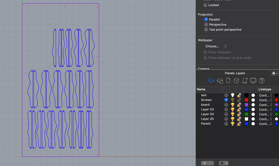
Change the artboard to 1220 x 2440 mm, make all layers visible, select everything and move the plywood board in the exact position of the artboard. Make the board and text layers invisible.
I noticed that Illustrator splits the object into two lines. This is not what we want.
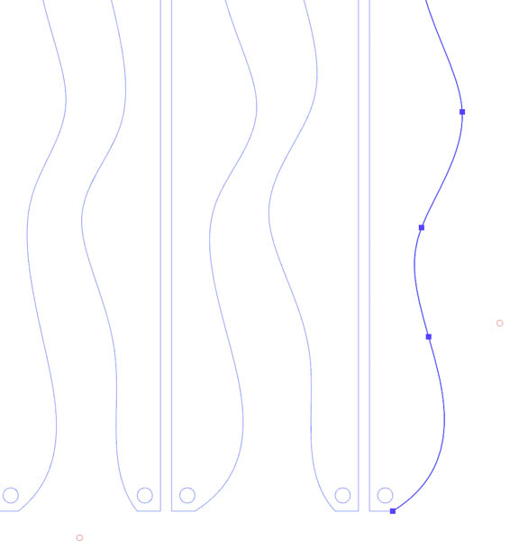
These lines need to be joined. Use the procedure below or the shortcut Command and J.
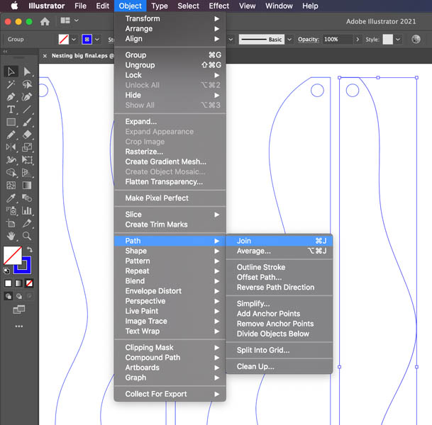
Export to SVG and save as EPS.
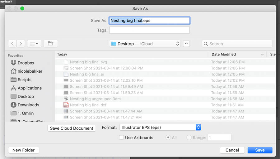
Now you’re ready to open the file in Vcarve Pro.
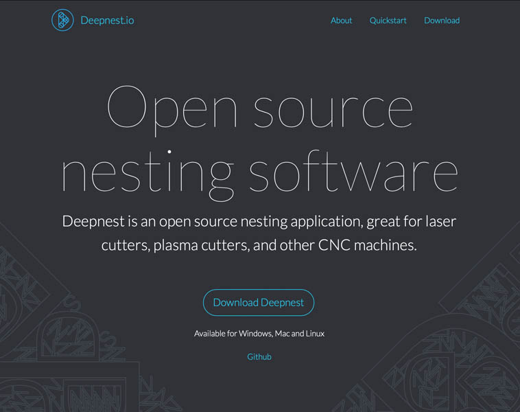
Deepnest.io
A method for nesting is the Deepnest app.
Open the SVG file.
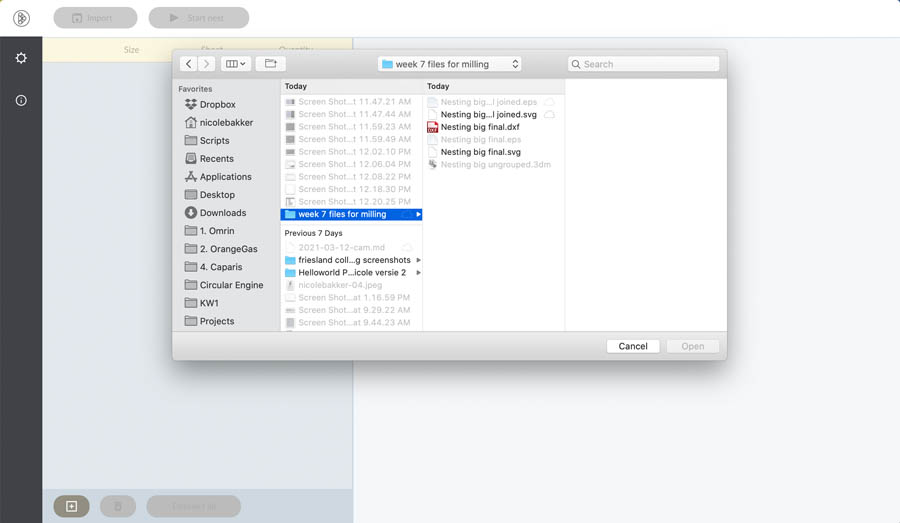
Check the position.
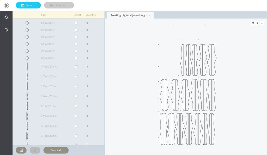
Start nesting.
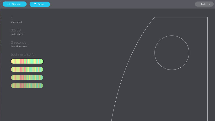
I’m not happy with the result, because it moves all drillholes in the panels.
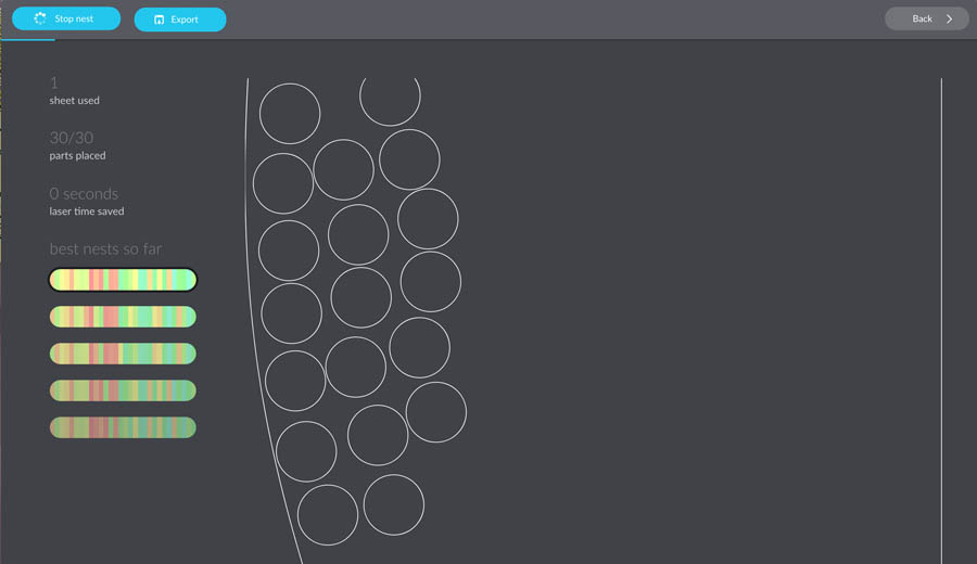
Later when I have more time, I’ll explore Deepnest further.
Milling process
The milling process consists of two parts: file preparation in VCarve Pro and sending gcode to the machine with ShopBot’s own software.
Vcarve Pro
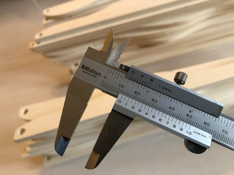
First, start with measuring the 12 mm board with a caliper. It’s never exactly 12 mm. Measure this at multiple points.
Enter the thickness of the material in VCarve.
Open your file.
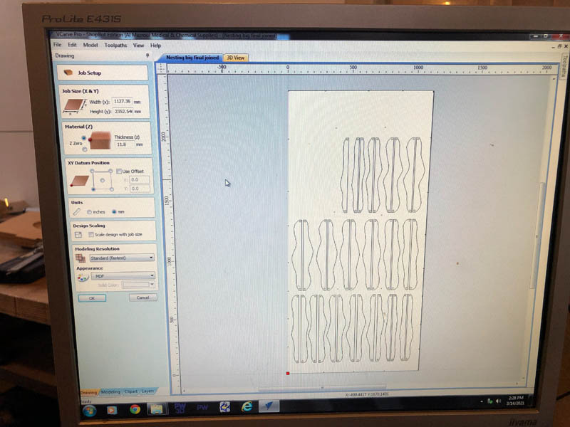
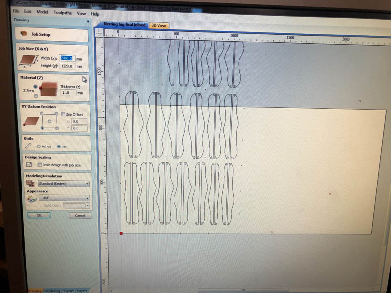
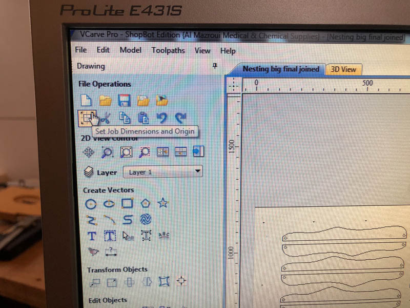
Set the right Job Size, make sure this corresponds with the machine bed dimensions.
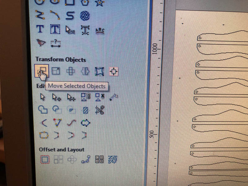
In the panel on the left you can find operations to transform objects.
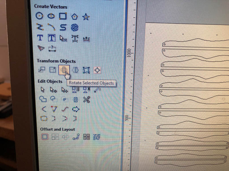
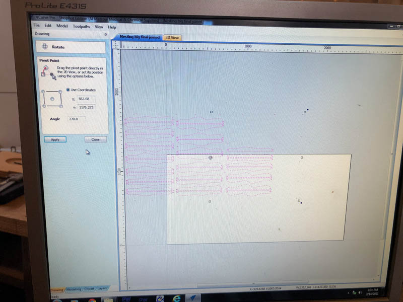
Use the Rotate tool to rotate the design.
With the Move tool you can move it in the right position.
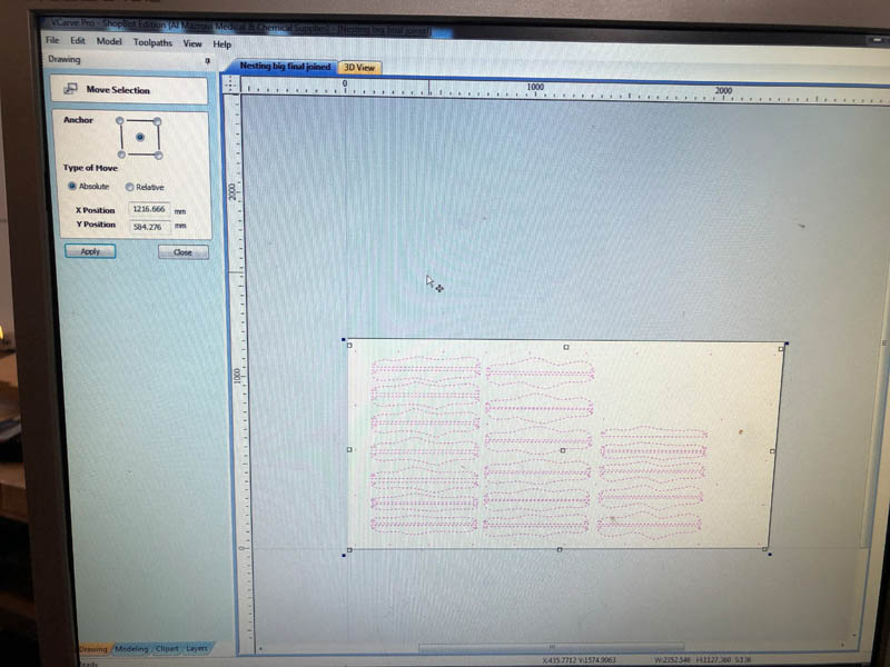
Delete the outline of the bed, drawn in Rhino. The red dot in the left corner is the machine home.
Set Job Dimensions and Origin to confirm this position.
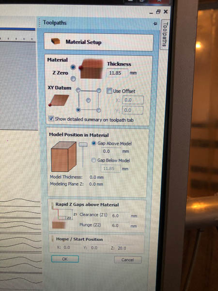
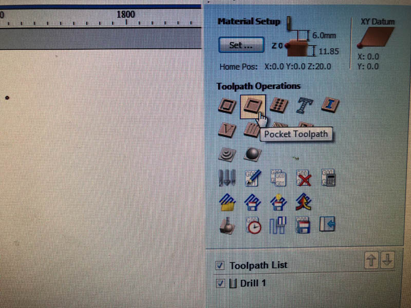
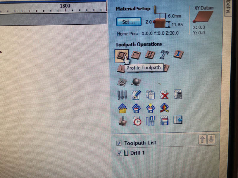
Increase Material Thickness to 11.85 mm.
Click Drilling Toolpath.
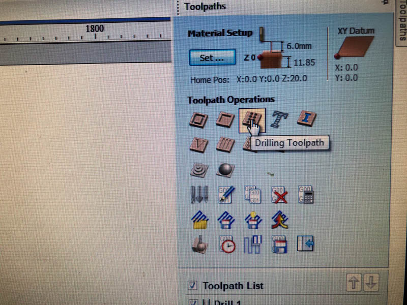
This will open the following panel. Set the Cut Depth to 9 mm.
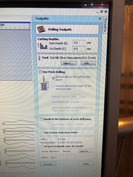
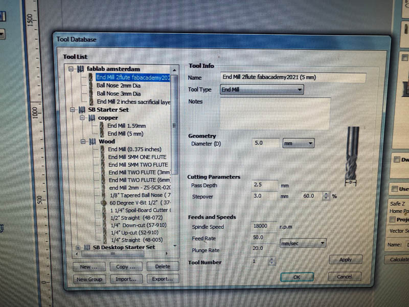
At Waag, the settings for the Tool are already included. We use a 5 mm 2-flute end-mill.
Click OK, and a preview of the toolpath for the screw holes will appear.
Next, select the four ends that will become pockets.
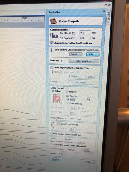
Open the Pocket Toolpath.
This will open a panel. Set the cut depth to 6 mm. Click Edit Passes.. to specify the pass depths.
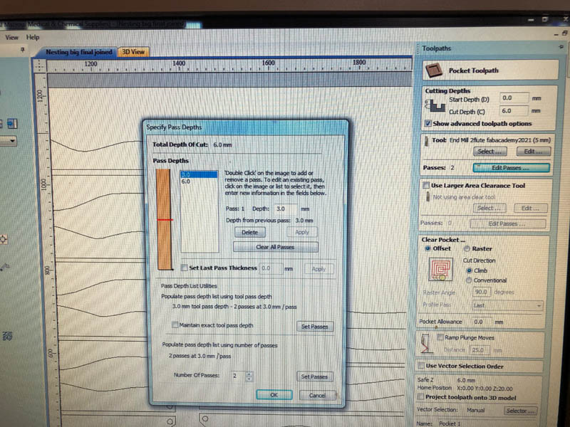
At the Edit Tool panel, set the pass depth to 2 mm.
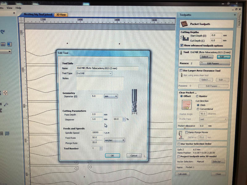
The machine will make the pocket in 3 passes.
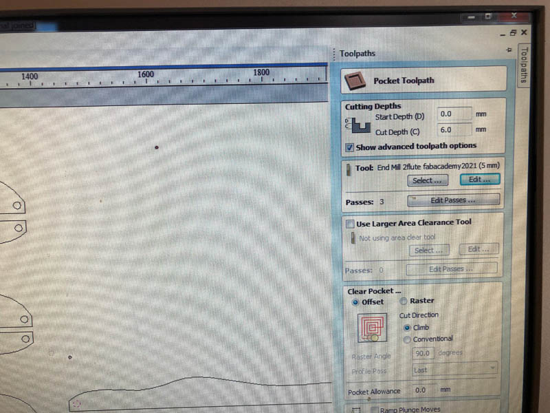
In Clear Pocket, select Offset and choose Climb for the Cut Direction. Click Calculate to generate the toolpath.
Next, select all circles that will be cut through.
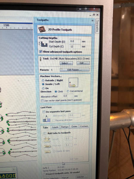
Open the Profile Toolpath.
Set the Cutting Depth to 11.9 mm. Because it’s an internal corner, the Machine Vectors should be set to Inside/Left. And the direction to Climb. The diameter of the cirle is only 13 mm, so I decided not use Tabs for the circles. Click Calculate.
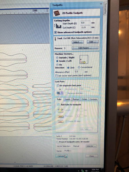
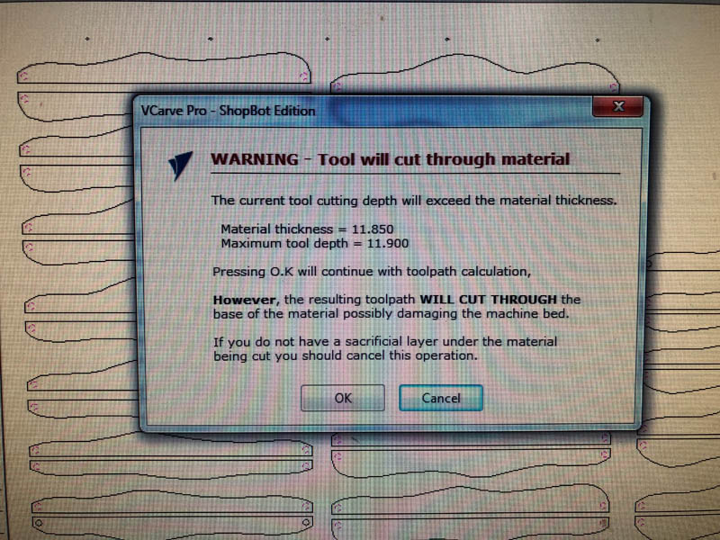
I made the cut depth of this specific toolpath a little deeper, to make sure the tiny holes will be cut out entirely across the board. That’s why VCarve gave this message. Click OK.
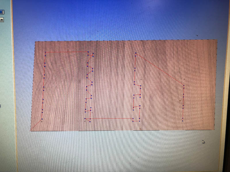
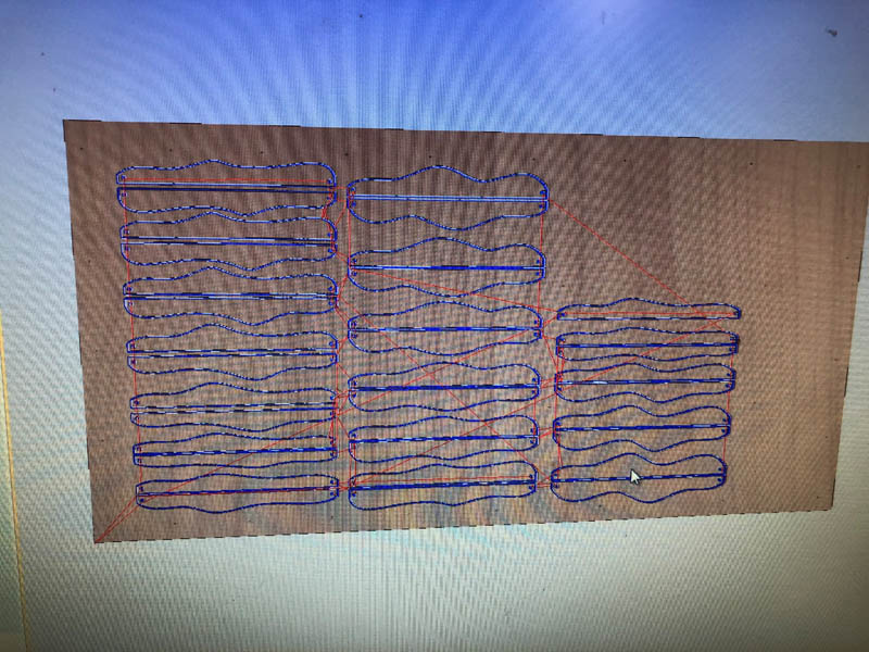
After calculating, the toolpath preview appears.
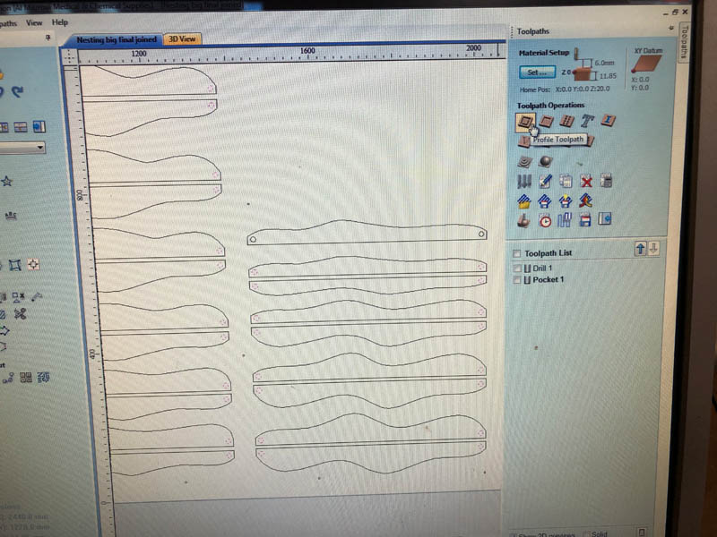
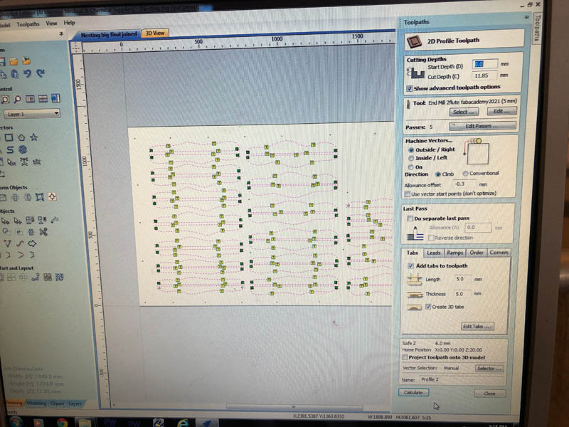
Now we can select all panels and create a second Profile Toolpath.
Set the Cutting Depth to 11.85 mm. The Machine Vectors should be set to Outside/Right because we’re milling the outline of the panels. Set the direction to Climb. We add an Allowance Offset of -0.3 to account for clearance.
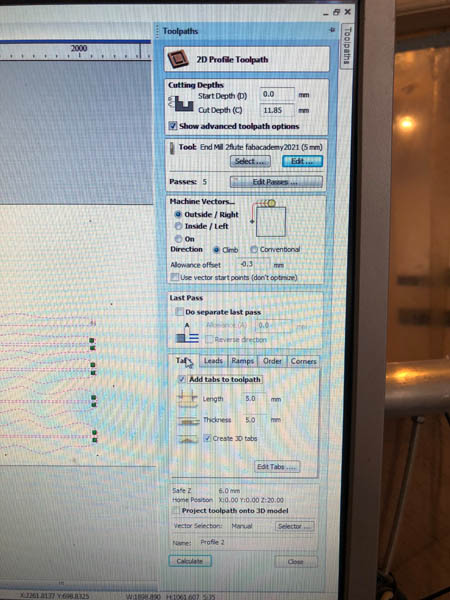
To ease the process of milling, add Tabs to the toolpath. Make them 5 x 5 mm and check Create 3D tabs. To place them, click Edit tabs...
Click Calculate.
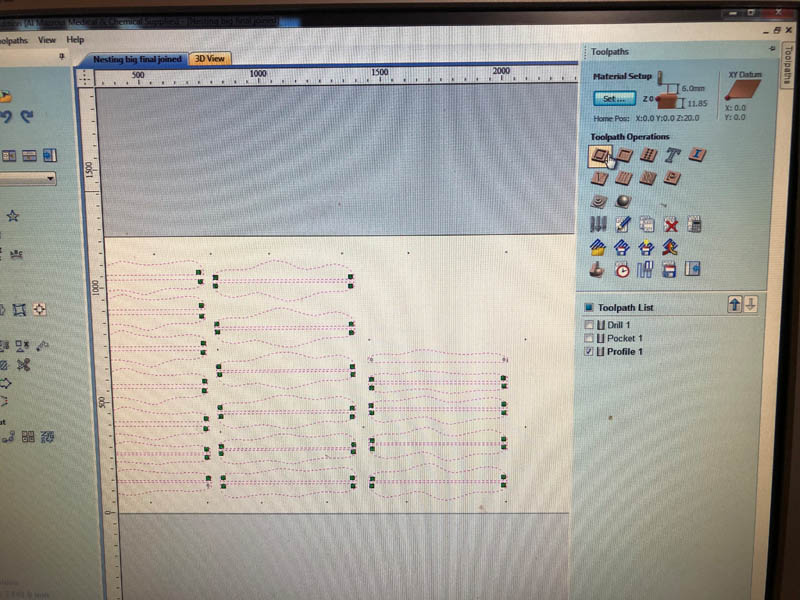
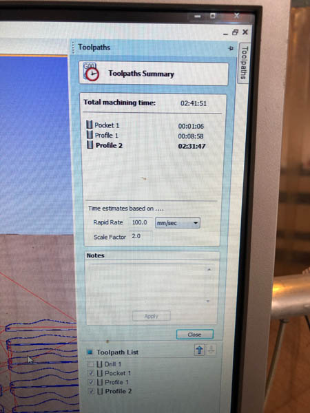
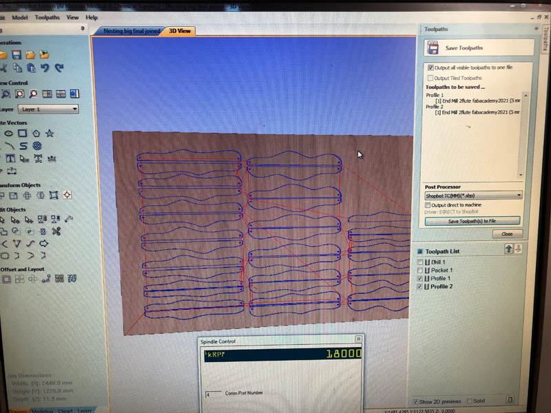
All toolpaths are created now. In the Toolpath Summary, you can see an approximation of machining time.
First, export the Drill toolpath as an .sbp file.
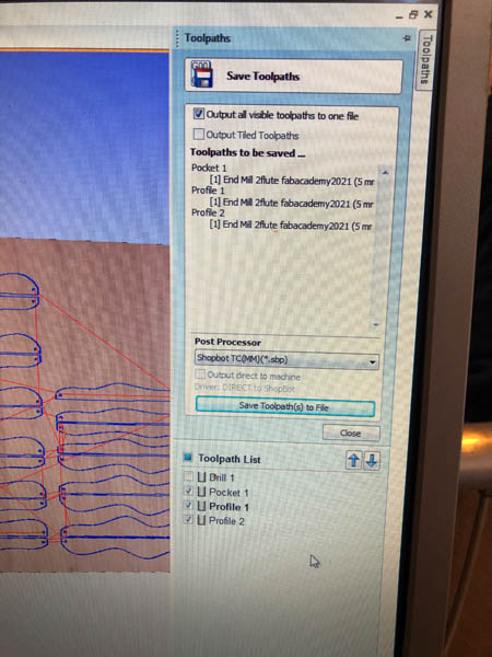
Then deselect the Drill toolpath and select the Pocket and two Profile toolpaths. Check Output all visible toolpaths to one file and save as .sbp file. This last step is really important, because if you accidentally forget to uncheck ‘Drill 1’, the CNC will go to the exact same spot as the screw and hit it. This can cause sparks that set the wood chips on fire.
Logbook Milling
With prepared toolpaths, we can start milling.
Timestamps:
- 14.30 uur Start software vcarve
- 15.30 - 16.08 First milling round for screws (1 minute 6 seconds) and screwing board to sacrificial layer.
- 16:08 - 16:20 uur Milling pockets (8 minutes 58 seconds) & troubleshooting Z-axis (3 mins)
- 16:22 - 17:50 Milling design files profile 1 and 2 (2 hours 31 minutes)
- 17:50 - 18:15 uur Unscrewing and cleaning up
Total time: <4 hours
Detailed logbook:
- Machine slot: 13.00 - 17.00 uur = 4 hours
- Actual start time for measuring plywood: 14.20 uur
- Computer available: 14.30 uur
- Prepare file in Vcarve: 14.30 - 15.30 uur
- Estimated milling time: 2 hours 42 minutes.
- Fixing the bed (remove screws from other student): until 15.15 uur (40 minutes)
- Loaded board on table: 15.35 uur
- First test Z-axis: 15.39 uur
- Send first job to Sjonnie de ShopBot:
Screw Itfile: 15.46 uur - Sjonnie is ready milling: 15.53 uur
- Screws in sacrificial layer done: 16.08 uur
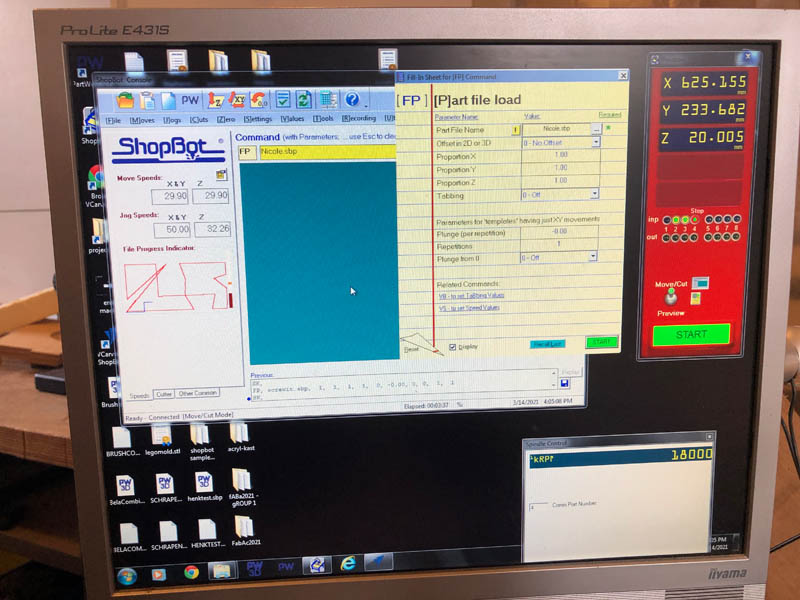
- Send second job to Sjonnie:
Nicolewith pockets and two profiles: 16:10 uur - Notices that Sjonnie doesn’t mill all the way through profile with round 13 circles: 16:15 uur
- Changed
cut depthin vcarve to 12 mm instead of 11.9 mm. - Exported only the two profiles in
Nicole 2: 16:18 uur - Send new job to Sjonnie: 16:20 uur.
- Still not all the way through, Michelle asked if we leveled the Z-axis for a second time. We forgot! Done with leveling 16:21.
- Send job again: 16:22 uur.
- Check if it goes well, which is the case! 16:24
- Done milling: 17:50 uur.
Milling
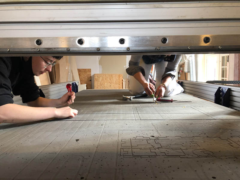
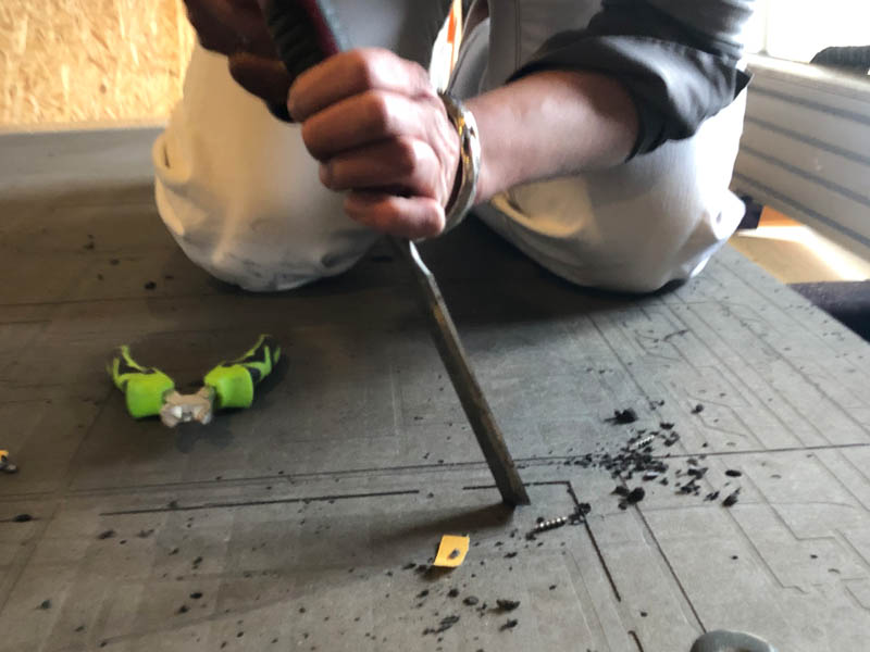
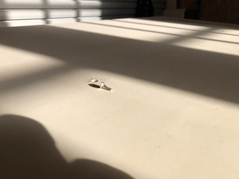
Before I could even start, the bed was full with broken screws from a student from the day before who didn’t clean up. This is dangerous. The student before me was lucky, but my design would probably have hit one of the screws and set the wood chips on fire. It took over 30 minutes with 3 people to remove all screws.
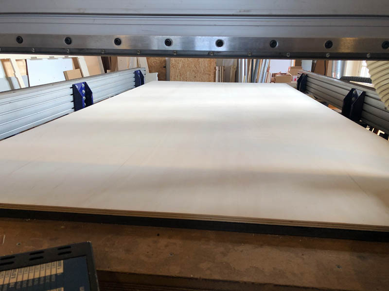
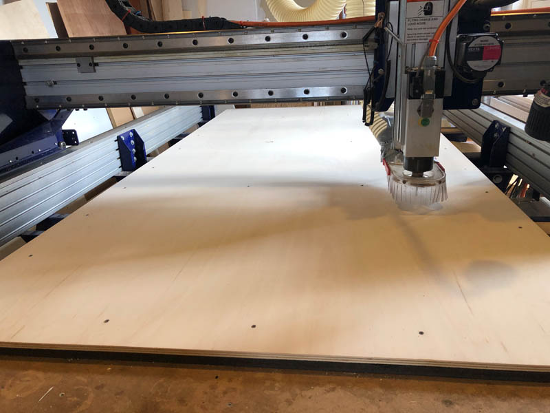
When the bed is clean and flat, the first step is to place the plywood board on the machine bed.
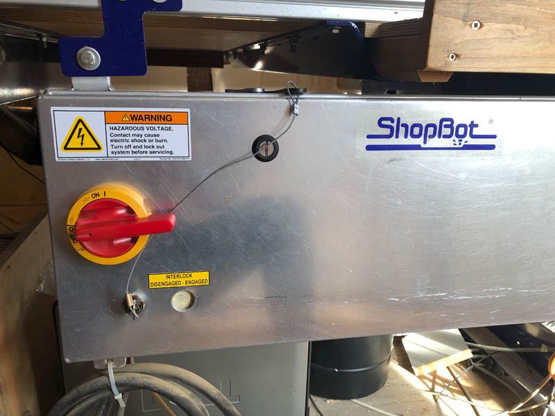
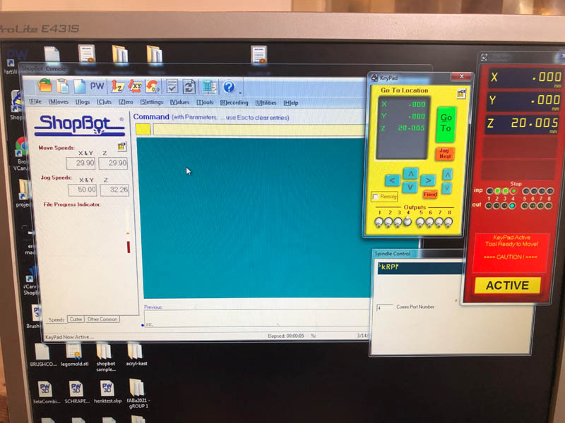
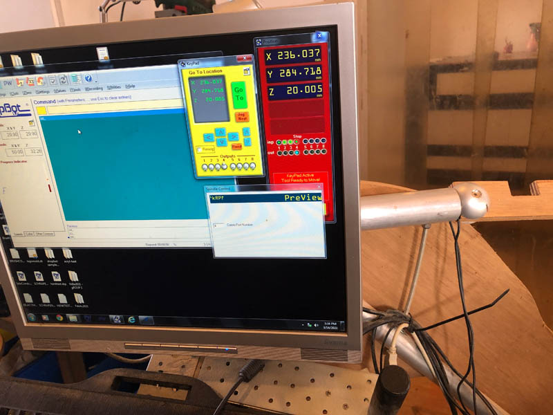
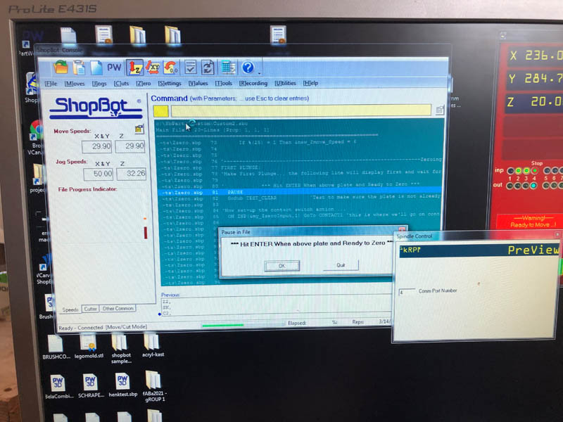
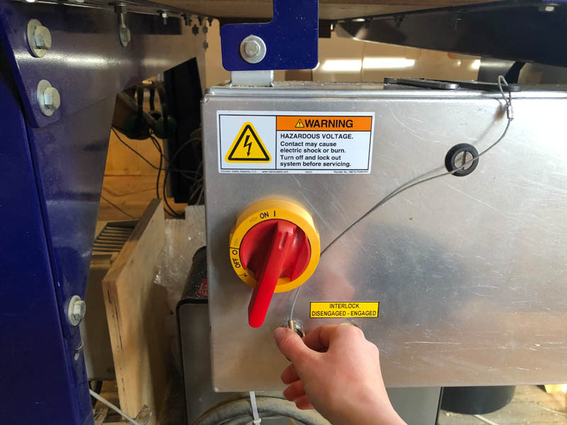
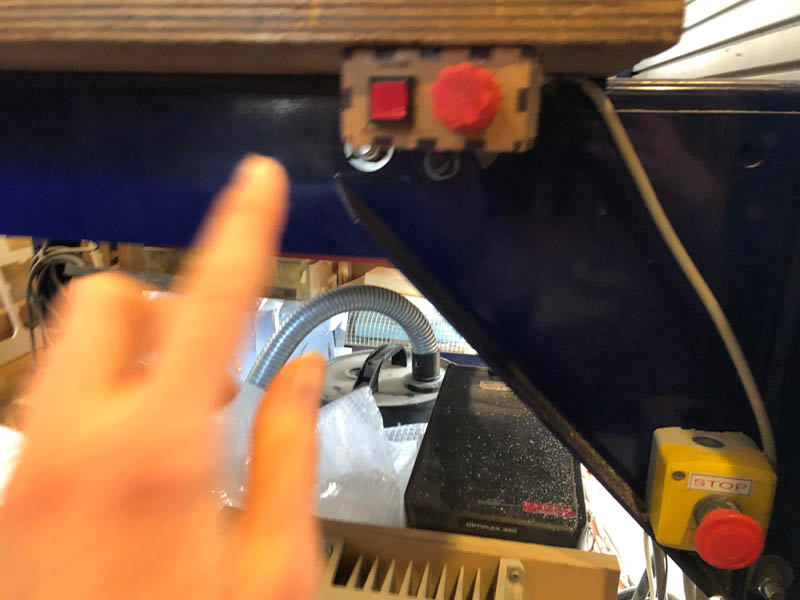
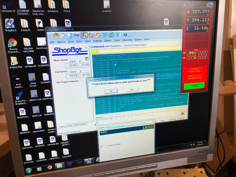
Turn on the red switch to open the ShopBot software.
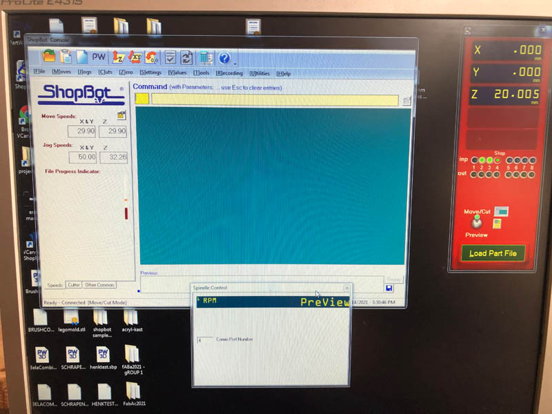
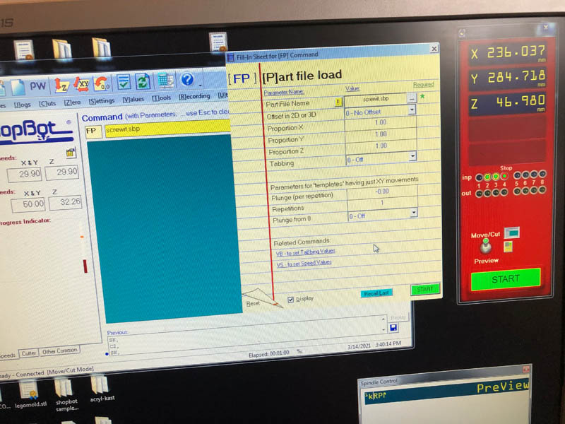
ShopBot will show this screen. Click K to open the yellow keypad.
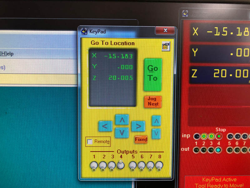
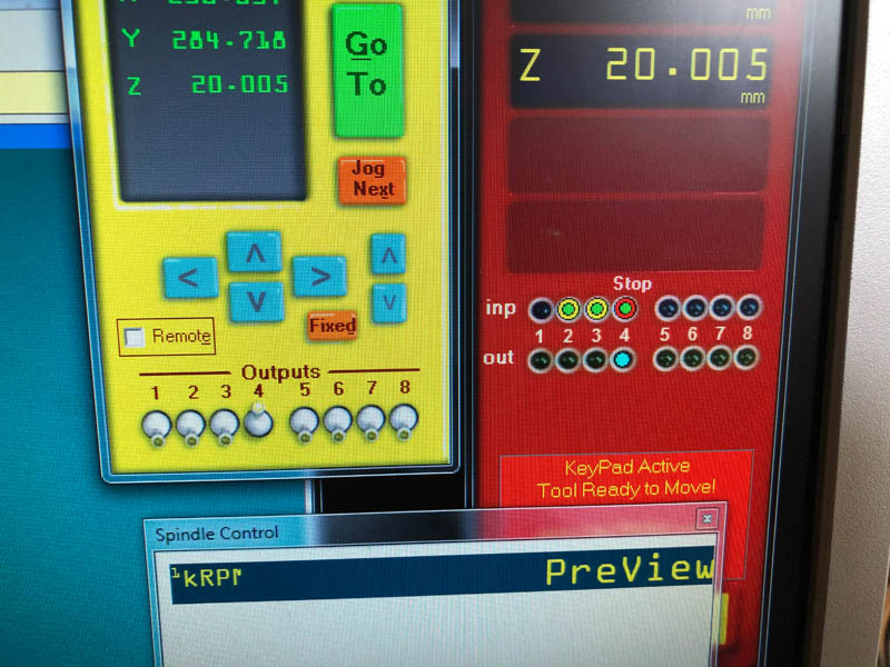
First, we’re going to zero the XY axis. With the keypad, move the drill bit to the corner of the board. Make sure to always take a picture of this screen.
Select zero 2 axes (X & Y).
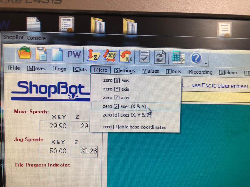
This will put the X and Y position to zero.
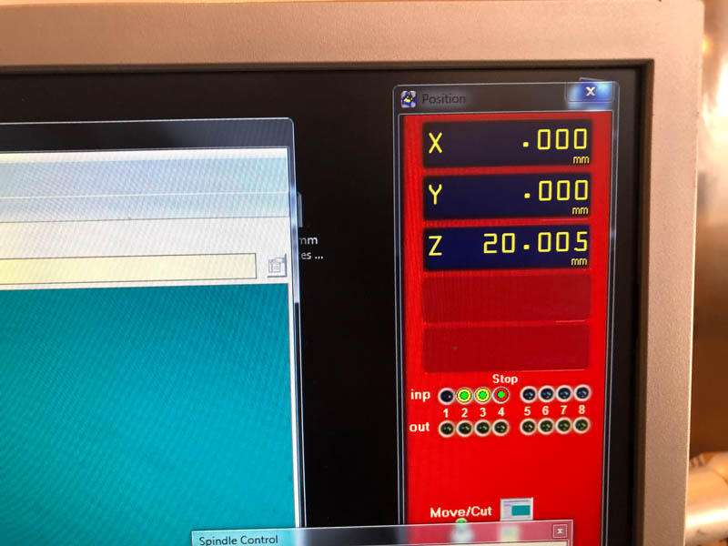
Now we’re going to level the Z-axis. Use the metal tool that’s attached to the machine. Make sure it’s exactly underneath the bit.
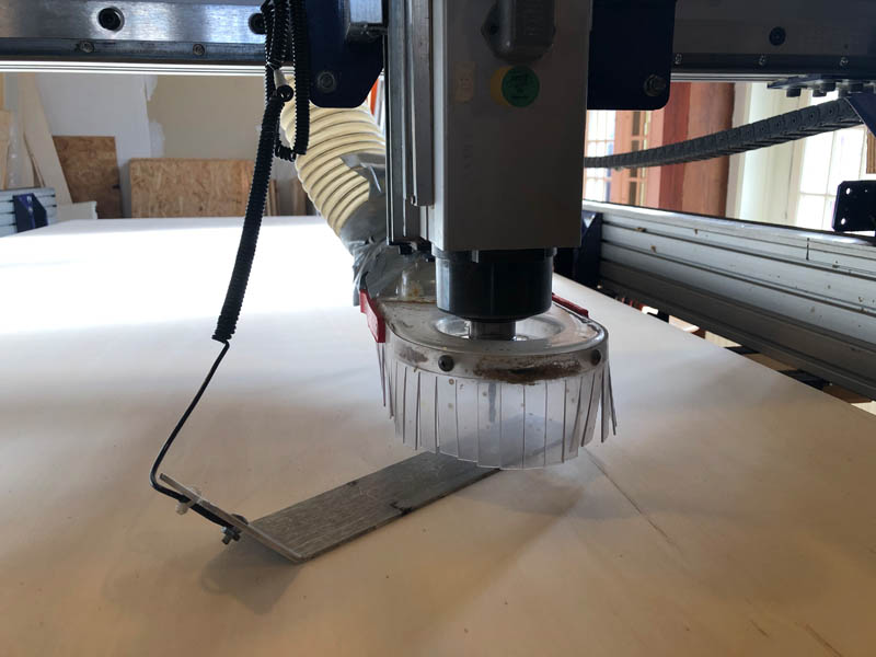
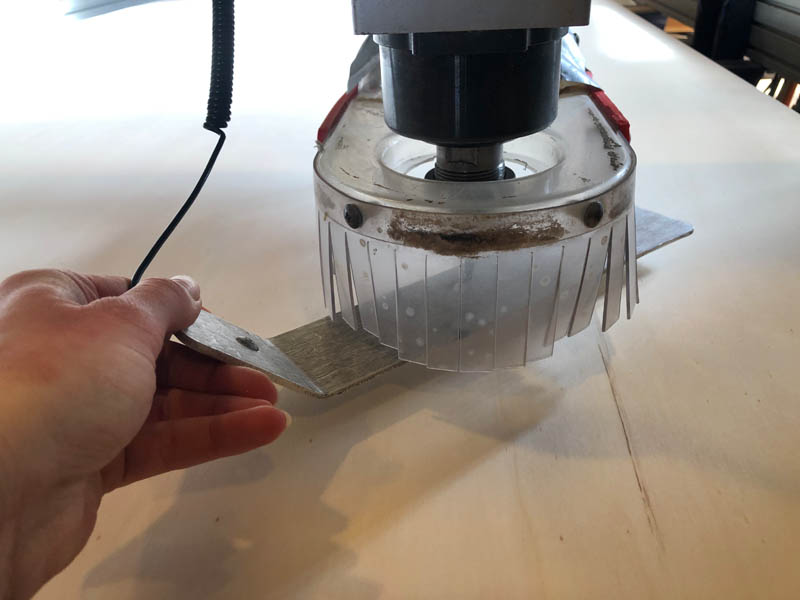
First test if it makes a closed circuit by lifting the metal. If you touch the drill, the light at input 1 should light up.
If it makes a connection, you can proceed with leveling the Z-axis.
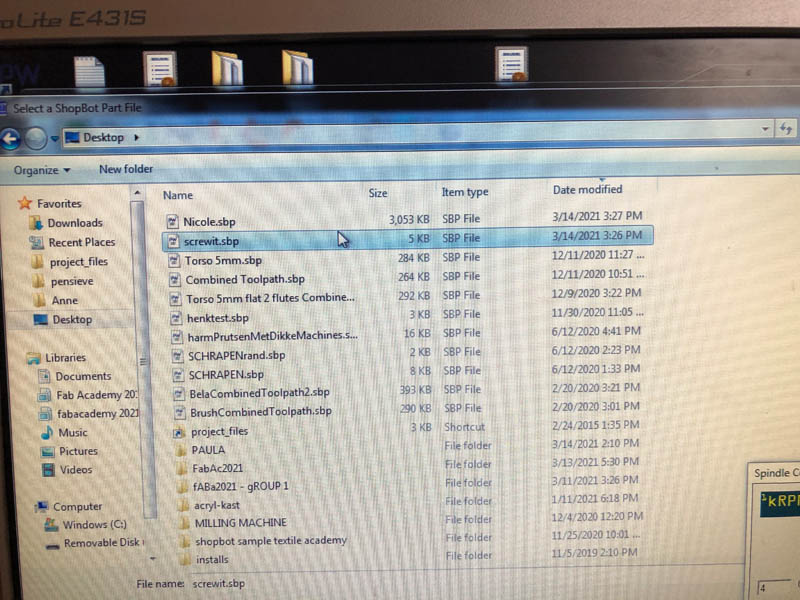
Open the file for pre-drilling the screws.
Then, walk to the closet behind the machine and turn the switch of the ventilation.
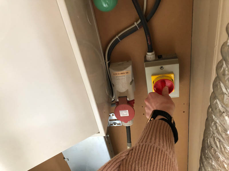
If it’s on, the green light will turn on.
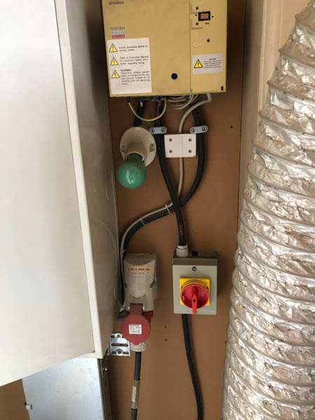
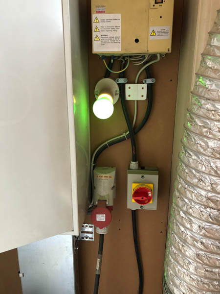
Then turn the key of the CNC’s spindle.
And turn on the switch for the ventilation. It’s located next to the computer.
If you click START the following message appears. Click OK.
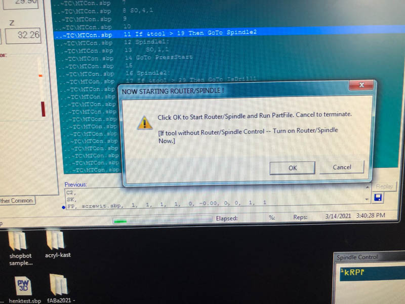
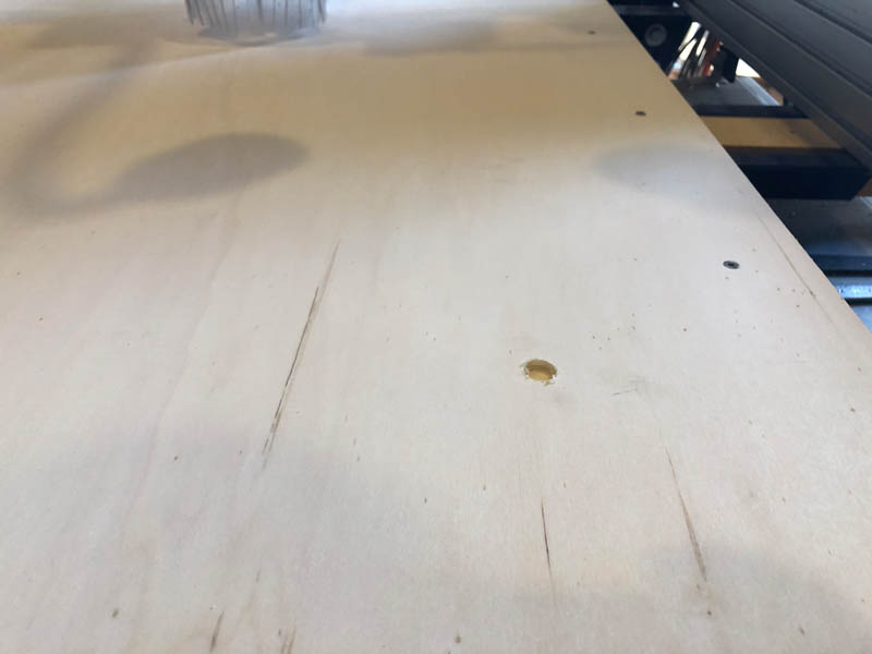
The holes for the screws are now milled.
Use a drill to attach the board to the sacrificial layer. Two screws broke immediately, even without putting a lot of pressure on it. I’m strong, but not that strong!
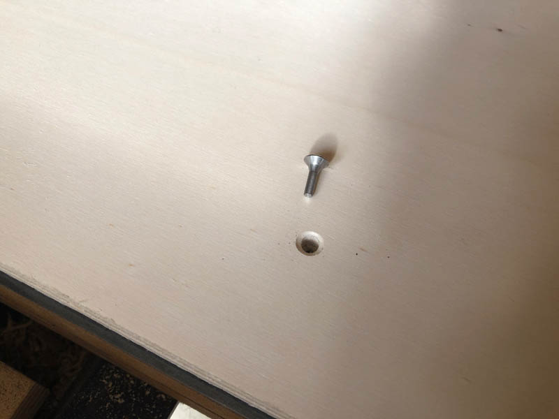
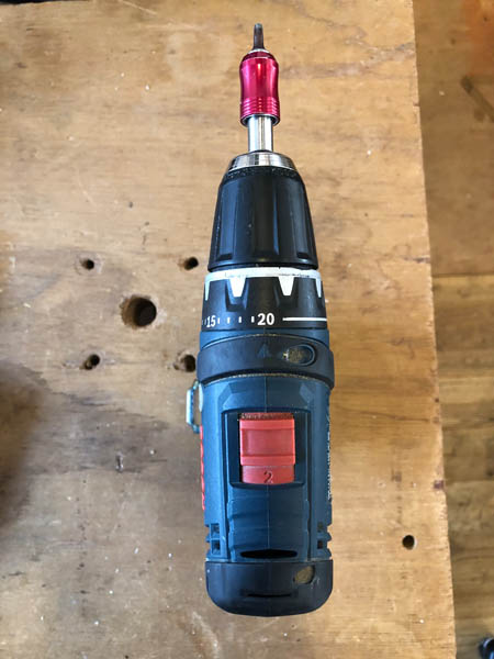
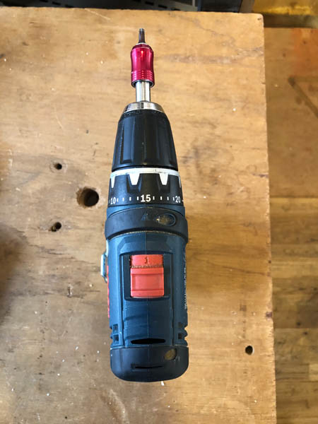
It turned out that the drill’s settings were incorrect. If you set this to 20, and position 2, it will go way too fast and break the screws. I changed the top switch to position 1 and reduced the wheel to 15. This reduces the torque. Problem solved!
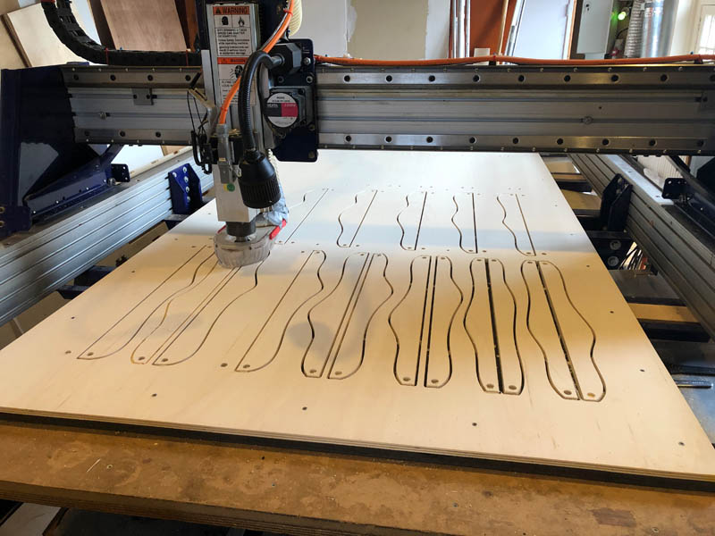
Next, open the other file, with all toolpaths for the paneling.
The first is a pocket, milled out partially.
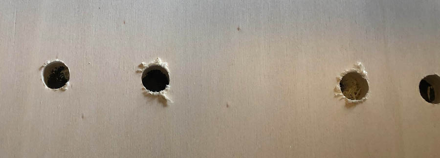
Then the CNC continued with the first Profile, for the holes. The left should have gone all the way through.
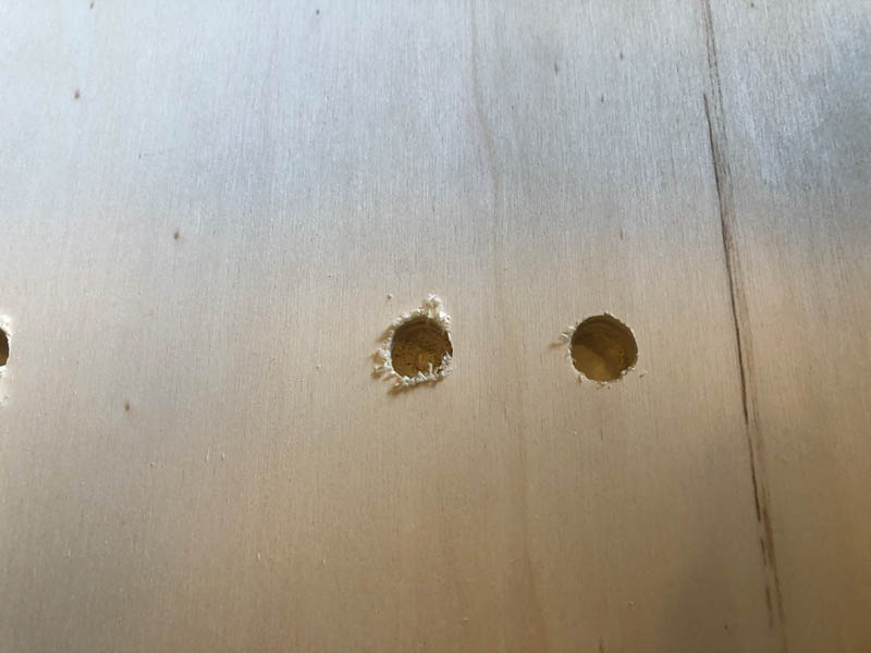
I went back to VCarve, increased the cut depth to 12 mm.
And exported only the two profiles that still needed to be milled.
This still didn’t cut all the way through, and then we found out that we forgot to level the Z-axis after putting in the screws!
After leveling the Z-axis, the machine drilled all the way through.
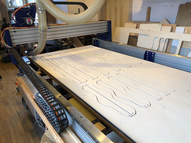
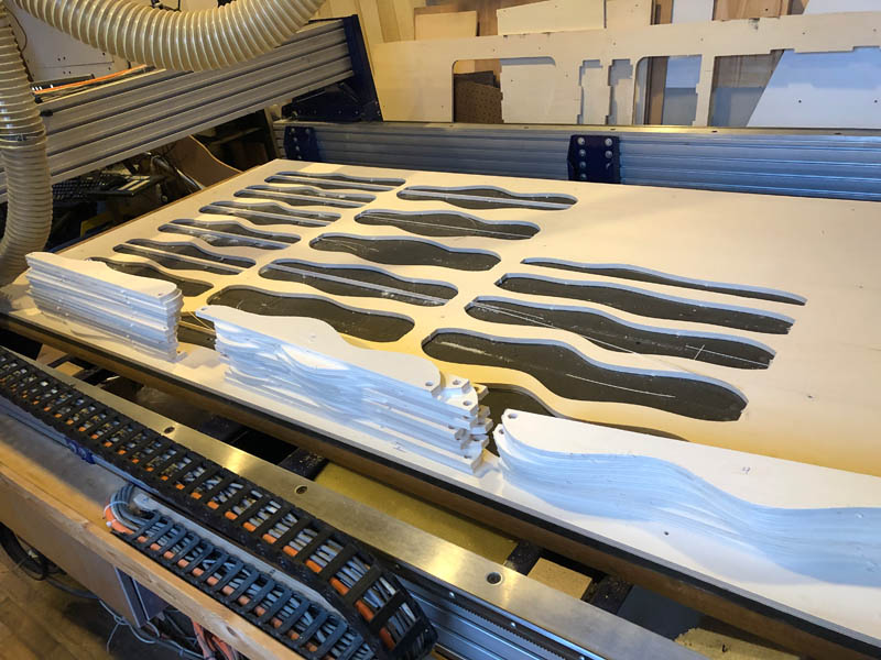
After completing the small circles, it continued with the curvy paneling toolpath.
After completion. Milling took 90 minutes.
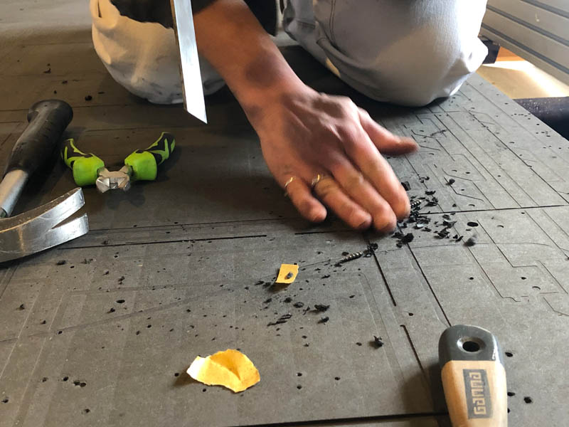
The tabs came out firm and nicely.
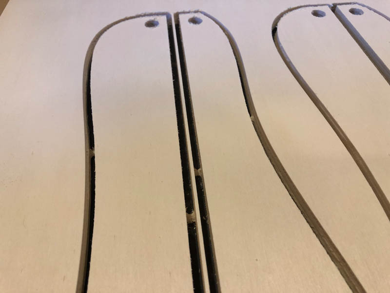
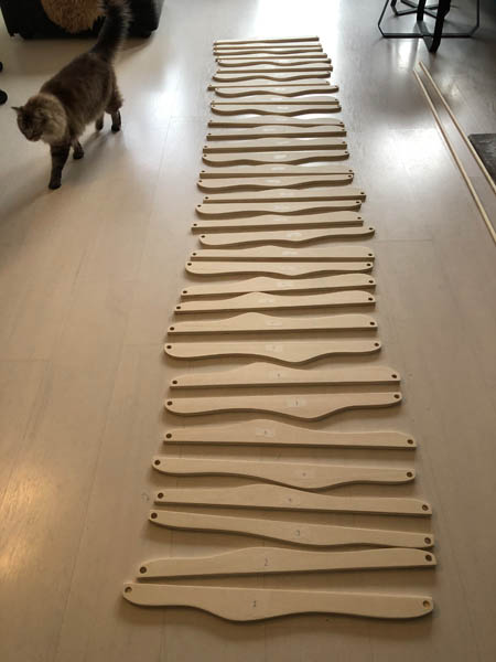
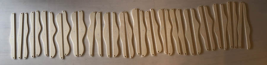
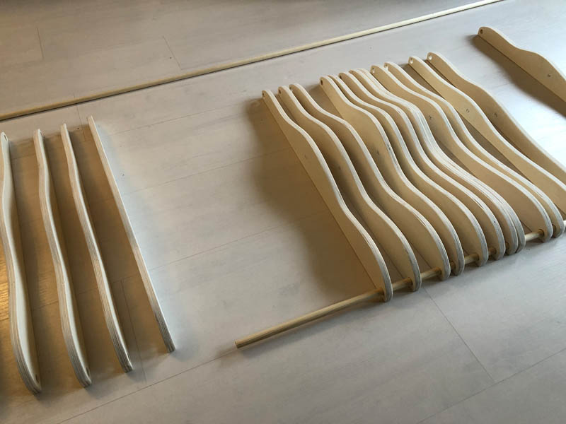
I numbered every piece to be able to sort them afterwards.
Then I collected all pieces, removed the screws and cleaned up.
Summary of what went wrong
- I was supposed to go at 13.00 pm, and couldn’t start until 14.20 because the machine wasn’t available yet.
- Before I could even start, the bed was full with broken screws from a student from the day before who didn’t clean up. This is dangerous. The student before me was lucky, but my design would probably have hit one of the screws and set the wood chips on fire. It took over 30 minutes with 3 people to remove all screws.
- Screws broke off due to drill settings. The Bosch Professional gsr 14.4.4-Li settings: Correct settings: position to 1, turning wheel to 15. Wrong settings: position to 2, turning wheel to 20.
- Job started, pockets were fine. When milling the first profiles (13 diameter circles), it didn’t cut all the way through the material. We forgot to level the Z-axis for a second time after fixing the board to the sacrificial layer.
- No proper ear protection available in the lab. I’ll bring my own next time.
Assembly
The edges of the panels are too rough for assembly, so there was a lot of sanding to do! It took me a full day because I don’t have a sanding machine. It is quite a contrast to work with sophisticated machines on one day, and laboriously sand everything by hand the next. It was a meditative experience!
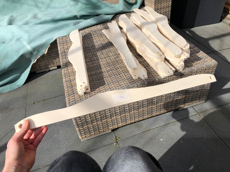
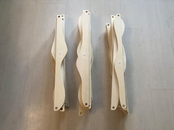
Panels ready for assembly.
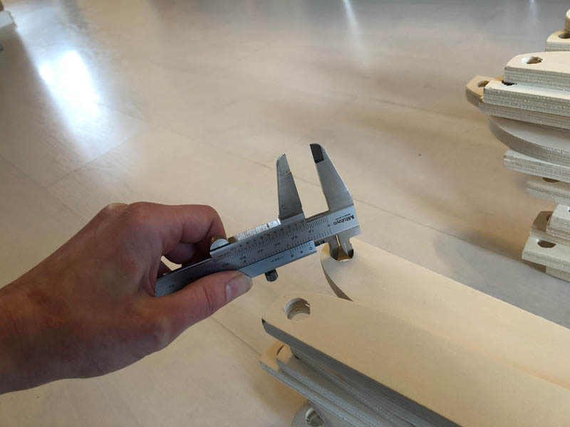
Measure the internal diameter of the holes with a caliper, to check if the ⌀12 mm rod will fit. Surprisingly, they are exactly ⌀13 mm.
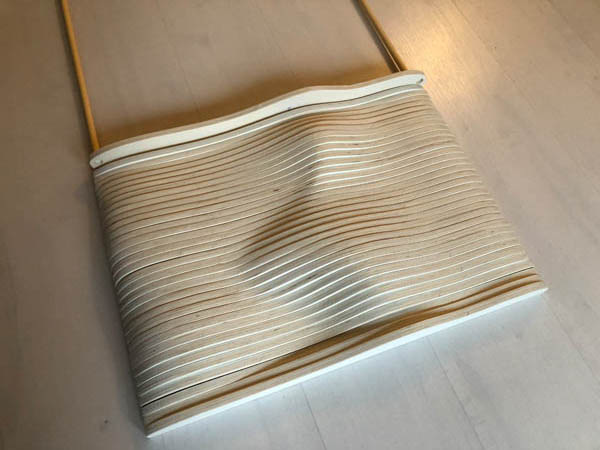
Align all numbered panels in the right position.
Moving the rod through the circles.
It’s easiest to lift the artwork to another room on the second floor when the panels are pushed together.
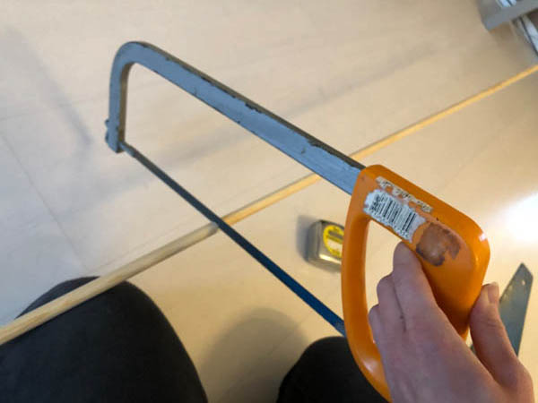
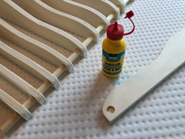
Make the rod on the right length of 1700 mm.
Glue the ends with wood glue.
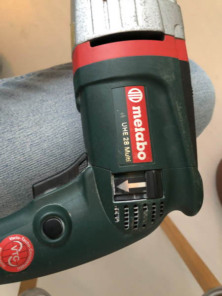
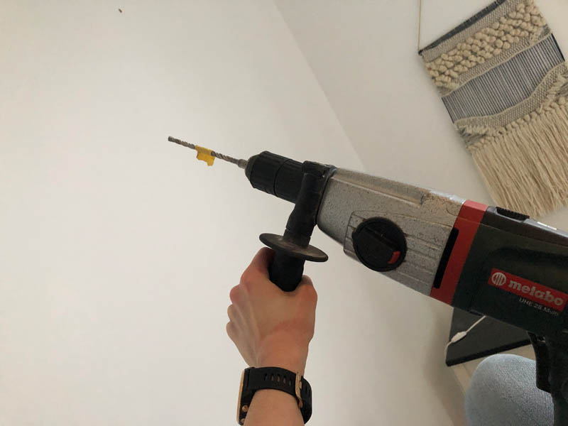
Because of the concrete walls, I need to pre-drill holes.
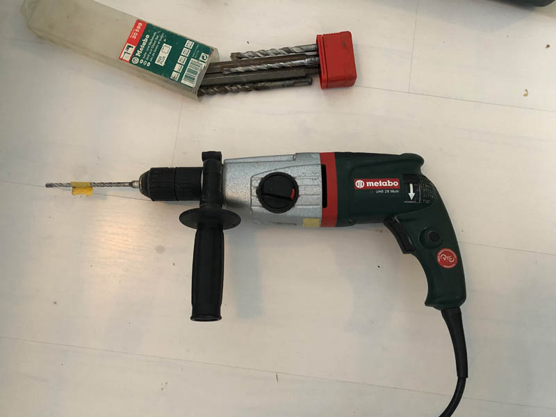
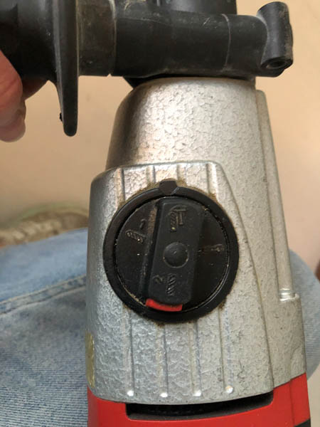
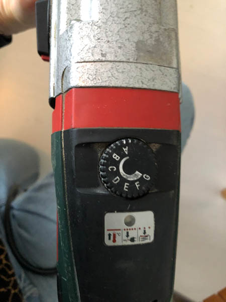
This is more for my own documentation because I’m borrowing this drill and the settings are always different. Use the black drill bit holder, switch to hammer, speed to E and the switch up.
Here we go. I always use PPE, such as safety glasses and ear protection.
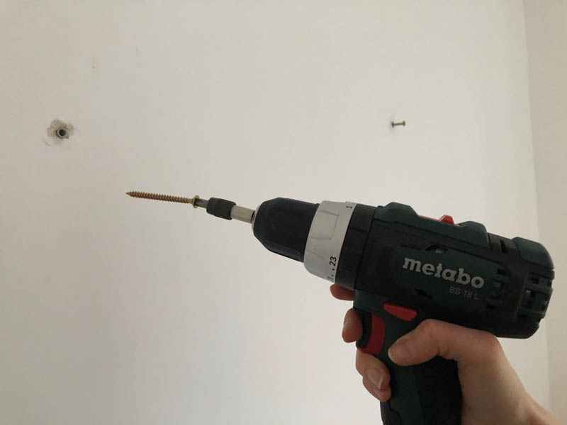
Now we can put in the screws. Hammer the plugs first.
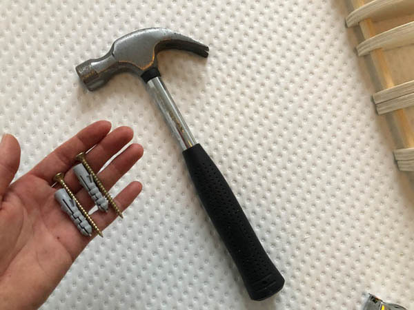
Then add the screws.
Final result!
Downloads
Explore more like this
Week 17 Invention, Intellectual Property and Business Models
After acing through the technical assignments of Fab Academy, the last two weeks have a lighter load so we can focus on the final project. But this does not mean...
Week 16 Applications and Implications
Propose a final project masterpiece that integrates the range of units covered, answering: