
Embedded Programming
Group assignment:
- - Compare the performance and development workflows for different microcontroller families.
- - Read the datasheet for the microcontroller you are programming.
- - Program the board you have made to do something, with as many different
programming languages and programming environments as possible. - Arduino IDE
Individual Assignment
Software used:
Group Assignment
Group Page LinkIndividual Assignment
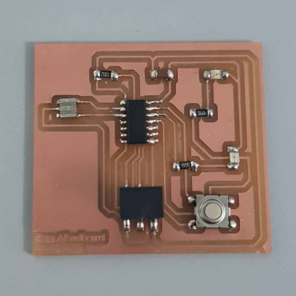
In this week, I programmed the board I designed in Week7 by usign the FabISP programmer board from Week5 .
 |
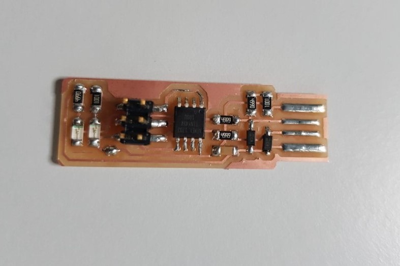 |
| My PCB that I will program it in this week | FabISP Programmer |
DataSheet
Before programming, I started reading the Datasheet of the microcontroller I'm using which is the ATtiny44.- From the first page, I can see a summary of the features, and I can find the operating voltage in V and the speed in MHz. These two features help me to select the suitable resonator with the best speed to use it in the PCB. In addition, to avoid applying voltage more than the operating voltage of the microcontroller.
• Operating Voltage:
2.7 – 5.5V for ATtiny24/44/84
• Speed Grade:
0 – 10 MHz @ 2.7 – 5.5V
0 – 20 MHz @ 4.5 – 5.5V
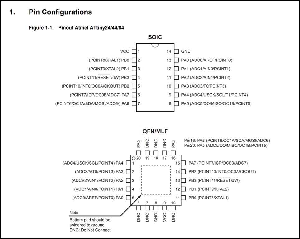
I can also understand the pinout of the microcontroller from the Pin Configuration and I can see where the pins are located physically.
There are Analog input pins that includes ADC that converts analog signal to digital signal.
Analog input pins: Port A pins (PA0, PA1, PA2, PA3, PA4, PA5, PA6 and PA7). They include Analog to Digital converter (ADC).
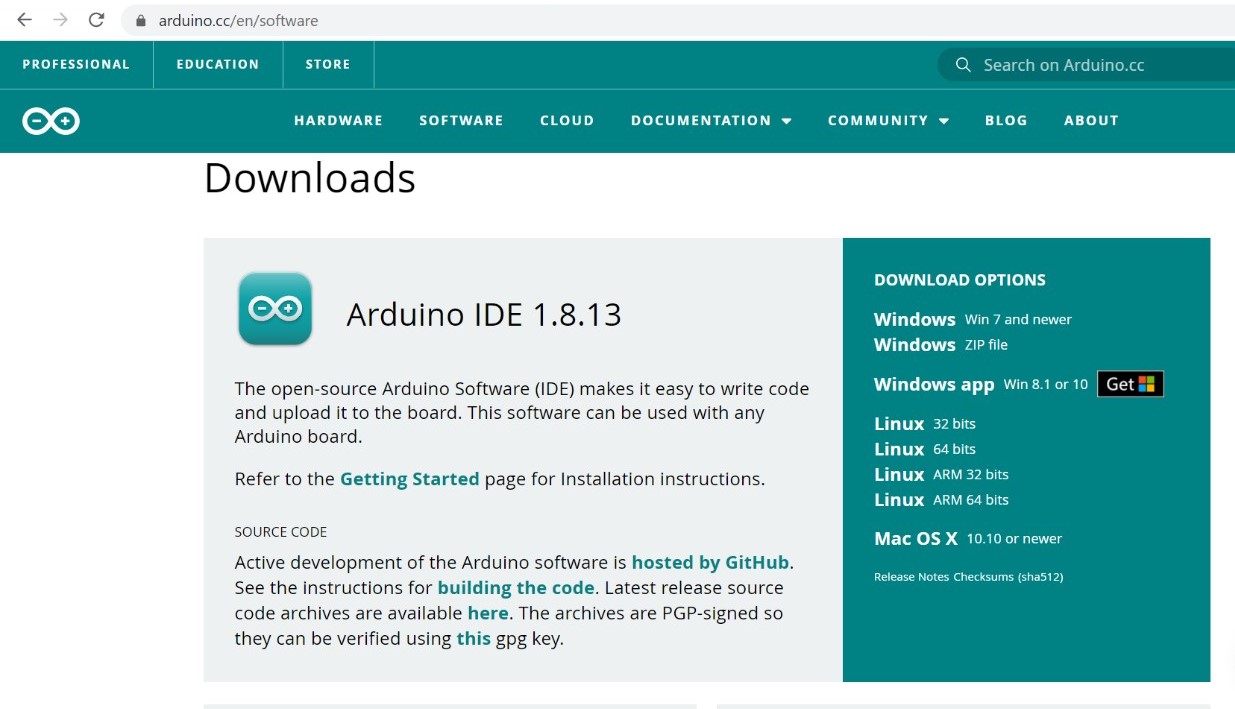
There are many software used for programming and I choosed to use Arduino IDE software.
So the first step is to install the Arduino IDE software
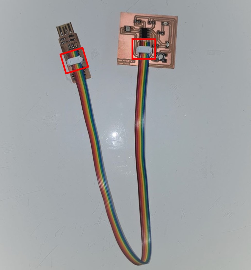
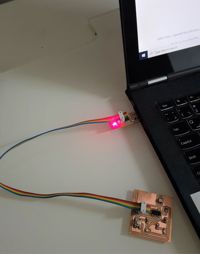
The next step is to insert the FabTinyISP in the PC and connect it with my PCB through ribbon connector.
The image in the left shows how I connected the ribbon connector. It's important to make sure that the header in both PCBs have same orientation.
After that, I opened the software Arduino IDE and I added the microcontroller that I will be programming which is ATtiny44 in the software.
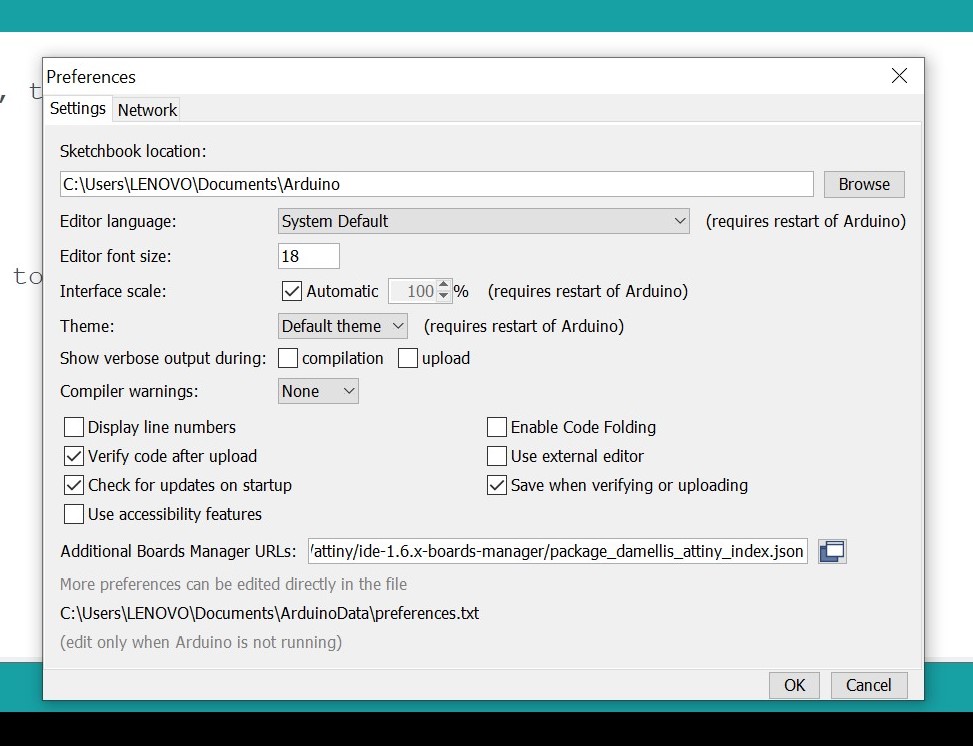
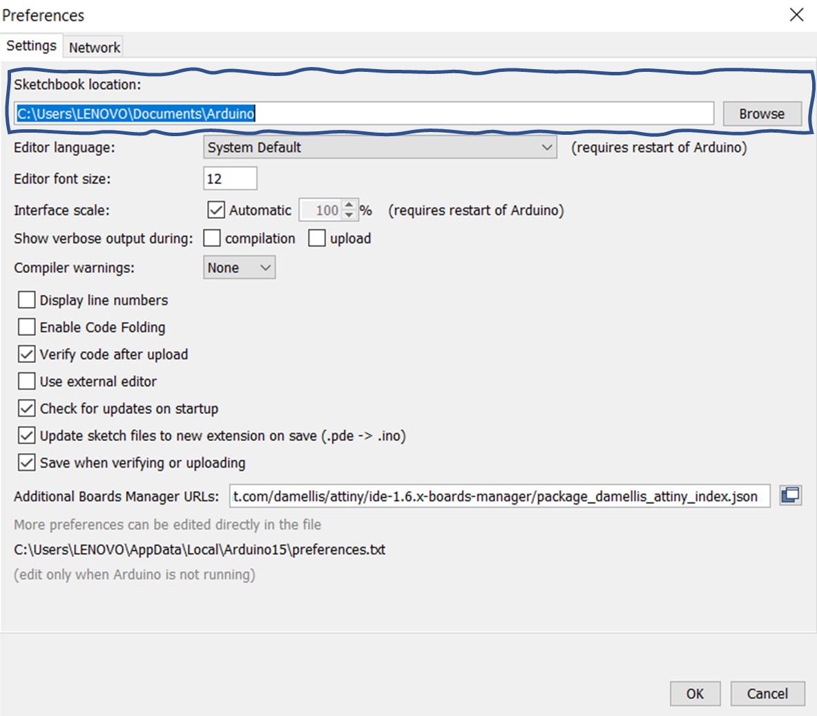
1. I went to File >> Preferences >> go down to Additional Boards Manager URLs >> paste the following URL >> Ok
https://raw.githubusercontent.com/damellis/attiny/ide-1.6.x-boards-manager/package_damellis_attiny_index.json
2. Then I went to Tools >> Boards >> Board Manager >> scroll down to attiny >> click Install
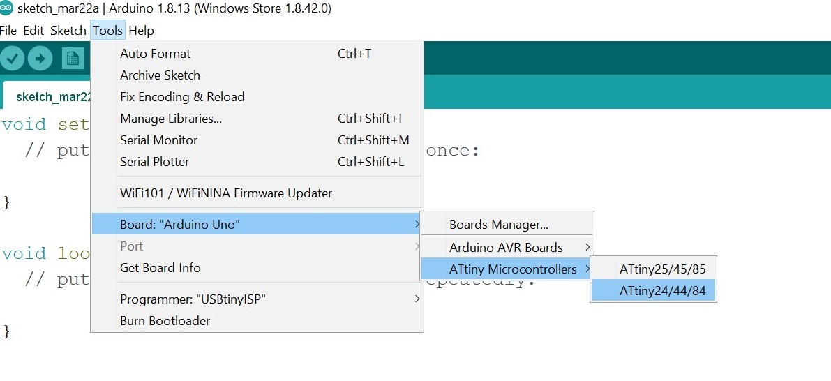
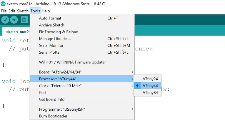
3. After that, I went to Tools >> Board: >> ATtiny Microcontrollers >> ATtiny24/44/84
4. Again I went to Tools >> then Processor >> ATtiny44
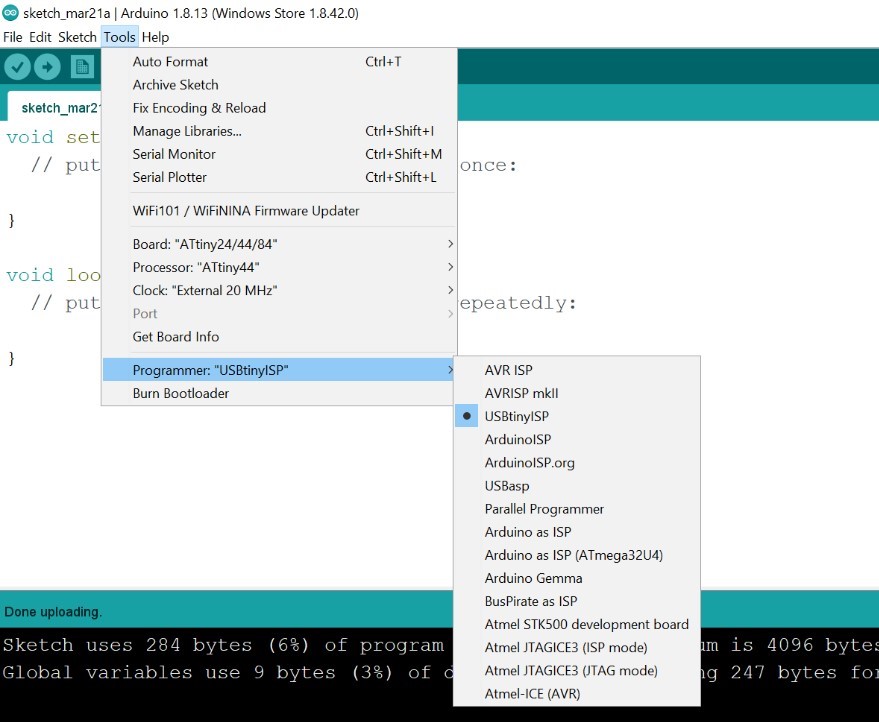
5. Tools >> Programmer >> I chose to program my PCB by using USBtinyISP
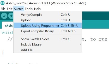
6. Then I went to Sketch >> Upload Using Programmer
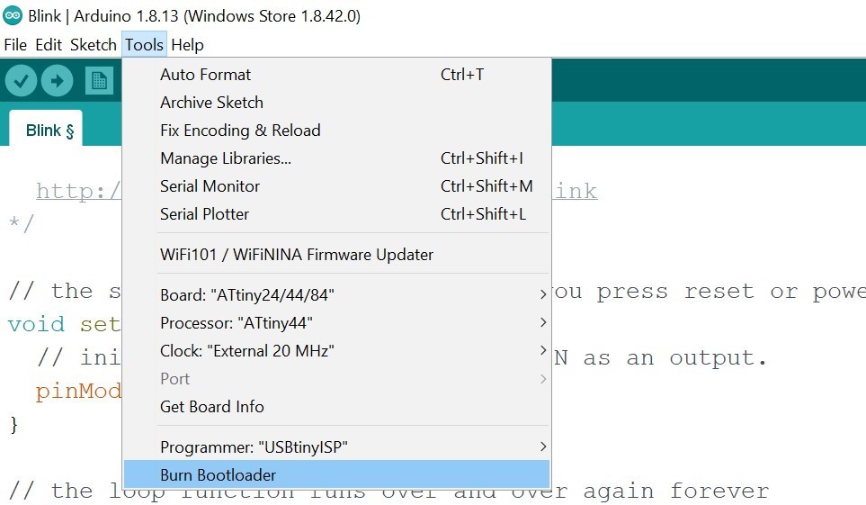
7. Finally I burned the Bootloader by going to Tools >> Burn Bootloader
Now is time to test my PCB. I selected the blink code from the examples available in Arduino IDE.
Then I wrote the number of the pin that the LED is connected to in my board.
In my PCB design I connected two LEDs, one to pin number 1 and the other one connected to pin number 2, so I can choose any one of them.
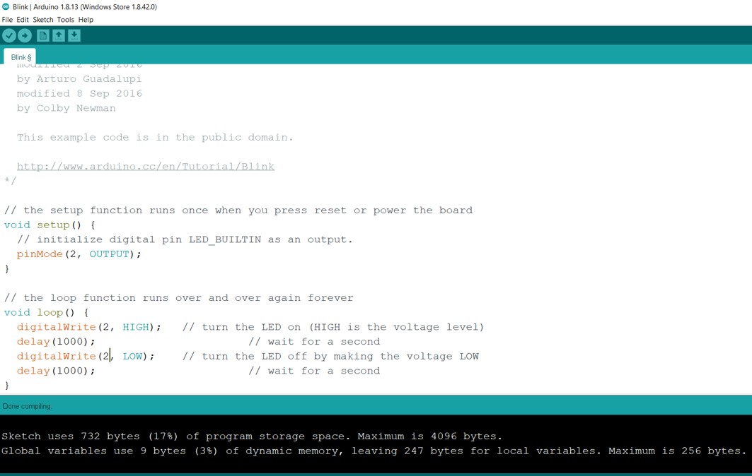
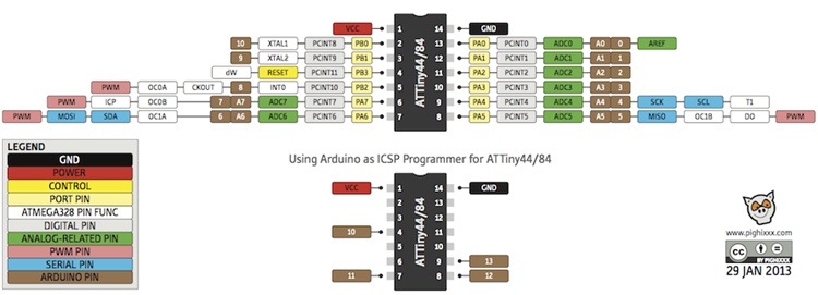
By referring to the following ATtiny44 pinout image, pin A2 in ATtiny44 is also pin number 2 in Arduino. Therefore, in the code I made LED pin equals to 2.
Finally I uploaded the code to my PCB.
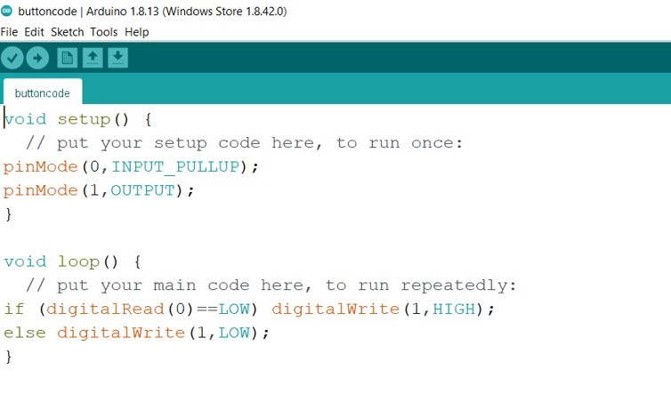
Button
Here I wrote a simple button code by my own and I upload it to the board.
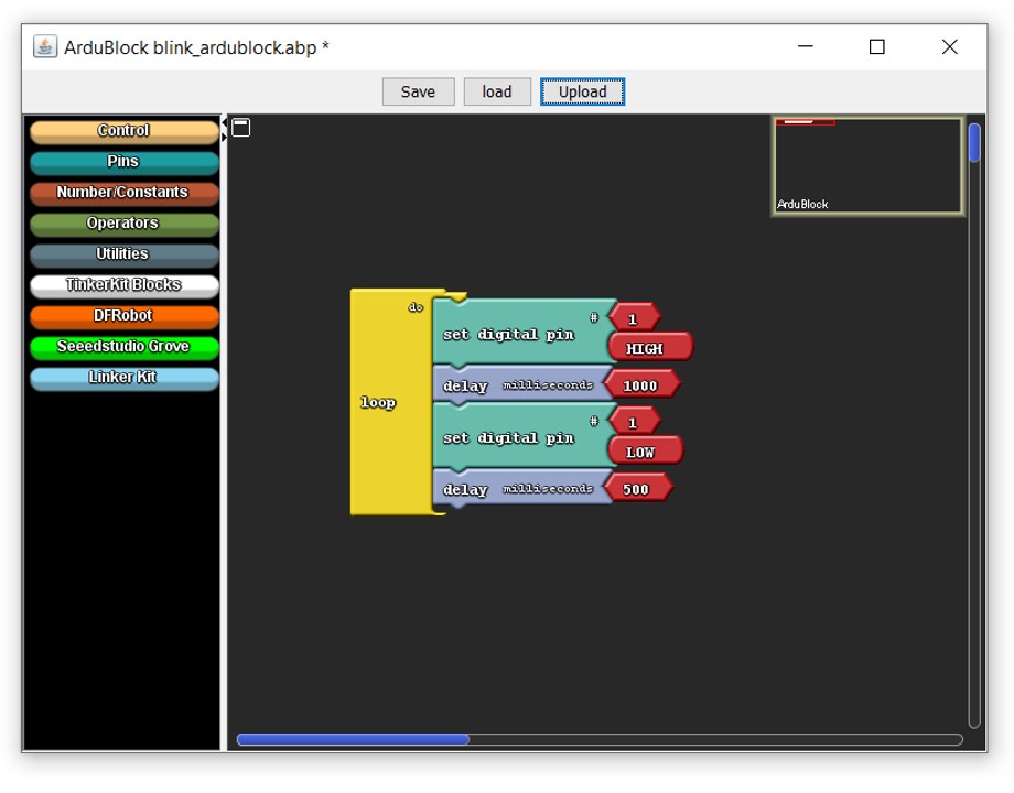
ArduBlock
Ardublock is a graphical programming language for Arduino.I followed the steps in the Ardublock website to install it.
And I red Maha's documentation. She wrote that ArduBlock doesn't work with (Arduino 1.8.10) version. So she installed (Arduino 1.6.9) version and ArduBlock successfully worked. I tried to use Ardublock with (Arduino 1.8.16) version and it doesn't work, so I installed the 1.6.9 version as Maha did and it worked with me.
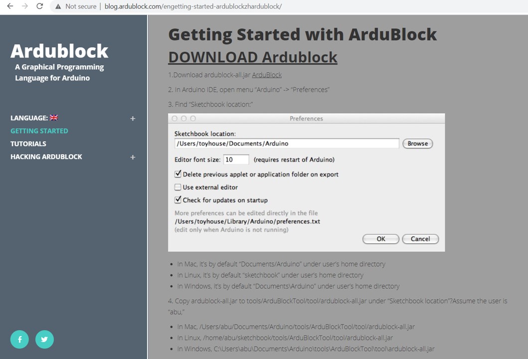
1. I downloaded ardublock-all.jar from the website
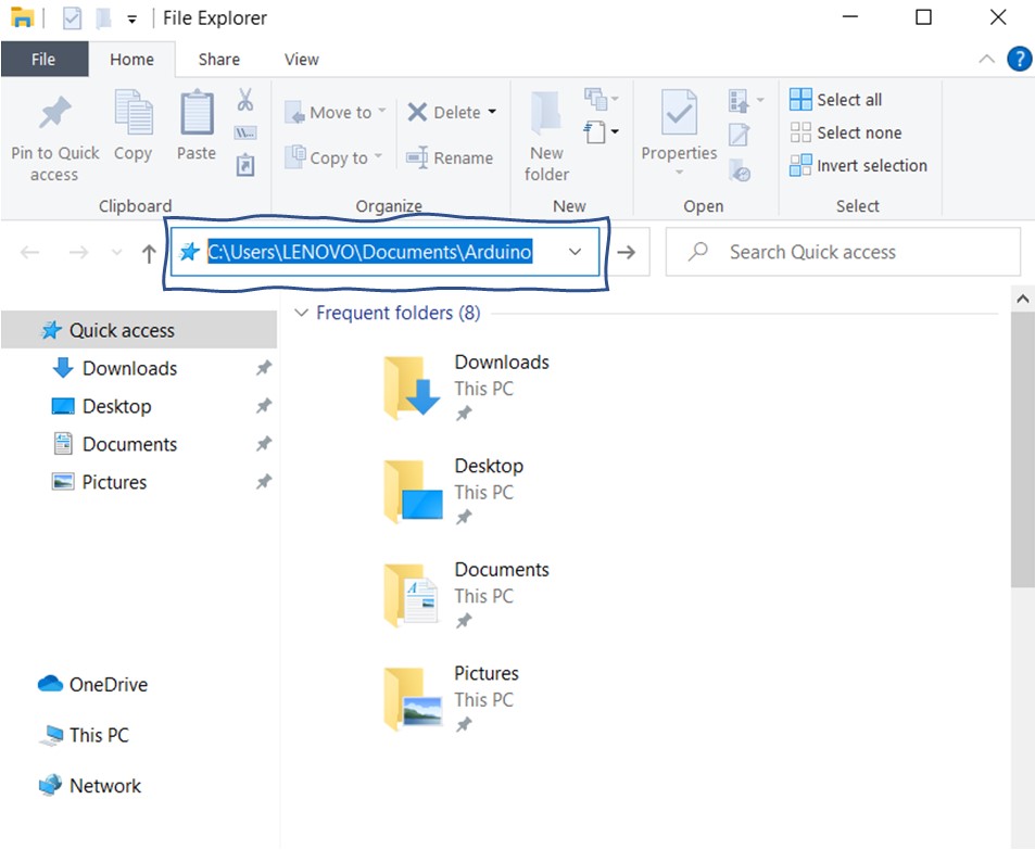
2. Then I opened Arduino software >> File >> Preferences >> I copied the Sketchbook location
3. I pasted the location in File Explorer as shown in the following image and I pressed Entre
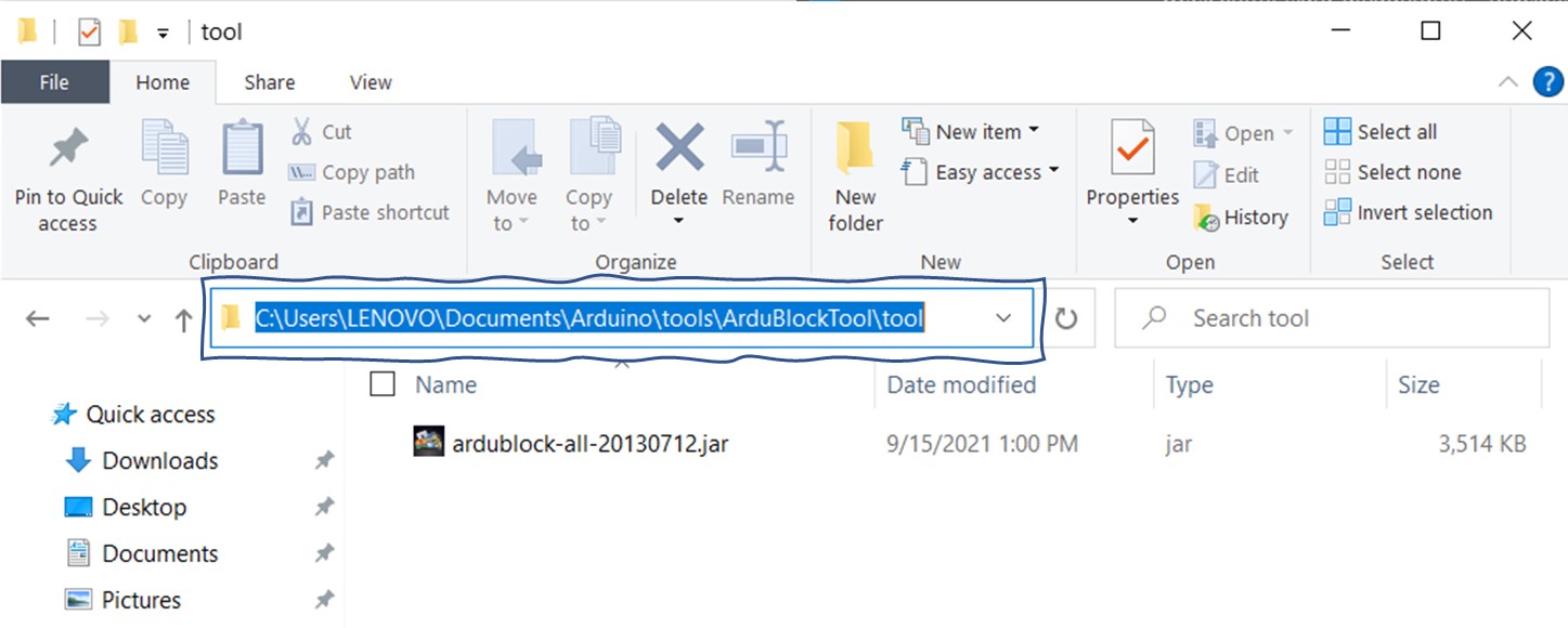
4. Then I created a folder and I named it tools. Inside tools I created another folder and I named it ArduBlockTool. Finally I created a folder with name tool inside ArduBlockTool folder and I paste the ardublock-all.jar file that I downloaded in the first step into tool folder as shown in the following image
Now its time to close Arduino software and reopen it again >> then I went to Tools and found ArduBlock there. I clicked on it to open it. The following image shows how it looks like.
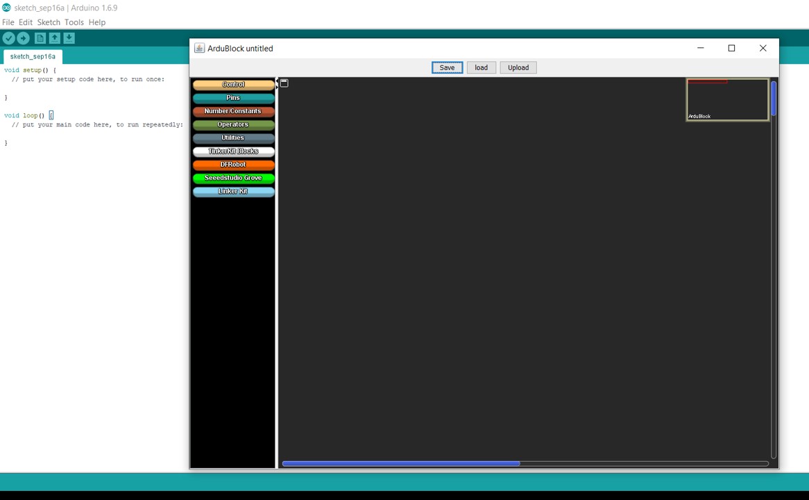
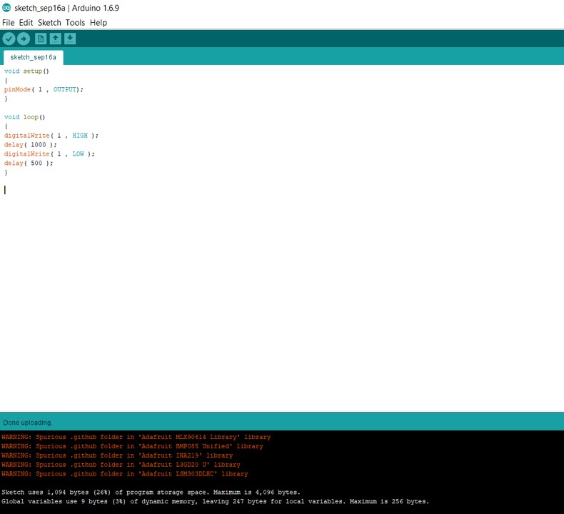
I did a simple blink code. Then I clicked on Upload. The code blocks are translated into Arduino language as ahown in the following images.
Files list:
| Blink code | Arduino File |
| Button code | Arduino File |
Close Project