
Final Project
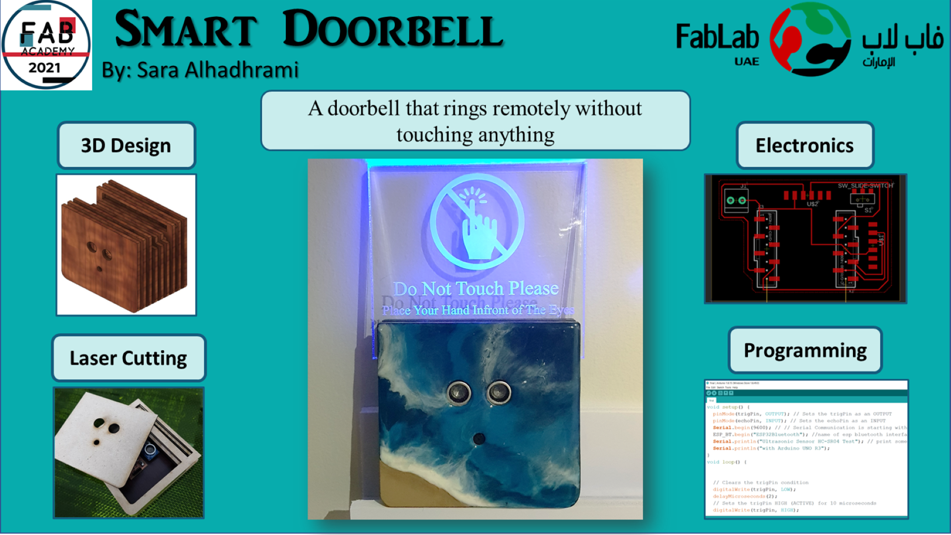
Smart Doorbell
A smart doorbell that sense the existence of a person automatically and generates the doorbell sound. This project consists of an outdoor doorbell device and a smart phone application. The outdoor device will sense objects and transmit signals through wireless communication to the smart phone to generate the bell sound immediatly as it receives the signal.
Electronics
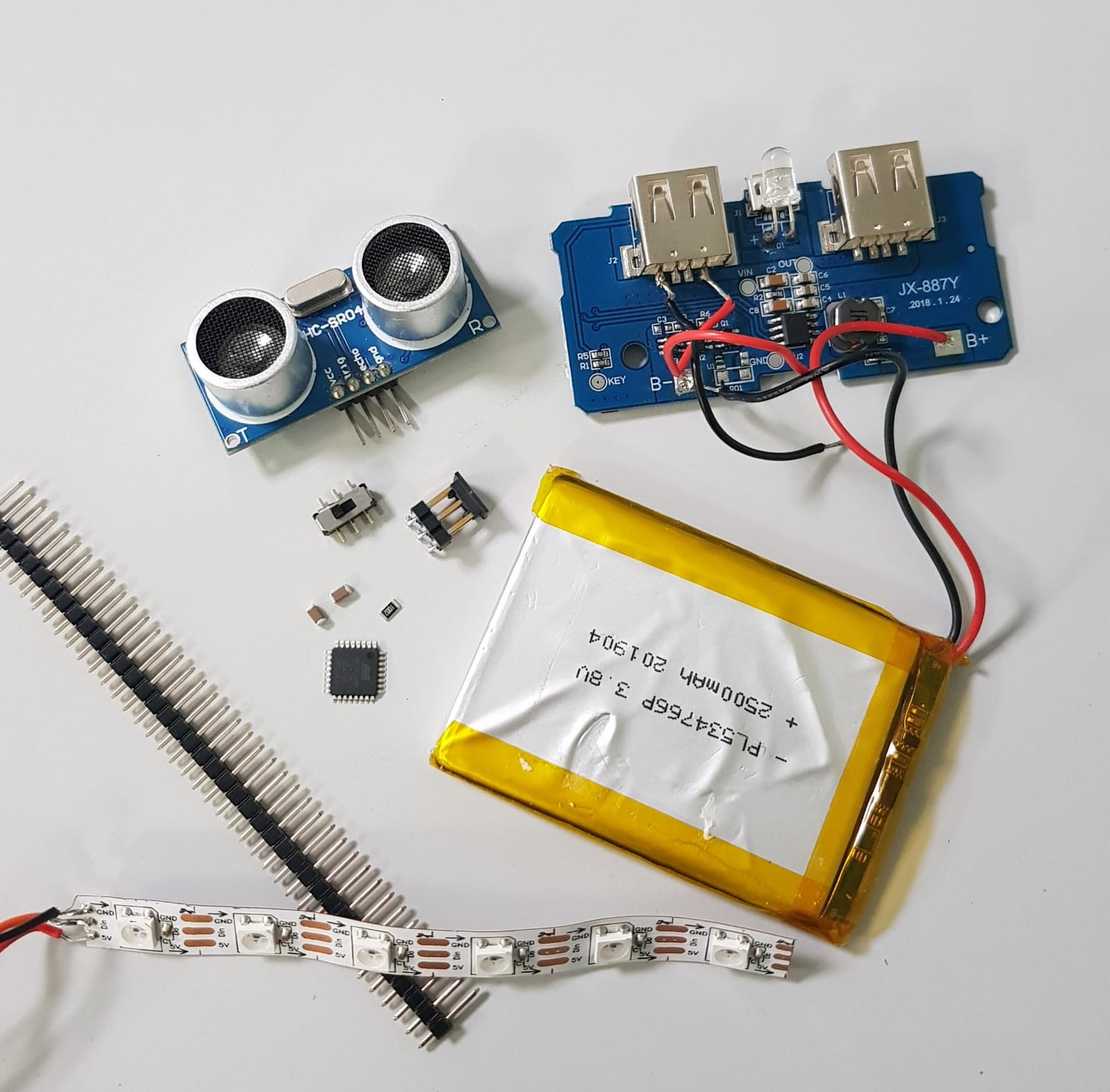
Consists of:
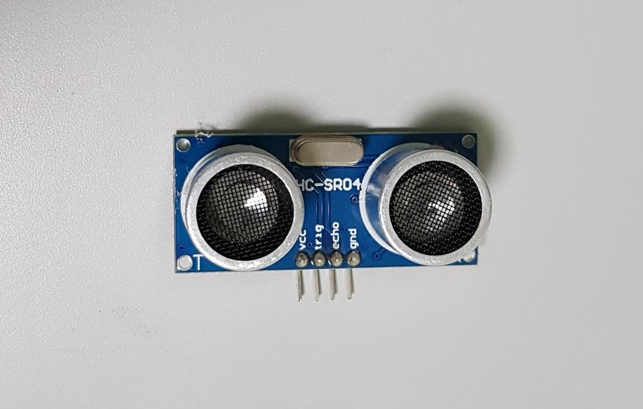
- ATmega328P- Ultrasonic sensor
- Slide Switch
- Headers
- 10K resistor
- 2X 1uF capacitors
- 2500mAh Lithium Ion (LiPo) Battery
- 5V Boost for Lithium Battery JX-887YDC Boost Converter
- Neopixle LEDs strip
- Bluetooth module HC-05
I used Autodesk Eagle to design a PCB for the device.
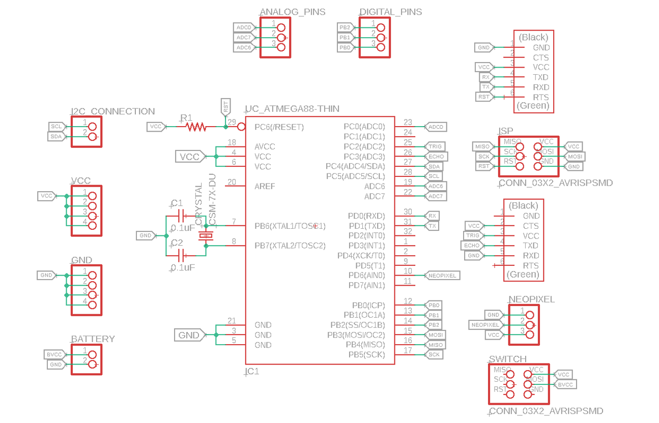
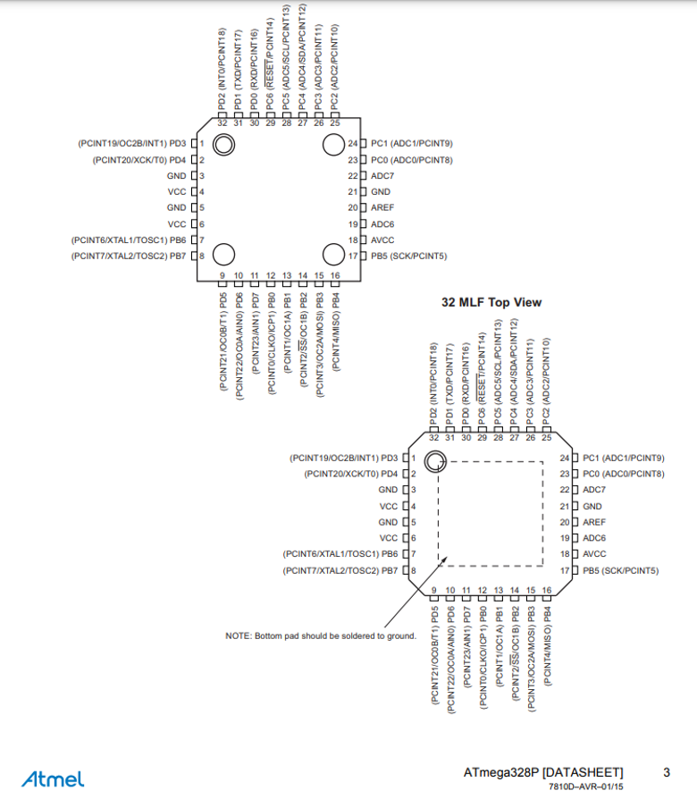
I used Atmega328P Datasheet to find the pinouts of the microcontroller. From the datasheet I knew the digital pins, analog pins, VCC and Ground pins.
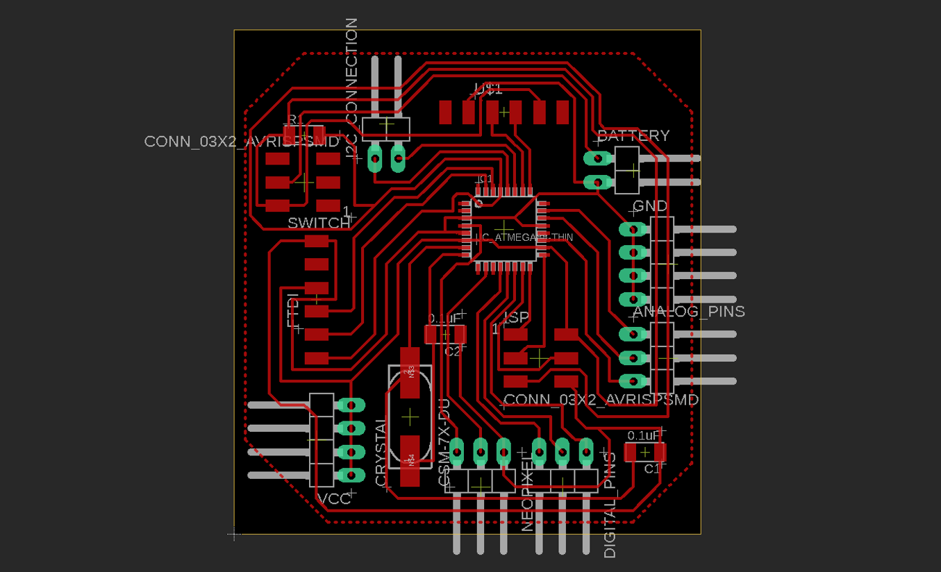
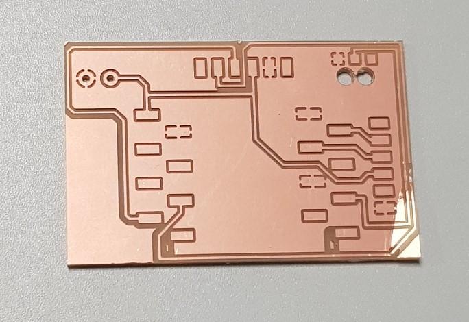
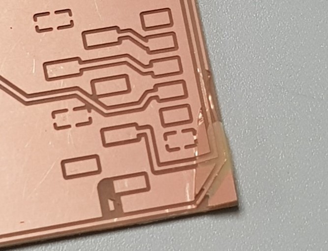
I used FlatCAM software to save the pcb. (steps of using FlatCAM are listed in Input Devices week)
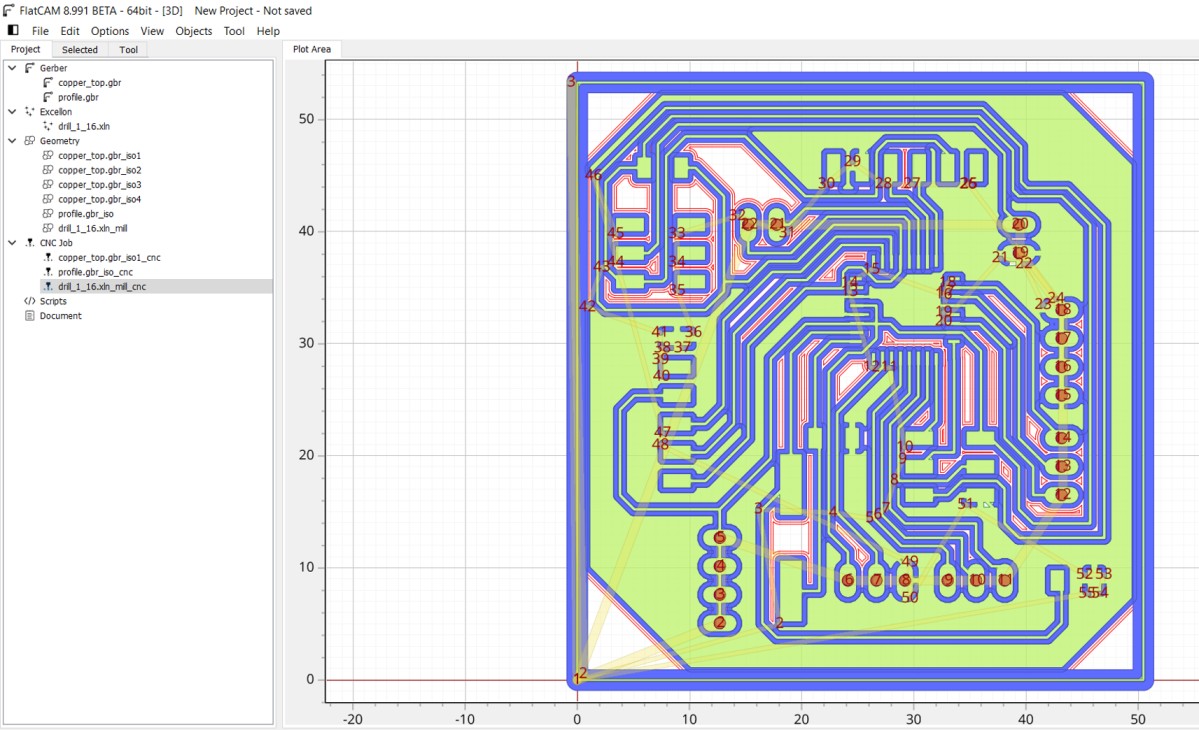
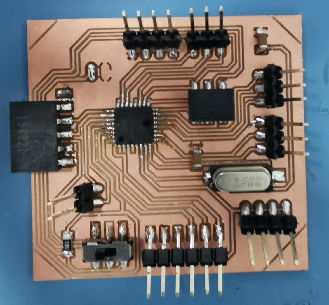
Then I took cnc files to Roland CNC Milling machine to mill the board then I soldered the components
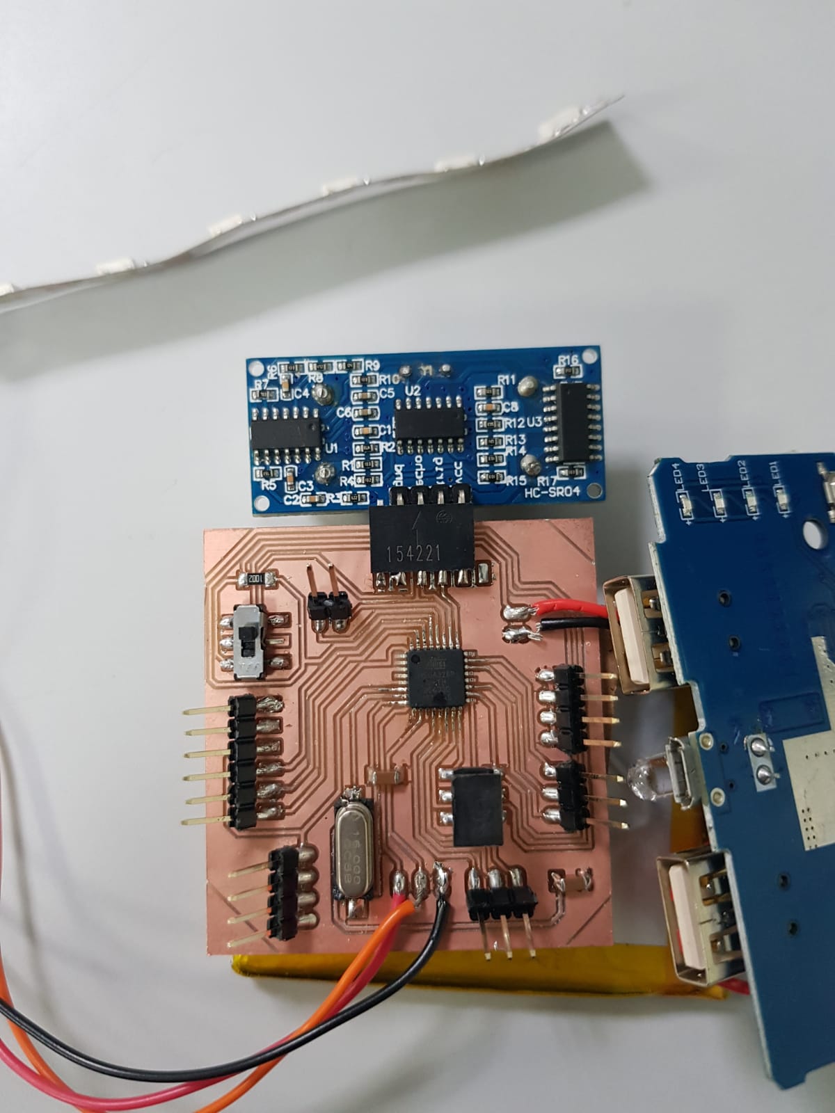
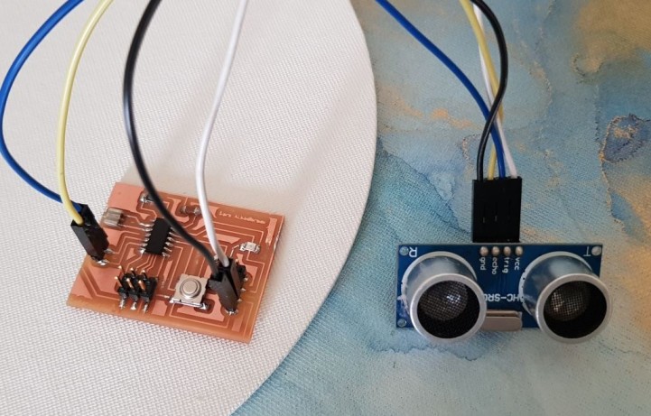
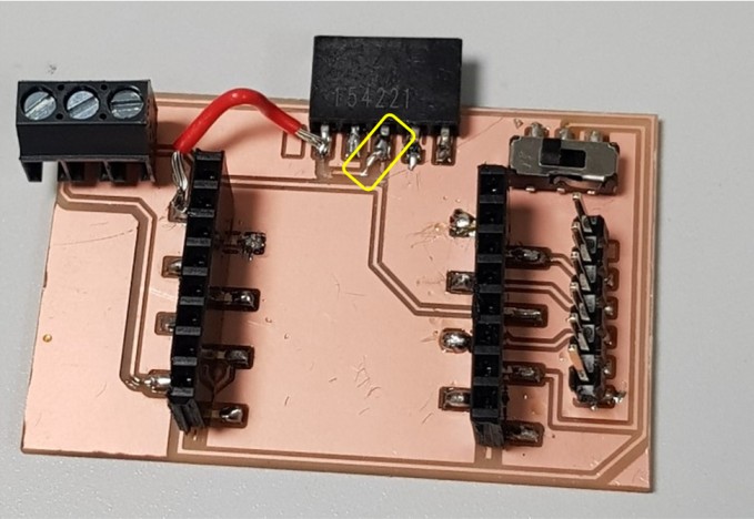
Here I connected the Ultrasonic Sensor, Neopixel LEDs and battery.
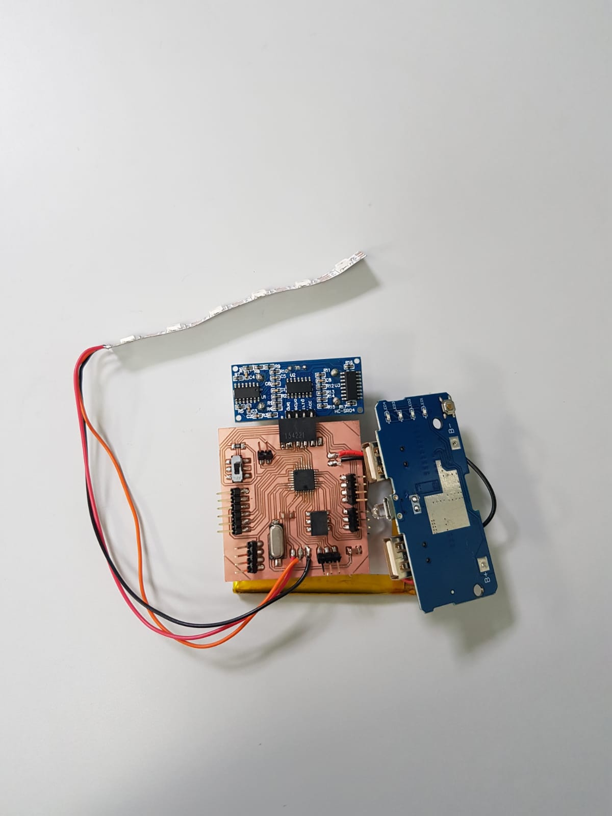
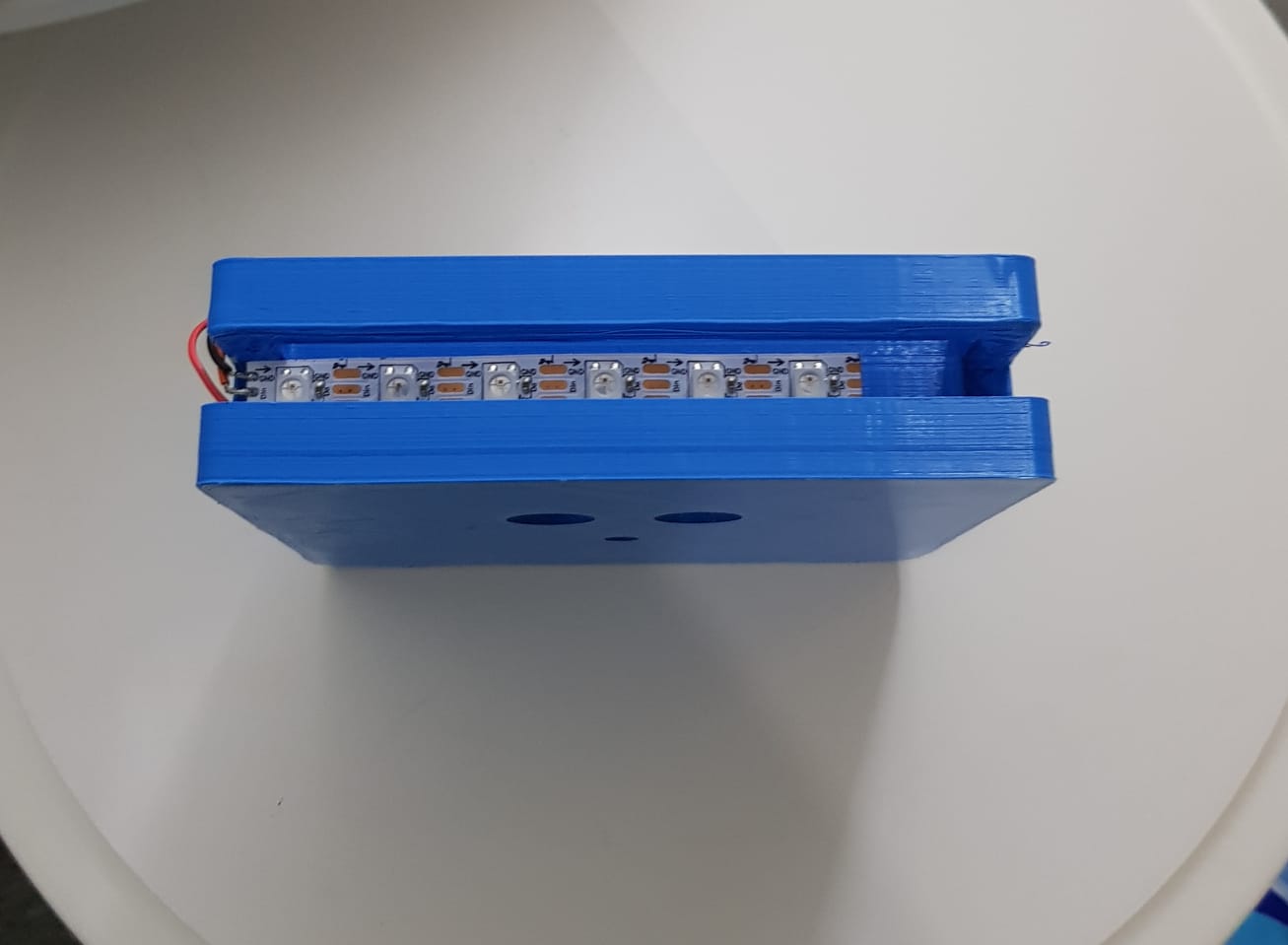
I placed the NeoPixel LEDs as shown in the following image to led up the acrylic board.
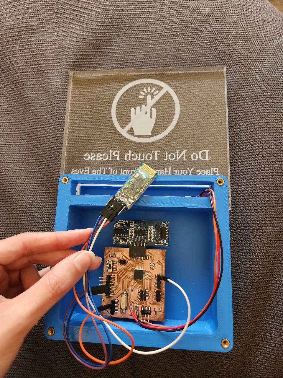
And I connected the bluetooth module with wires, vcc pin with orange wire, gnd pin with white wire, Tx is purple and Rx is blue. Tx to pin 1, Rx to pin 0 in arduino ide.
Testing
Ultrasonic Sensor has been tested in Input Devices week
Power
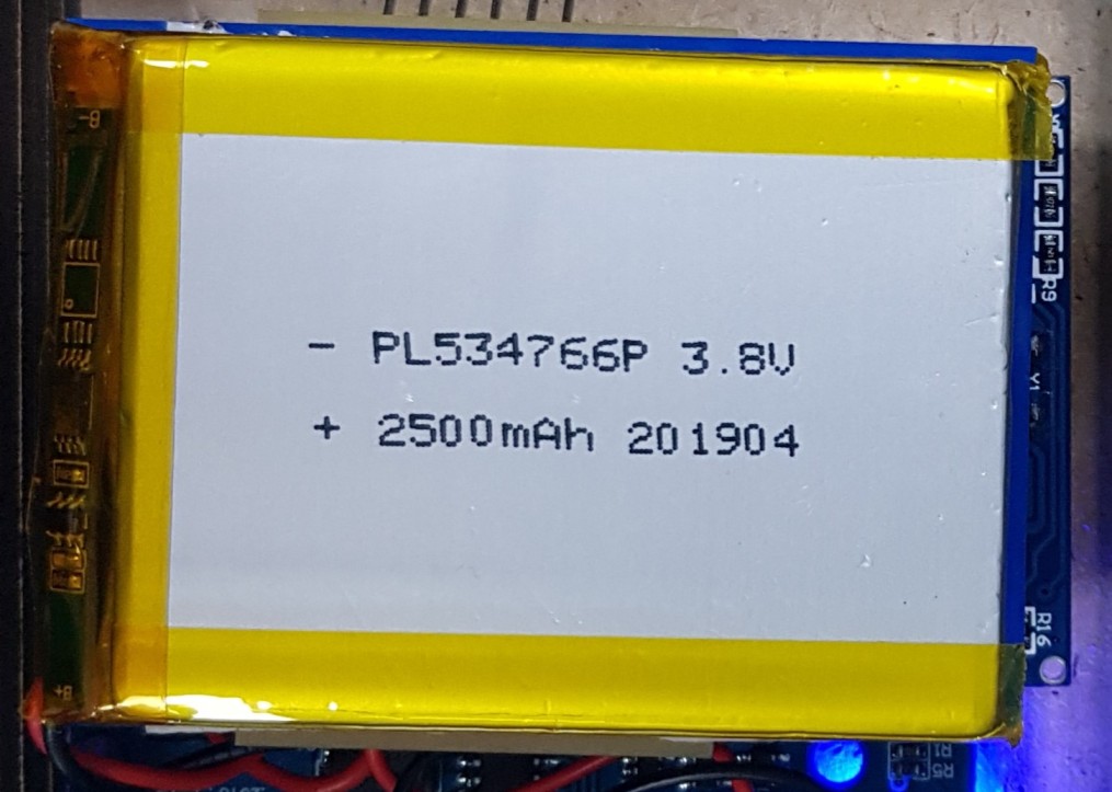
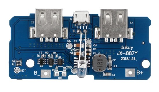
Device is powered by Lithium Ion Battery and a 5V boost module for Lithium Battery JX-887Y to convert the 3.8V coming from the battery to 5V to power the ESP32CAM, the Ultrasonic sensor and the Neopixel LEDs.
2500mAh Lithium Ion (LiPo) Battery
5V Boost Module JX-887Y
Programming
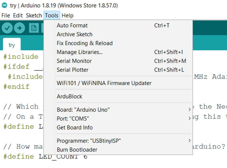
First I did Burn bootloader
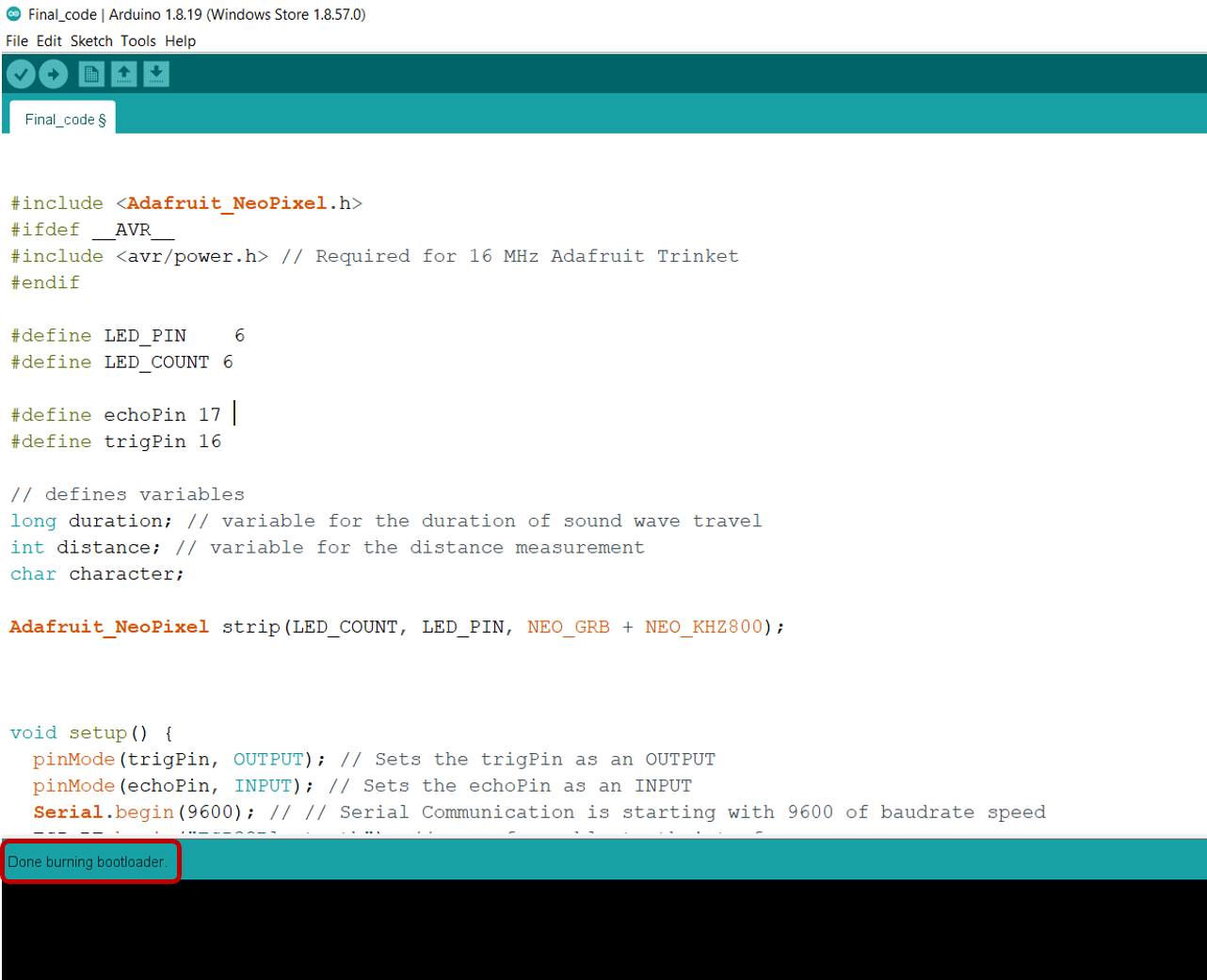
Then to test the board with the neopixel leds, I went to Libraries Manager to install Adafruit Neopixel to use the example code strandtest
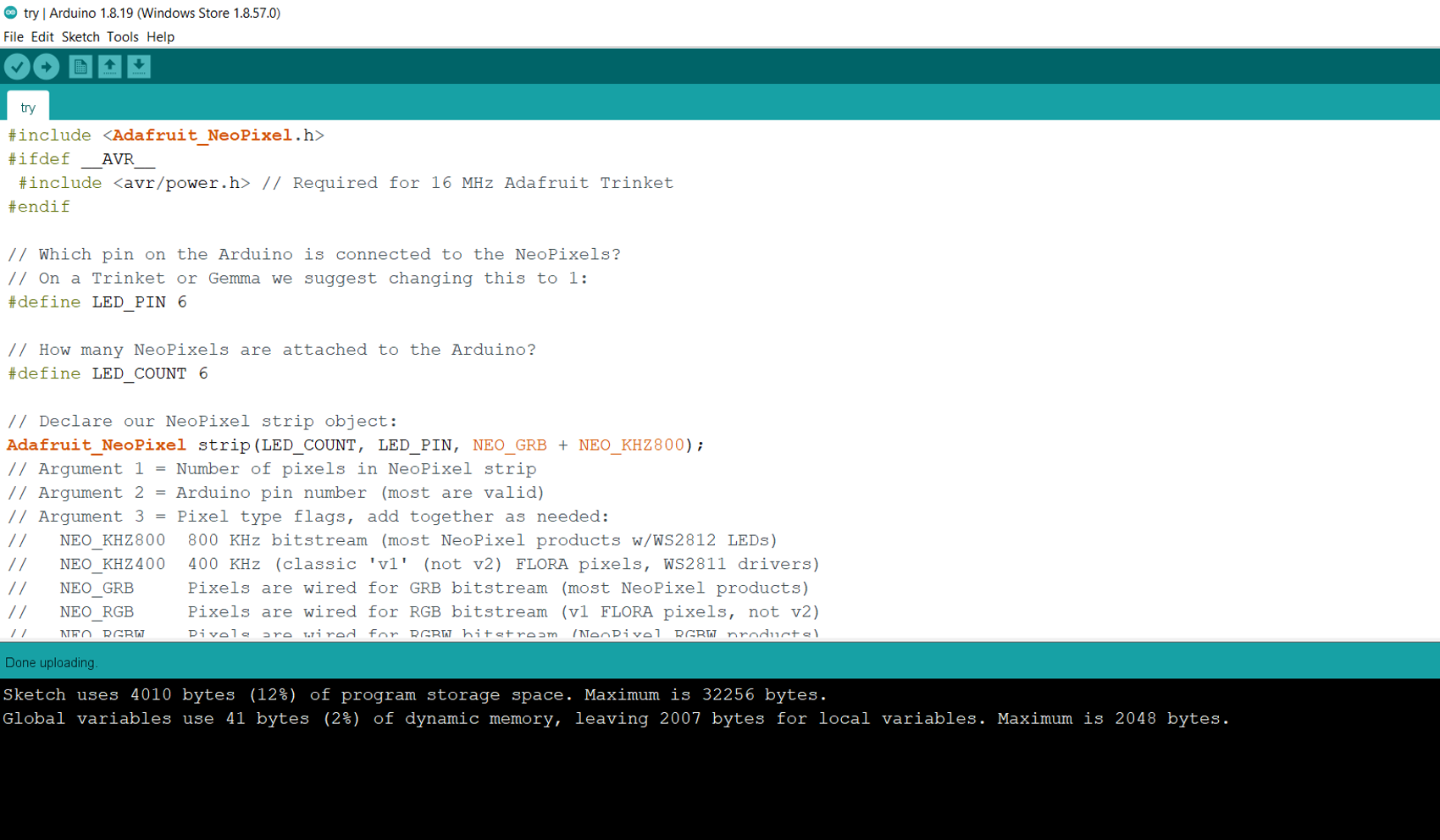
After that I updated the code by putting LED_PIN to 6 which is the pin where I cennected the neopixel to atmega board and LED_COUNT to 6 since I have six leds. I uploaded the code to my board using my ISPtiny and it worked successfully.
I updated the code again to make the neopixel light up with blue, and to connect the board with mit app through bluetooth
This is the link of the final code I used to control the ATmega328P microcontroller with the Ultrasonic sensor and the NeoPixel LEDs plus the Bluetooth communication between the PCB and the App.
The following video shows my board from two sides
Packaging
3D Design
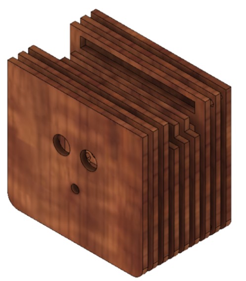
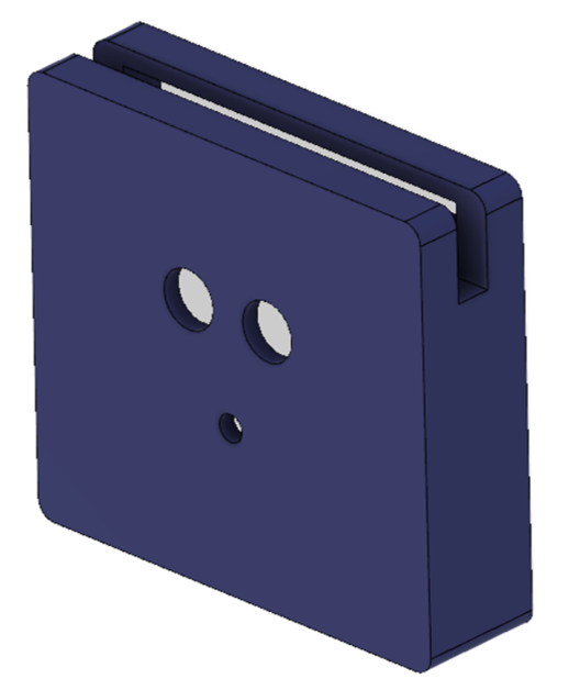
I used Autodesk Fusion360 to design the packaging of this unit. I saved the design in two ways, one to be cut by the Laser Cutting Machine and one to be printed by a 3D printer.
Design for Laser Cutting
Design for 3D Printing
3D Printing
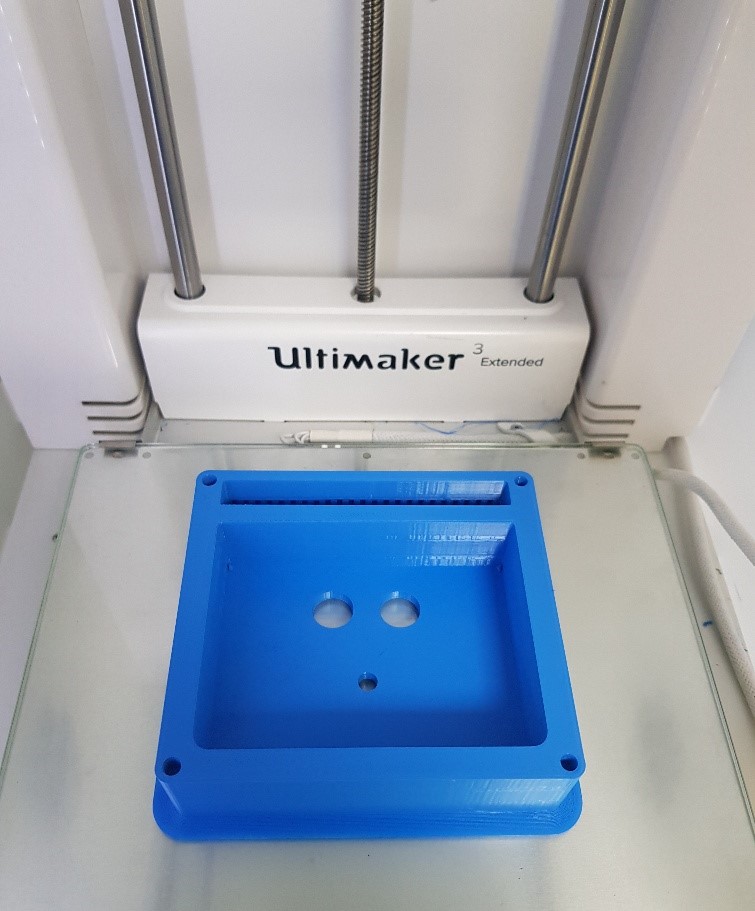
I used blue PLA/PHA material and printed in the Ultimaker Extended 3D printer
Settings:
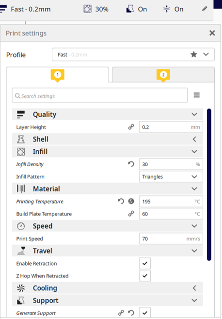
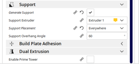
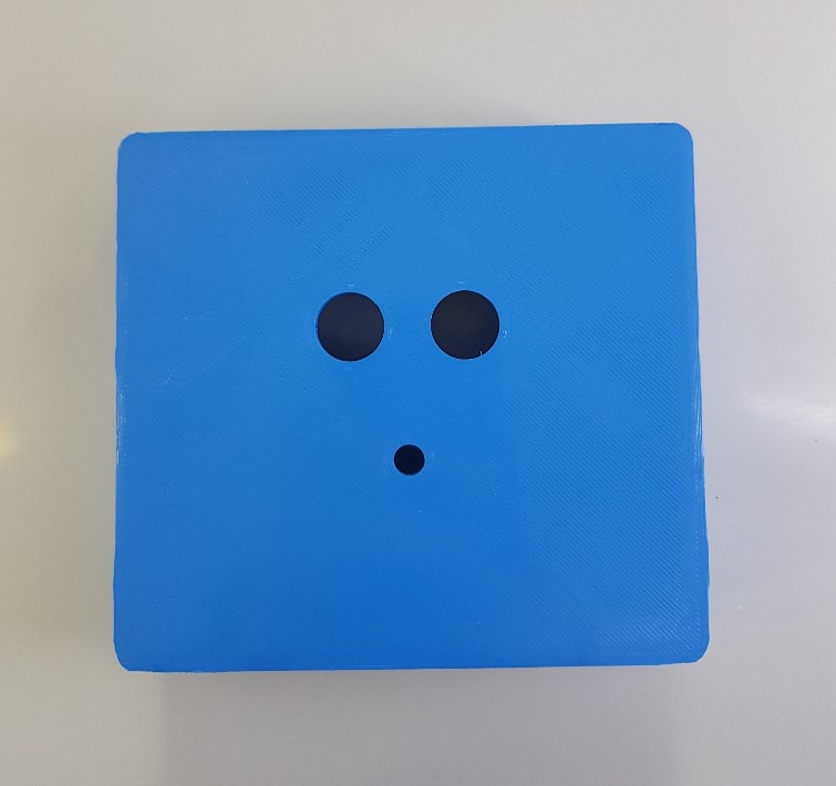
After printing
If you would like to learn more about 3D Printing, visit 3D Printing and Scanning page.
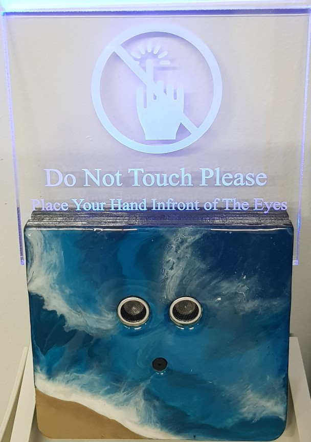
The following video shows how the project works after assymbling the 3D body with the electronics part and the top acrylic board.
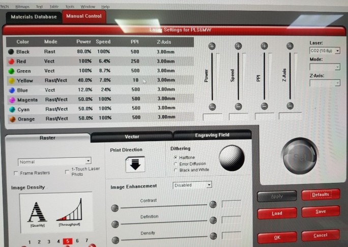
Laser Cutting
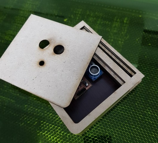
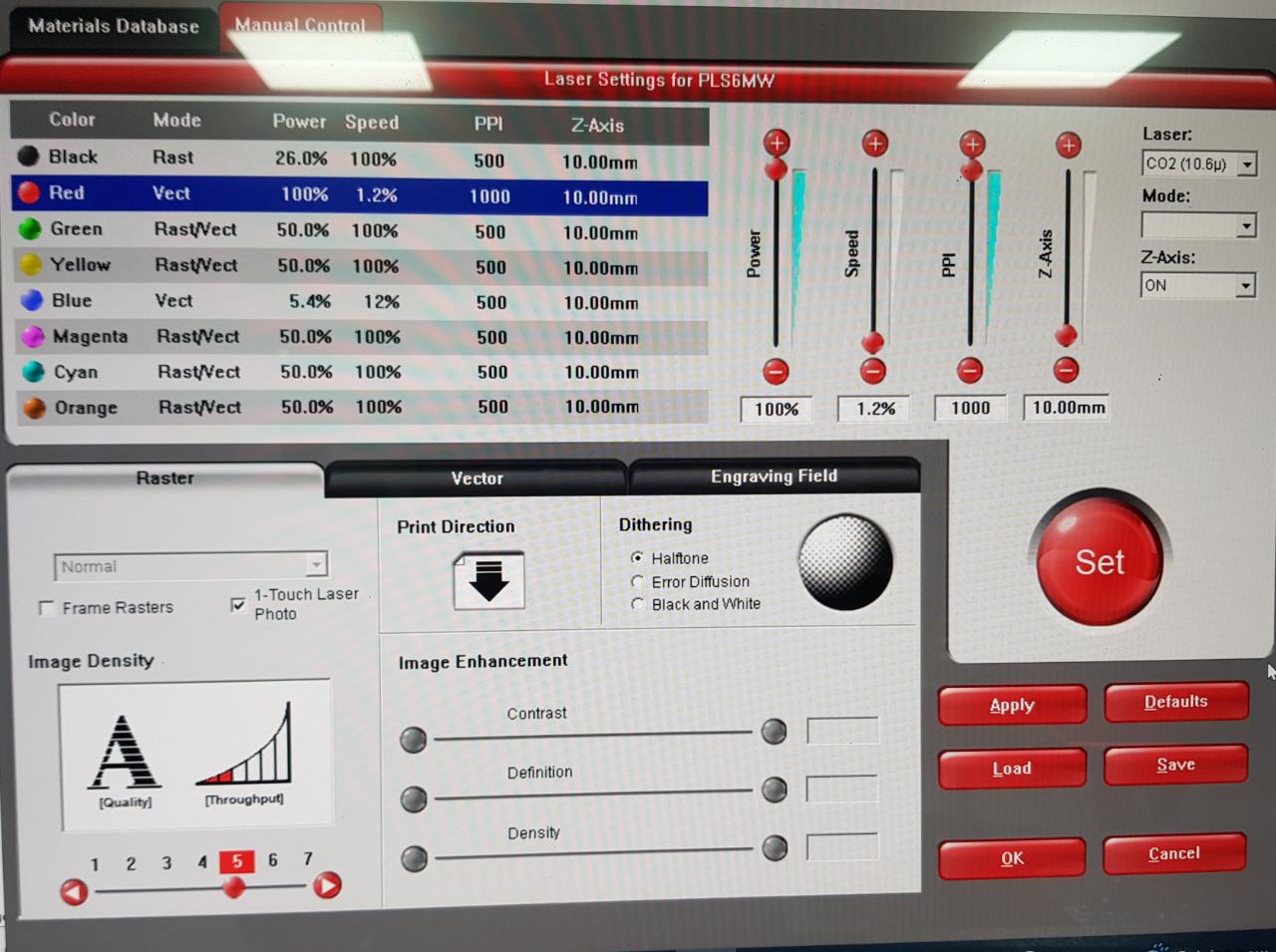
To make the packaging in different way, I did it by using laser cutting machine (Universal Laser Systems Machine). I used 3mm White Coated MDF material, I put the default settings of this material in our machine.
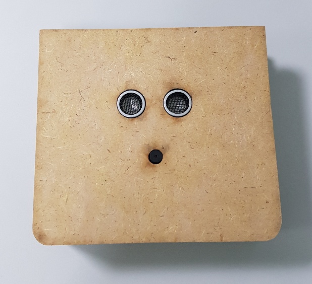
The result after cutting
If you would like to learn how to use laser cutting machines, visit Computer Controlled Cutting page.
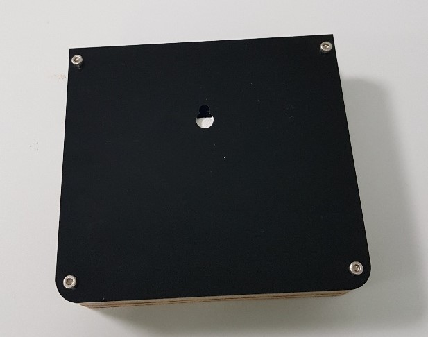
I covered it with a black 3mm acrylic
Acrylic Board
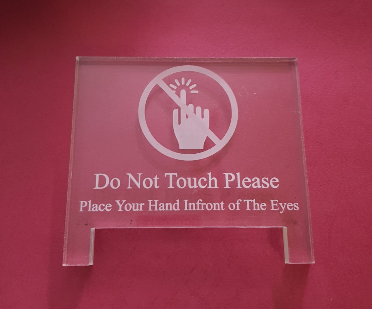
I also used the laser machine to cut the Acrylic board.
10mm transparent acrylic board.
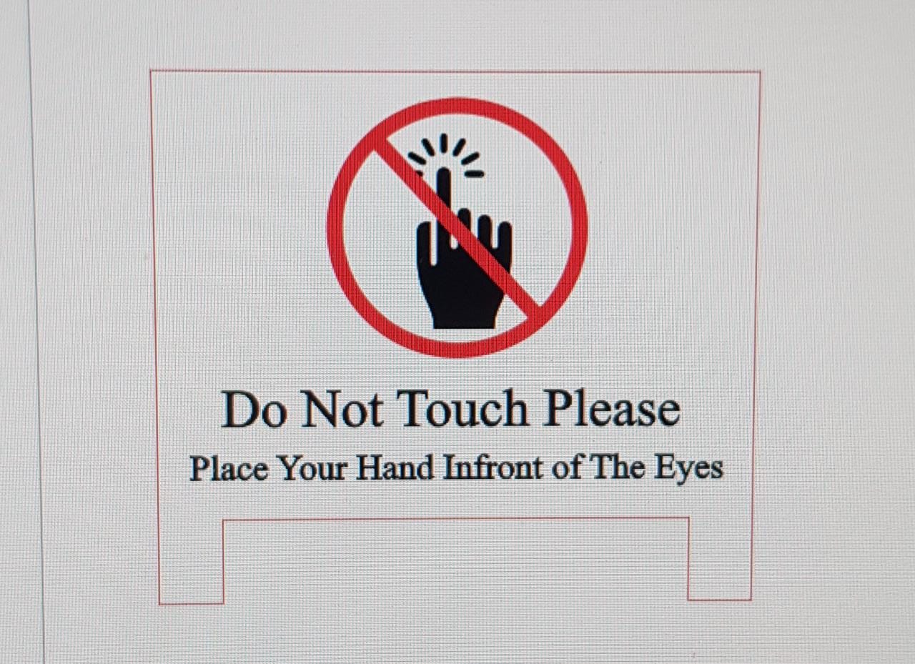
I designed the outline of the board in Fusion360 then I exported it as dxf file and I put it in CorelDraw software to put the sign and to write the statement on top of the board.
Then I opened the design in the laser machine software (steps of using the software and the laser machine are in Computer Controlled Cutting week), I cut the outline and I used engraving for the words written on the board and the sign.
Resin Art
I used resin to cover the cardboard
I used this tool I have at home to remove unwanted resin
And this how it looks finally
Wireless Communication
I used Wireless communication in this project by using Bluetooth in ATmega328P and Bluetooth in a smart phone and tablet.
In Interface and Application week I described how I used MIT APP Inventor to design the App that I used in an Android tablet. With the App I connected Bluetooth in the tablet with my smart doorbell.
Problems Faced:
I broke the first board
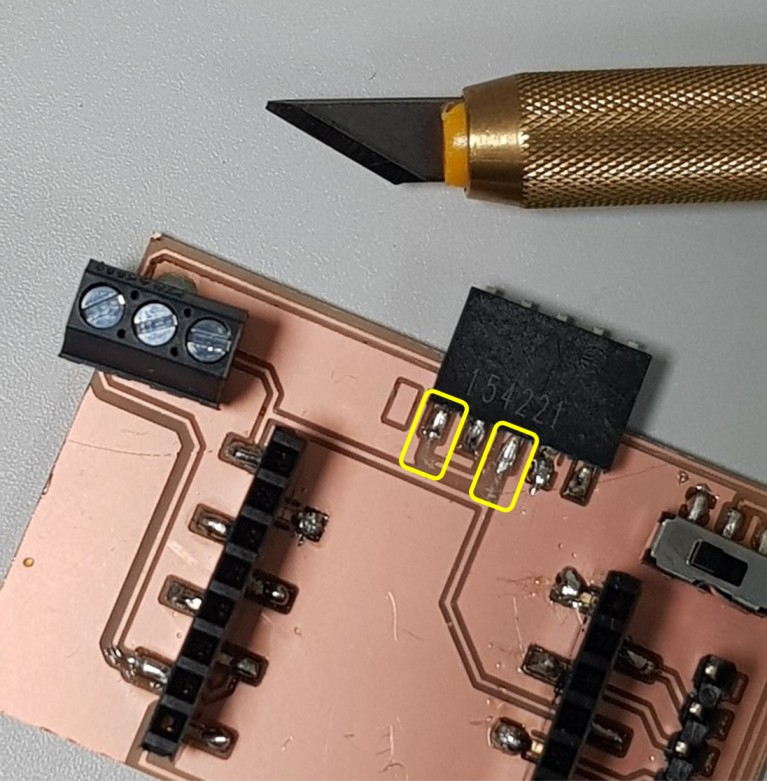
Then I milled another board. I realized here that I switched between VCC and ECO pins. I fixed that by cutting the traces and solder it again by using wire for the vcc and I soldered the eco trace directly.
After that I found another mistake. I reversed the right side of the ESP32CAM header which caused short circuit between VCC and GND. Finally I fixed the design and I milled the board agian.
Troubleshooting
ESP32CAM
- While connecting the esp32 with the pc through the FTDI cabel, the esp becomes very hot, which means that there could be a short circuit either in the board or in the esp32cam. I tested the board alone by using the multimeter and its fine there is no short circuit. Then I tested the esp32cam alone and its fine there is no short circuit. After that I checked them together by connecting the esp32cam with the board and using the multimeter to check if there is a short circuit between the vcc and gnd. Yes, there is a short circuit now.
The problem is that the right side of the esp32cam is fliped in the board and I forget to connect the vcc pin at that side.
I fixed the circuit board from the schematic and I milled a new PCB then I soldered the components agian in the new board.
- I did a totaly new PCB for my project and I used ATmega 328P microcontroller instead of ESP32CAM.
Files list:
| Packaging design | Fusion360 File |
| Packaging design | STL File |
| Acrylic board design | Fusion360 File |
| Acrylic board Outline | DXF File |
| PCB board design | Eagle File |
| Schematic design | Eagle File |
| Final Programming Code | Arduino IDE File |
Close Project