
Input Devices
Group assignment:
- Probe an input device(s)'s analog and digital signals - Document your work (in a group or individually)
Individual assignment:
- Measure something: add a sensor to a microcontroller board that you have designed and read it.
Machine used:
Milling machine
Software used:
Autodesk Eagle
Arduino IDE
Individual Assignment:
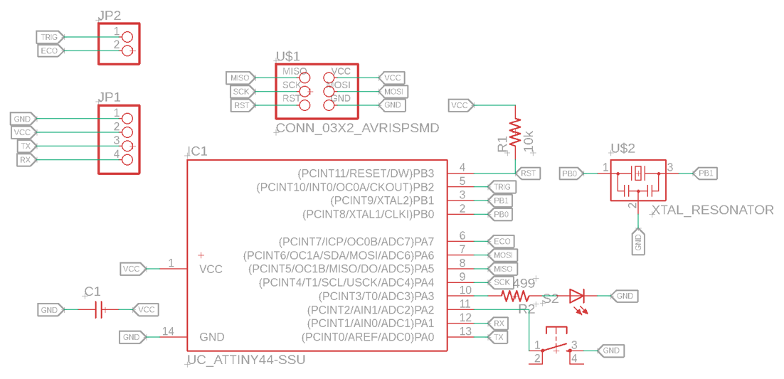
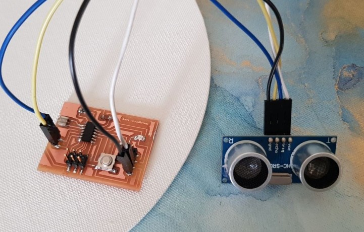
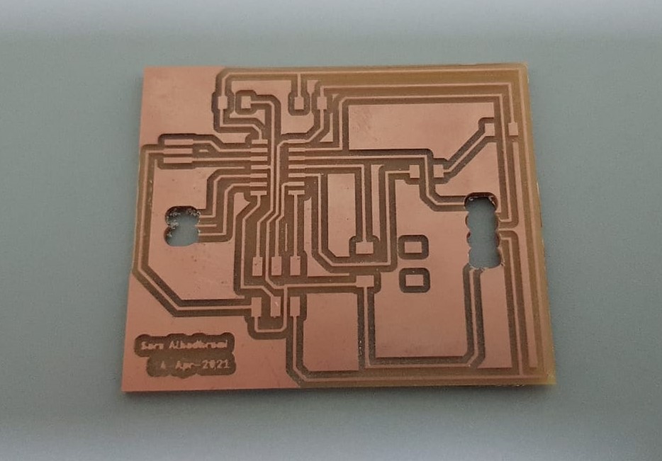
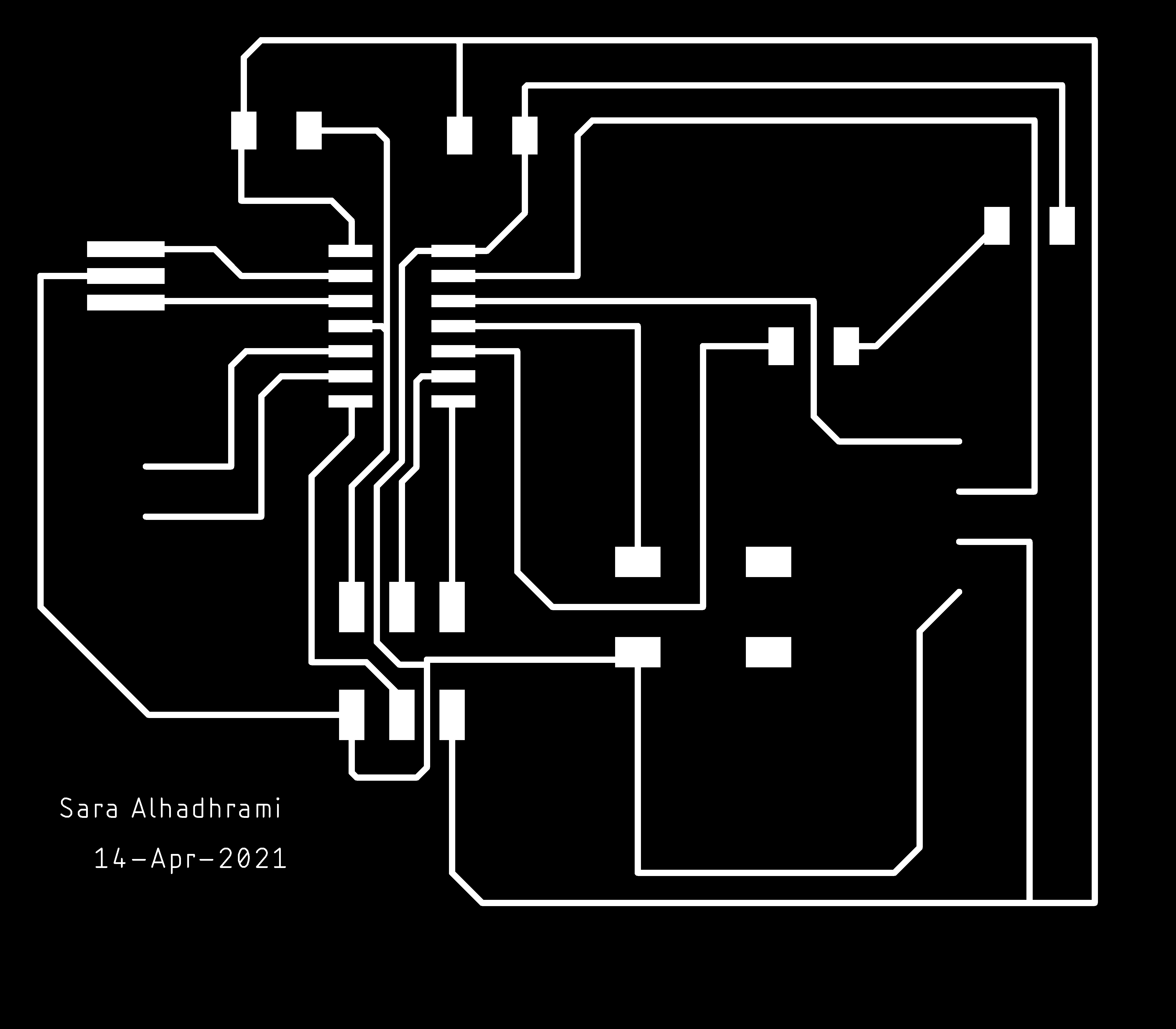
In this week I modified the PCB I designed in Electronics Design week by adding a six pins header to use it for connecting the input device which is the Ultrasonic sensor.
The circuit was consists of two LEDs and one button, I removed one of the LEDs and I added 6 pin headers. I conected all the free pins in the microcontroller ATtiny44 with the header.
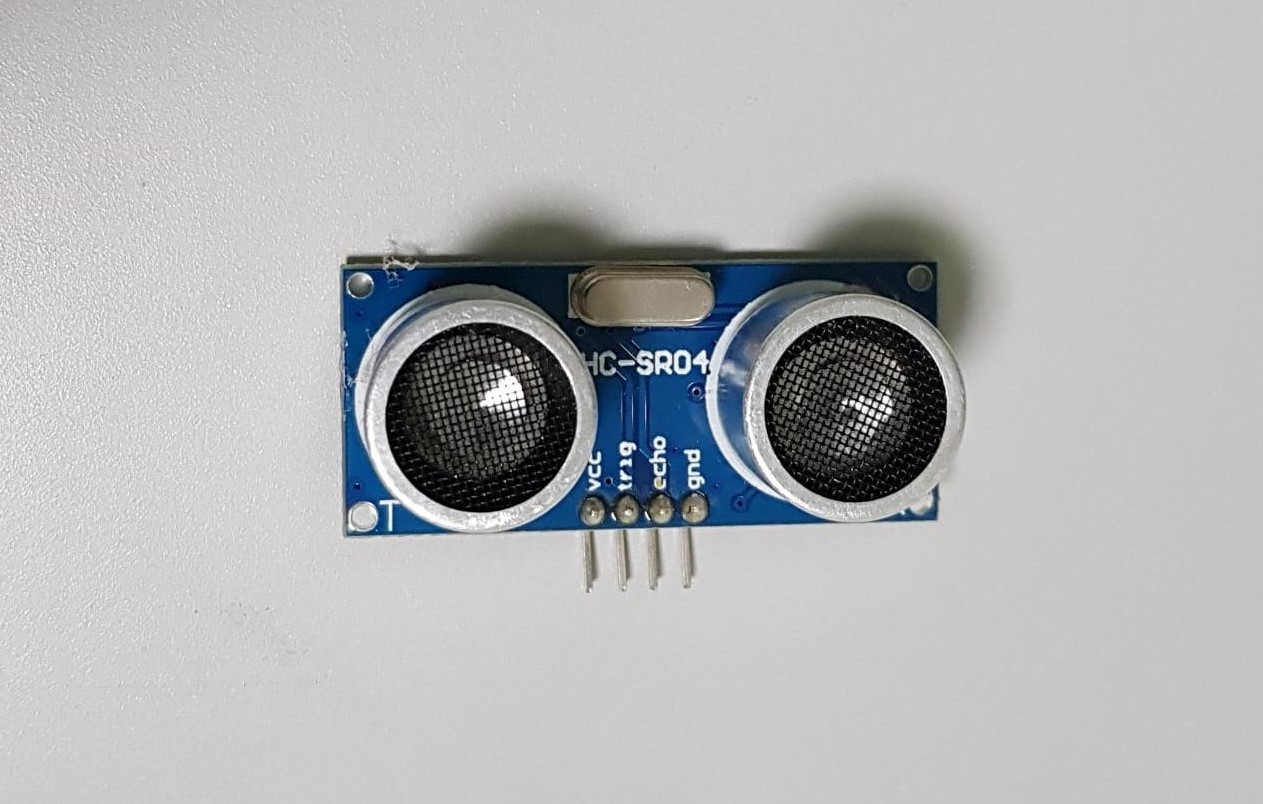
I chose to use Ultrasonic sensor because I need it for my final project. I will use this sensor to sense the existace of objects and I will program it to sence objects if they are closer than a specific distance.
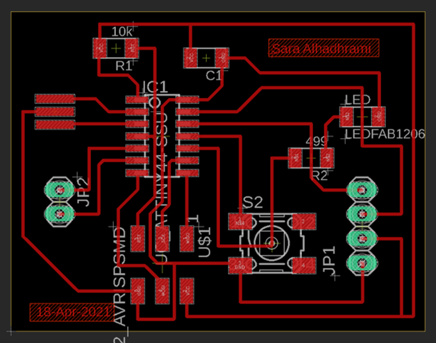
I used FlatCAM software to save the PCB design to put it in the milling machine.
Before saving the design, I went to Display Setting to set the scale of the desktop to 100%
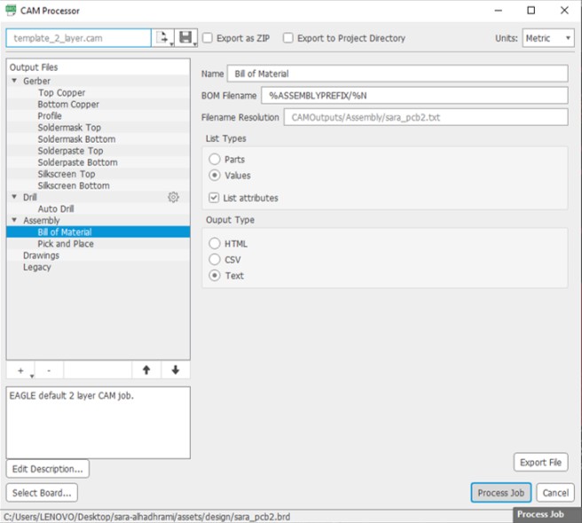
To put the design in FlatCAM, I clicked on Manufacturing >> CAM >> Process Job then I save the file.
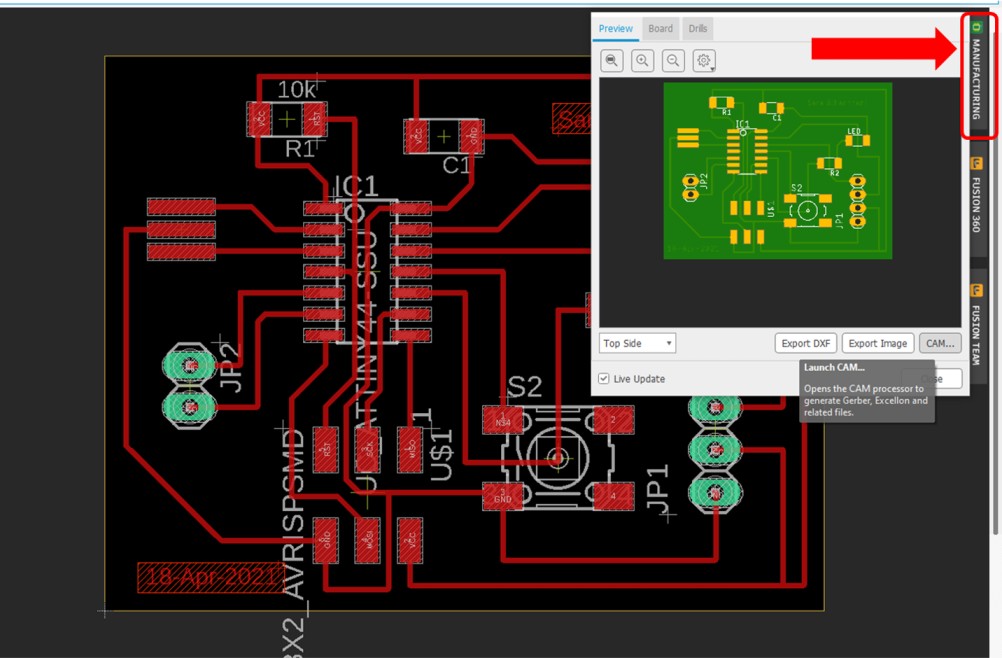
After that, I opened FlatCAM and I did the following steps.
Steps in FlatCAM:
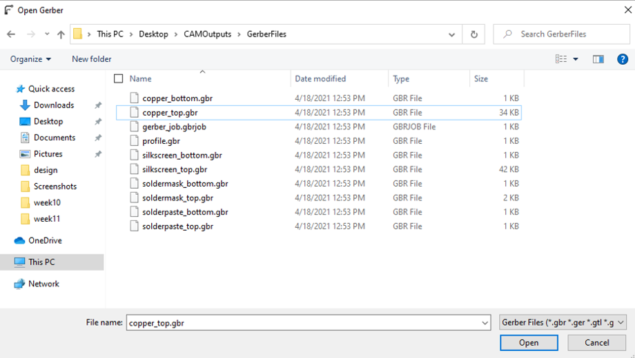
1. Open >> Open Gerber >> GerberFiles >> copper_top.gbr
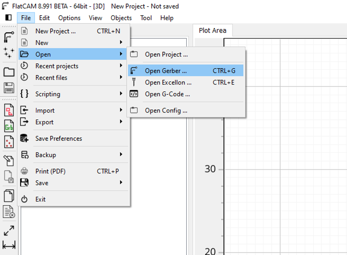
2. Open >> Open Gerber >> GerberFiles >> profile.gbr
3. Open >> Open Excellon >> DrillFiles >> drill_1_16.xln
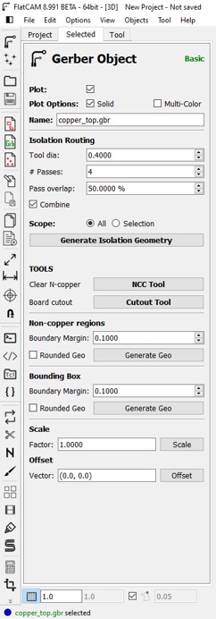
4. Project >> Geber >> Double click on copper_top.gbr >> modify the following
(Tool dia: 0.4) , (# passes: 4) , (Pass overlap: 50%)
Then click on Generate Isolation Geometry
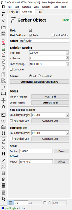
5. Project >> Geber >> Double click on profile.gbr >> modify the following
(Tool dia: 0.8) , (# passes: 1) , (Pass overlap: 10%)
Then click on Generate Isolation Geometry
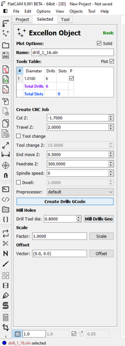
6. Project >> Excellon >> Double click on drill.xln >> modify the following
(Cut Z: -1.7) , (Travel Z: 2) , (End move Z: 0.5)
Then click on Mill Drills Geometry
- After these six stps you end having three geometry files
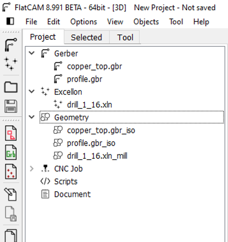
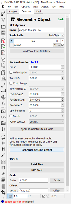
7. Project >> Geometry >> Double click on copper_top.gbr_iso >> modify the following
(Cut Z: -0.1) , (Travel Z: 2) , (End move Z: 80) , (Feedrate X-Y: 240) , (Feedrate Z: 60)
Then click on Generate CNCJob object
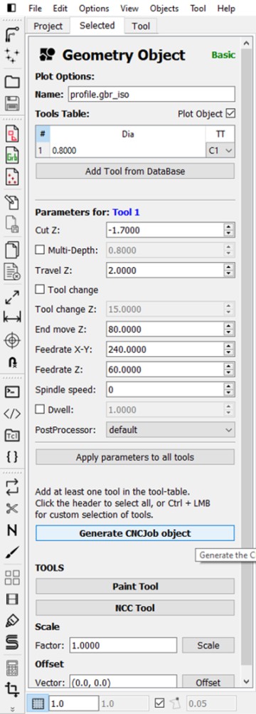
8. Project >> Geometry >> Double click on profile.gbr_iso >> modify the following
(Cut Z: -1.7) , (Travel Z: 2) , (End move Z: 80) , (Feedrate X-Y: 240) , (Feedrate Z: 60)
Then click on Generate CNCJob object
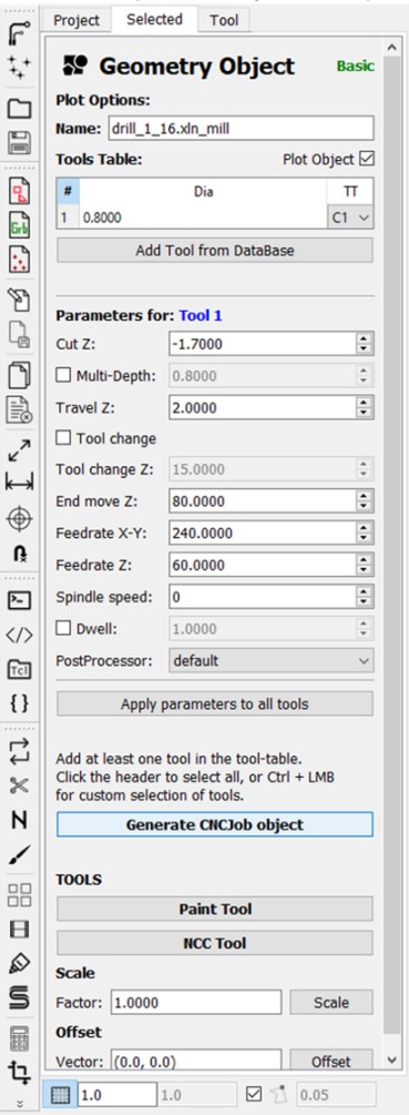
9. Project >> Geometry >> Double click on drill_1_16.xln_mill >> modify the following
(Cut Z: -1.7) , (Travel Z: 2) , (End move Z: 80) , (Feedrate X-Y: 240) , (Feedrate Z: 60)
Then click on Generate CNCJob object
- After these steps you end up having three cnc files.
10. Double click on each cnc file >> click on Save CNC Code
- Finally, take these file to a CNC Milling Macine.
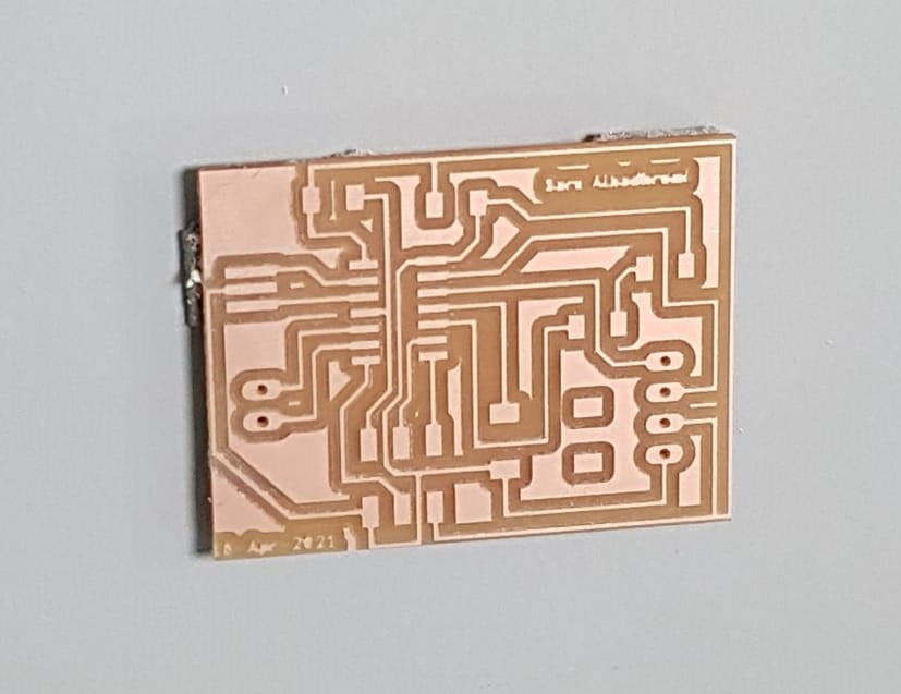
After milling
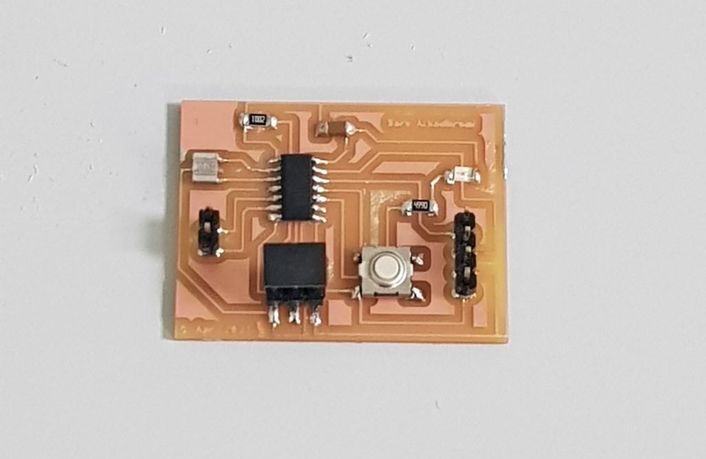
After soldering
The followimg image shows the Ultrasonic sensor I will use.
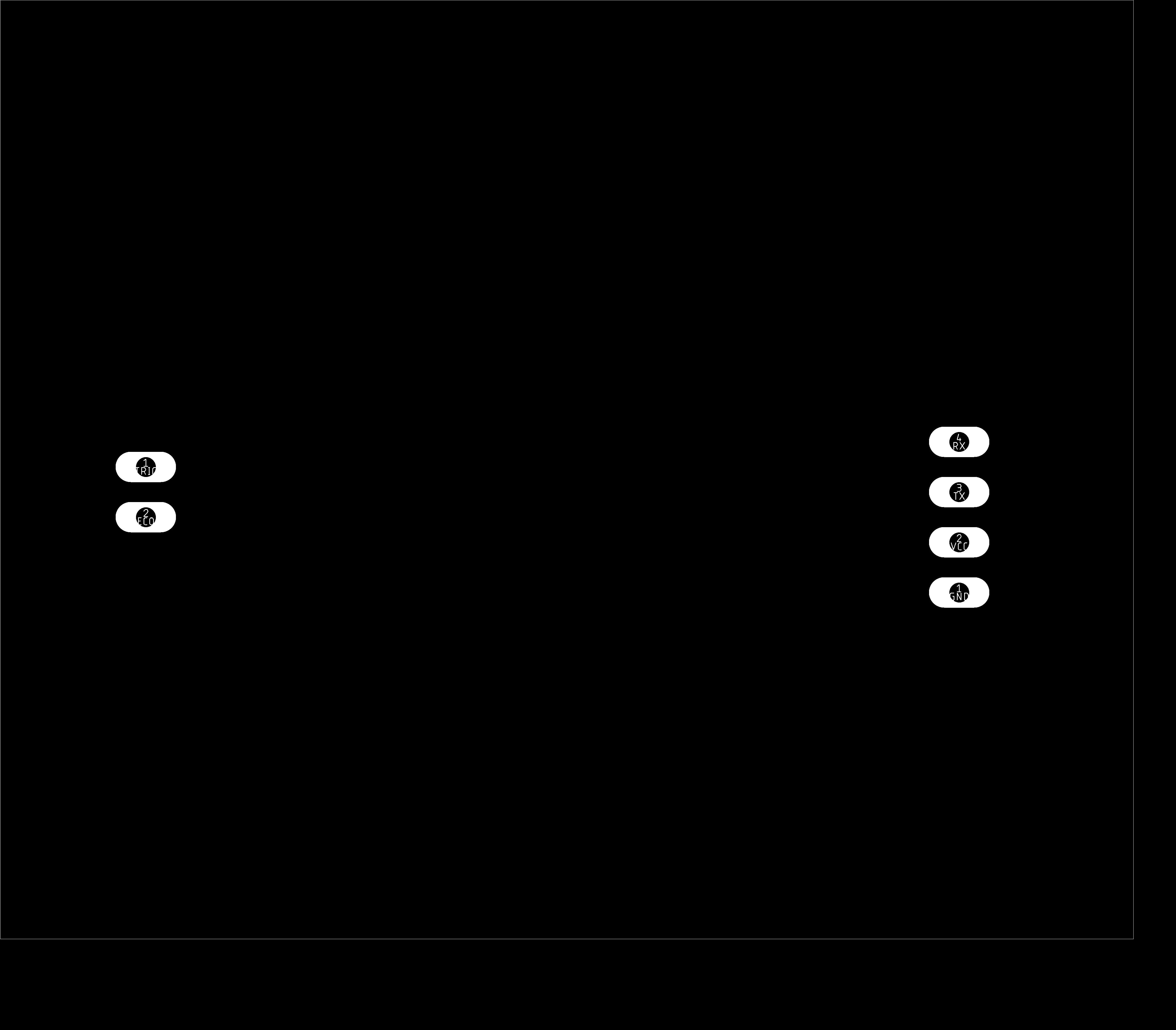
I used four jumper wires to connect the sensor with the board. VCC and GND in the sensor connected with VCC and GND in the board. Trig pin in the sensor is connected with pin PB2 in the microcontroller ATtiny44 and Echo connected with pin PA7 in ATtiny44.
Programming:
I will be using Arduino IDE software to program the sensor.
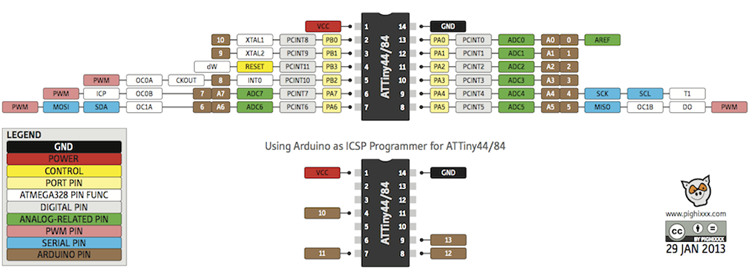
The following image shows the pinout of ATTiny44 and Arduino pins. The numbers in brown boxes are associated with Arduino pins and I will be using them in programming. For example, if the Trig pin in the sensor is connected with pin PB2 in ATTiny44, it means that it is connected to pin 8 in Arduino and I will refer to Trig pin in Arduino IDE by the number 8.
Now I need to use an FTDI cabel to see the readings of the sensor on the serial monitor.
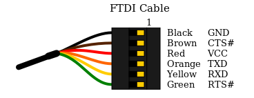
I used 4 more jumper wires to connect the FTDI cabel with the board. I connected TX in the ftdi cabel with RX in the board and RX in the cabel with TX in the board. Also VCC is connected with VCC and GND with GND.
Ultrasonic sensor measures the distance of objects as shown in the following video.
Here is the code I used:
#include < SoftwareSerial.h >
#define TX 0
#define RX 1
SoftwareSerial serial(RX,TX);
#define echoPin 7
#define trigPin 8
const int ledPin = 3;
long duration;
long distance;
void setup() {
pinMode(trigPin, OUTPUT); // Sets the trigPin as an OUTPUT
pinMode(echoPin, INPUT); // Sets the echoPin as an INPUT
pinMode(ledPin,OUTPUT);
serial.begin(9600); // // Serial Communication is starting with 9600 of baudrate speed
serial.println("Ultrasonic Sensor HC-SR04 Test"); // print some text in Serial Monitor
serial.println("with Arduino UNO R3");
}
void loop() {
// Clears the trigPin condition
digitalWrite(trigPin, LOW);
delayMicroseconds(2);
// Sets the trigPin HIGH (ACTIVE) for 10 microseconds
digitalWrite(trigPin, HIGH);
delayMicroseconds(10);
digitalWrite(trigPin, LOW);
// Reads the echoPin, returns the sound wave travel time in microseconds
duration = pulseIn(echoPin, HIGH);
// Calculating the distance
distance = duration * 0.034 / 2;
serial.print("Distance: ");
serial.print(distance);
serial.println(" cm"); }
Another test has been done to test the ultrasonic sensor. I used the same code and I added an if statement to test if the sensor can write the word good in the serial monitor when it detects bodies that are closer than 10cm.
Uploading code is done by USBtinyISP, then I remove it and I connect FTDI cabel to open the serial monitor.
Group Assignment:
Group Page LinkUltrasonic Distance Sensor
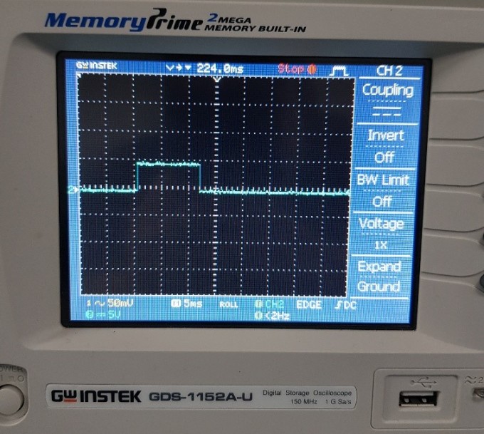
I used the oscilloscope to see the signals of Eco pin in the ultrasonic sensor.
The following video shows the 5V supplied to the board and the output signals from ECO pin. Signals of Trig pin (Input) are represented as impulses.
Echo pulses at 1 second time interval width.
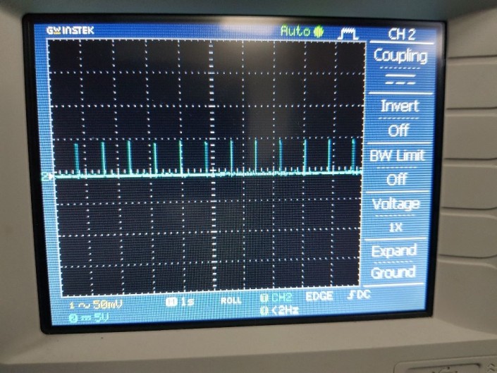
Echo pulses at 5ms time interval width.
Problems I faced:
Problem (1) :I used Fab Module to saved the traces, outline and holes as rml file but I had a mistake while saving holes. Holes are used for headers of through hole type which need a hole to insert pins inside it. And around each hole should be a circle of copper as shown in the following image.
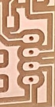
When I converted holes to rml file I selected the outline of the circles around the holes and I saved it to be milled by using the 1/32 milling bit which is used for cutiing outlines. And the result was as follows.
Holes in Fab Modules: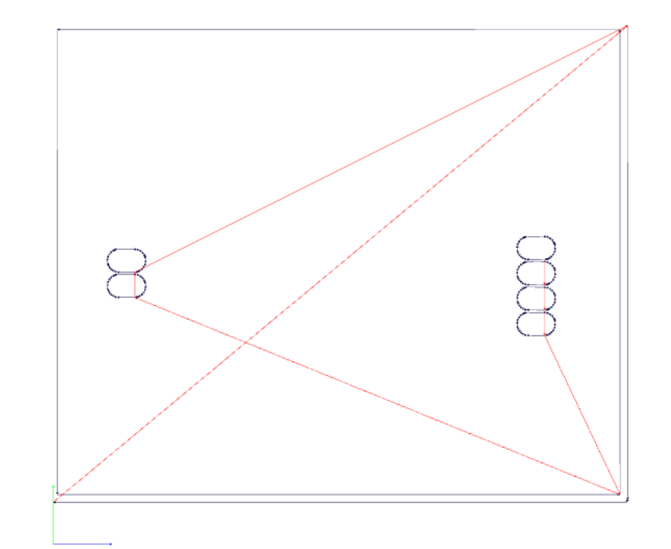
Result:
I used FlatCAM software because its easier than Fab Modules in converting holes to rml format.
Problem (2) :
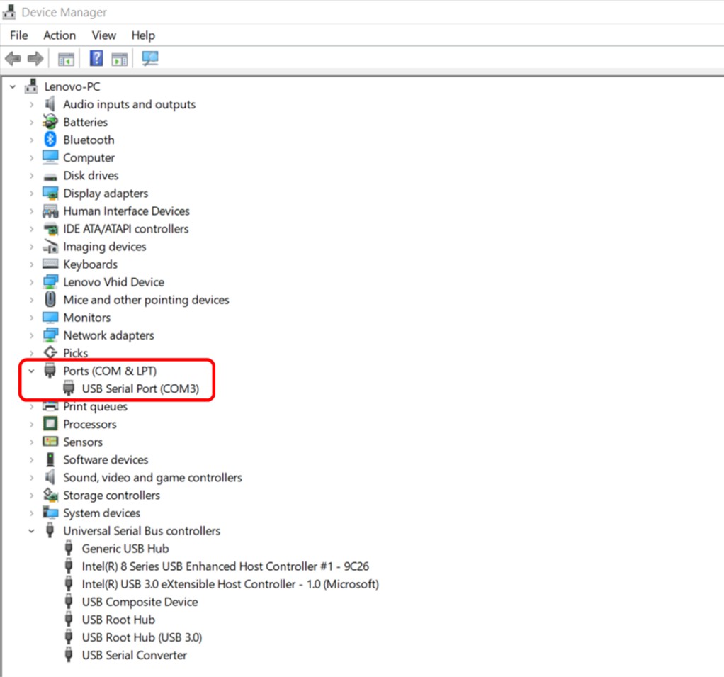
I had a problem while inserting the FTDI cable in my PC that I can't select the port in Arduino IDE. And I found that when I insert the cable there was a sound coming on but in the Device Manager it doesn't appear that the cable in connected to my PC.
Therefore, I installed FTDI drivers that solved this problem.
Files list:
| Board | Eagle File |
| Schematic | Eagle File |
| Sensor code 1 | Arduino IDE File |
| Sensor code (IF Statement) | Arduino IDE File |
| Source code | C File |
| Traces | png File |
| Outline | png File |
Tutorial Link:
- Ultrasonic Sensor Tutorial Link
Close Project