
Electronics Design
Group assignment:
- - Use the test equipment in your lab to observe the operation of a
microcontroller circuit board (in minimum, check operating voltage on the board with multimeter or
voltmeter and use oscilloscope to check noise of operating voltage and interpret a data signal)
Individual assignment:
- - Redraw one of the echo hello-world boards or something equivalent, add (at least) a button and LED (with current-limiting resistor) or equivalent input and output, check the design rules, make it, test it.
Software used in this week:
- 1. Autodesk Eagle
- 2. VPanel for SRM-20
Individual Assignment
- In this week, I learned using the software Eagle to design Printed Circuit Board (PCB).
- Designing PCBs started by designing the Circuit schematic then converting it to an Electronic Board.
Below I'm describing the steps I did to design my first PCB:
- First, I downloaded the software Autodesk Eagle
- 1. ATtiny44 microcontroller
- 2. Two LEDs
- 3. Button
- 4. Two 499 Ohm resistors (limiting current resistors)
- 5. One 10K Ohm resistor
- 6. One 1μF Capacitor
- 7. Resonator
- 8. ISP header
- 1. Set the display scale in your PC to 100%.
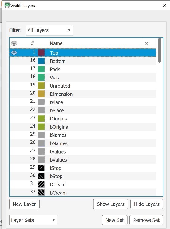
Right click on your Desktop >> Display Settings >> Scale and Layout >> Change size to 100% - 2. Hide all layers except the top layer
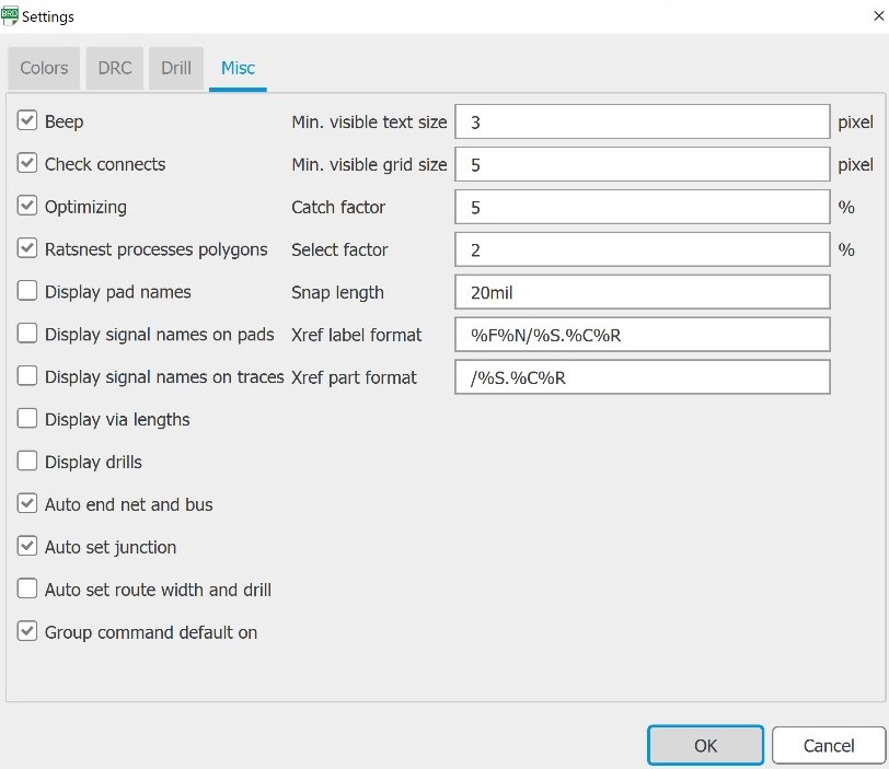
Go to Layer Settings >> Select all layers and click Hide >> Select Top layer and click Show - 3. Go to Options >> Set >> un-check all lines with display
- 4. Go to File >> Export image >> Click on Monochrome box >> Set Resolution to 2000 >> Ok
Here is the result. A png image - 5. For the outline, I opened the previous image in Paint then I drew a white square to make the outline of the board and I save it as png image
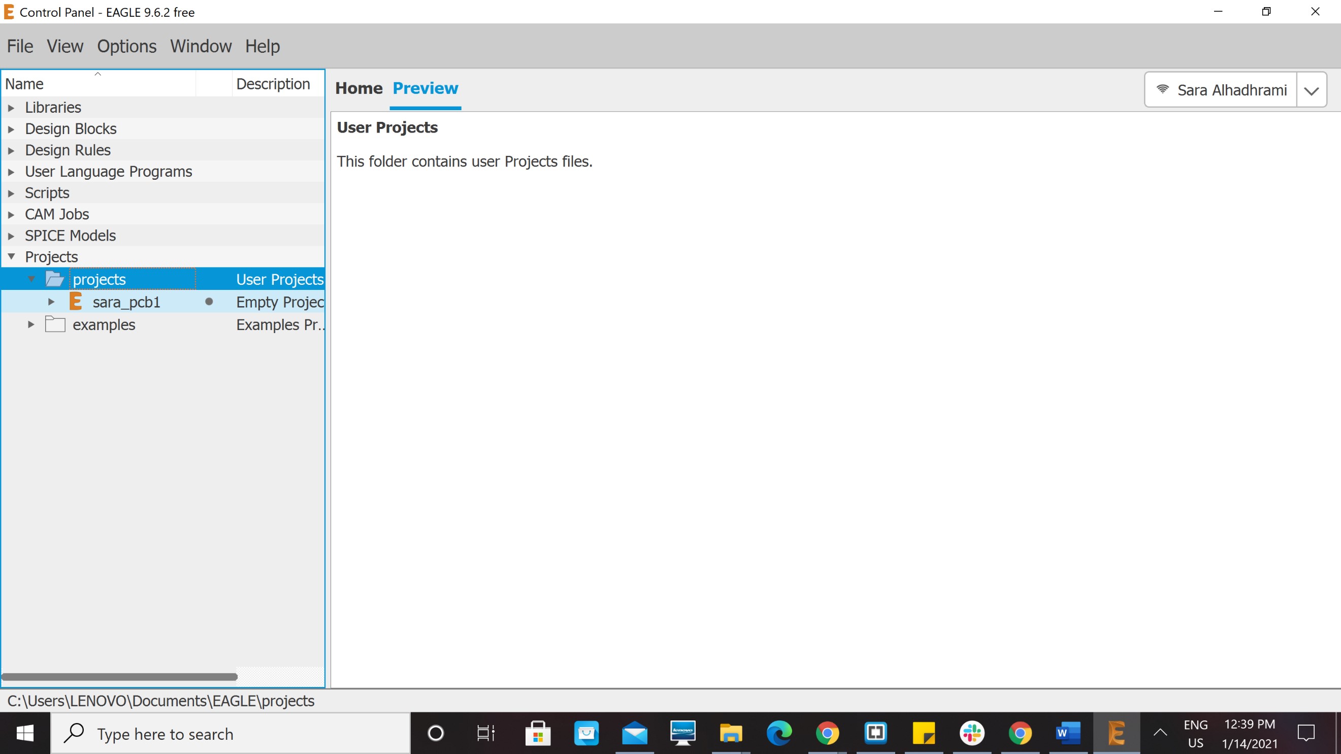
After that, I created a new project. Go to Prejects >> right click >> New Project. I name it sara_pcb1.

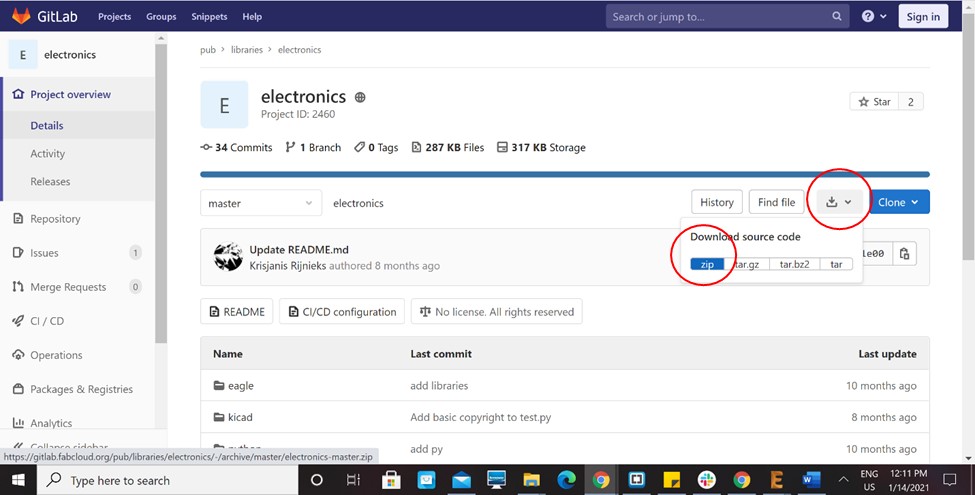
Then I downloaded the Fablab Eagle Library. Which includes a bunch of electronic components that we can use in designing PCBs.
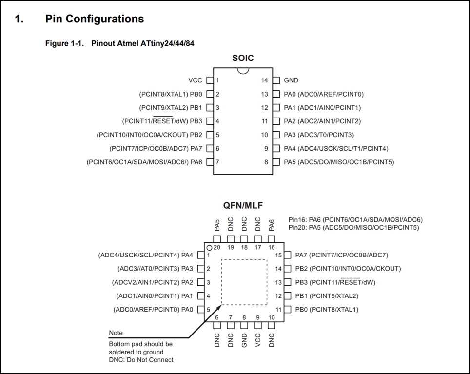
After that, I started reading the Datasheet of the microcontroller I will use "ATtiny44".
The folowing picture shows the pin configuration of ATtiny44. I used it to find power and ground pins. Also, digital and analog input and output pins, in addition to transmit Tx and receive Rx pins.
Components I used:
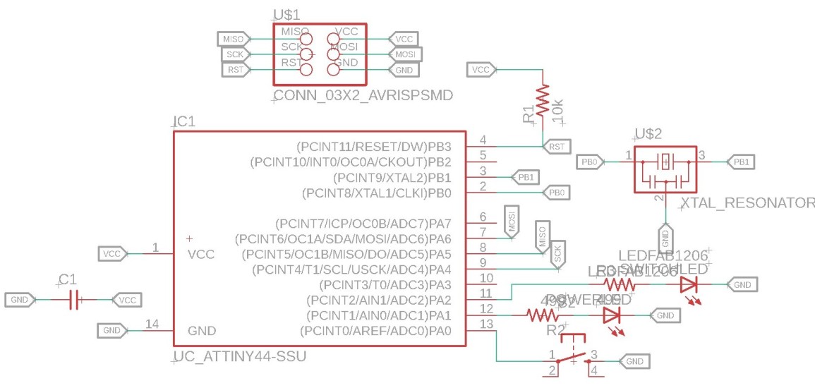
I designed a PCB that includes two LEDs. One of them will light ON immidiatly as the microcontroller is powered. I used it as a power LED to check if power reaches the microcontrller or not. The other LED will be controlled by the button. The microcontroller reads from the button, if it is ON the LED will be ON, and if the button is OFF, the LED will be OFF.
I put 1μF capacitor between VCC and GND to reduce frequency noise.
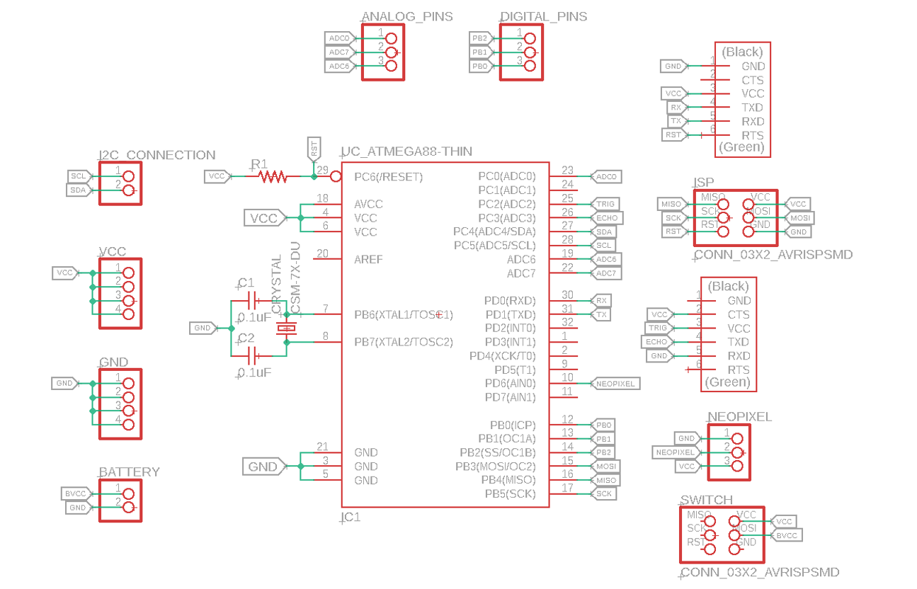
The following image shows the schematics.
Calculating Current Limiting Resistance
As shown in the schematic design. I added a limiting current ressistor for each LED to avoid burning the LEDs. The resistance of limiting current resistor is calculated as follows:
Ohms Law:
Voltage (V) = Current (I) x Resistance (R)
V = I x R >> R = V/I
Supply Voltage (Vs) = 5V (in my PCB)
SMD Yellow LED Forward Voltage (VF) = 2.5 V
Forward Current (IF) = 20 mA = 0.02 A
Therefore, the limiting current resistance equals to:
R(LED) = (Vs - VF) / IF
R(LED) = (5 - 2.6) / 0.02
R(LED) = 120 Ohm
I can use a resistor of 120 ohm or greater as a current limiting resistor, and since the smallest value we have in the lab is 499 ohm I used it.
I used the Bivar Surface Mount 0805 package LED datasheet to find the forward voltage and forward current.
After I finished the schematics, I clicked on the icon Generate/Switch to Board to fix the places of the components and to connet them.
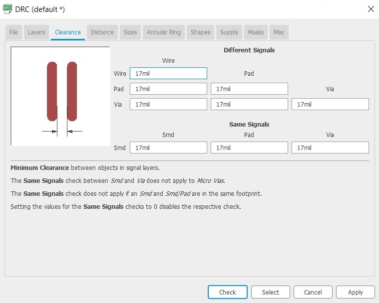
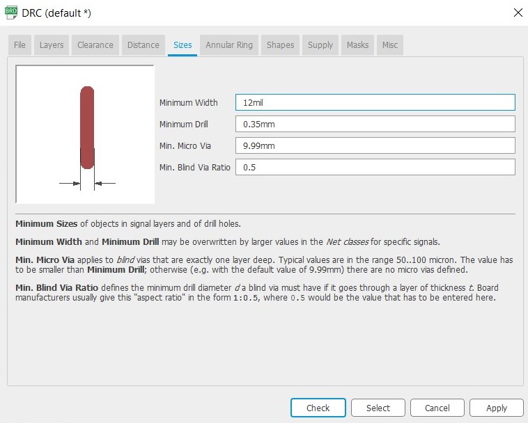
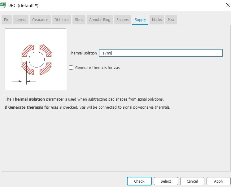
Before connecting I went to DRC to fix design rules.
I put the clearance to 17 mil, the size to 12 mil and the supply to 17 mil.
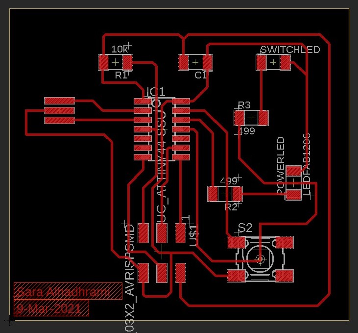
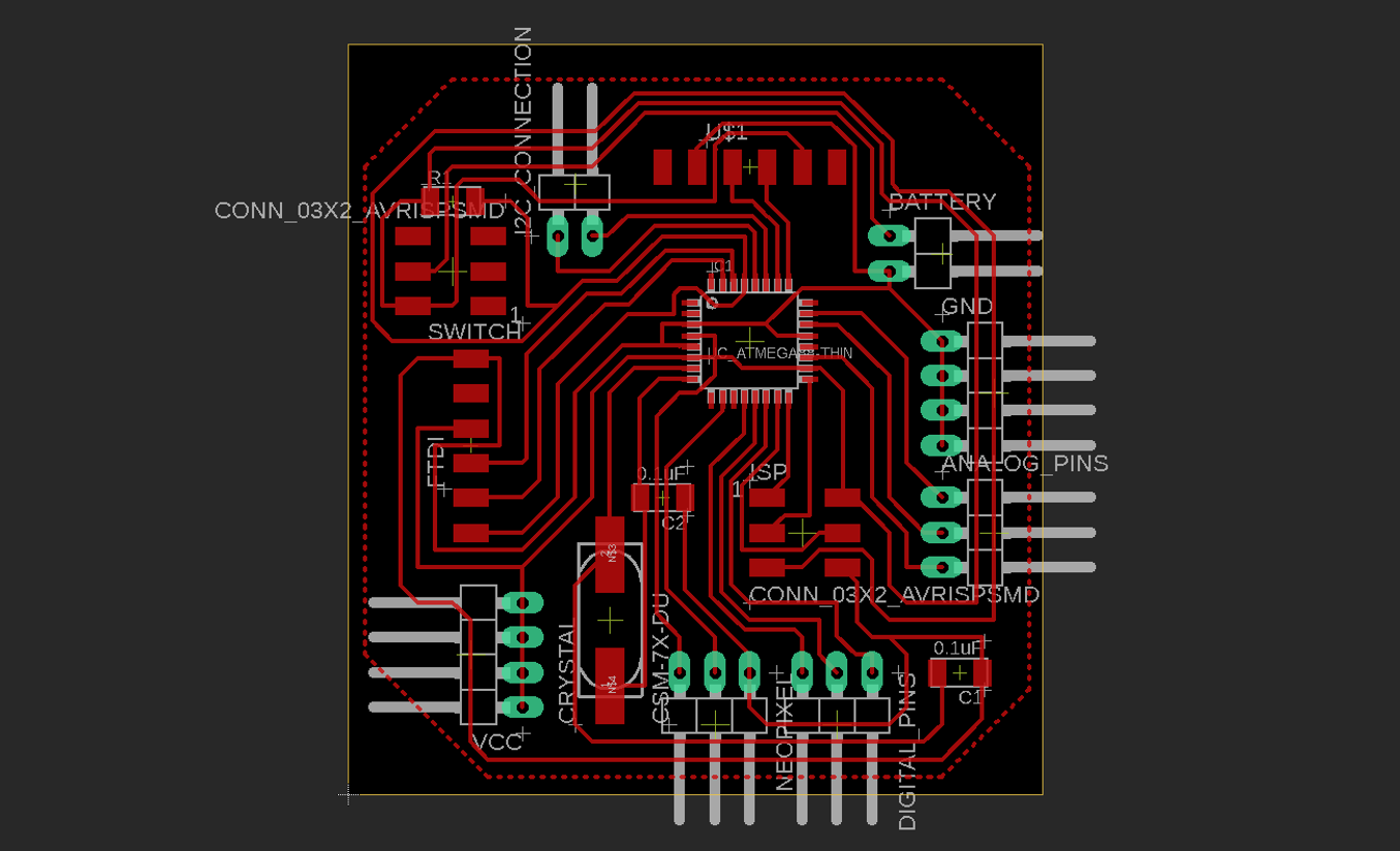
The image below shows the board after connecting all the components.
To put the board design in the milling machine, I should save it as a PNG image.
The stepts of saving PCB design as PNG image: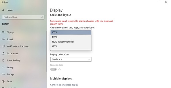
This is layer settings icon 


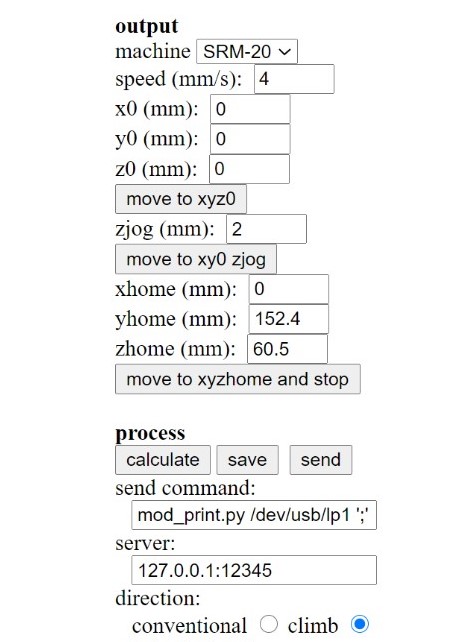
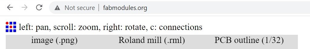
Then I opened the images in Fab modules to convert them to rml file which is the file formula that Milling machines understands
Traces
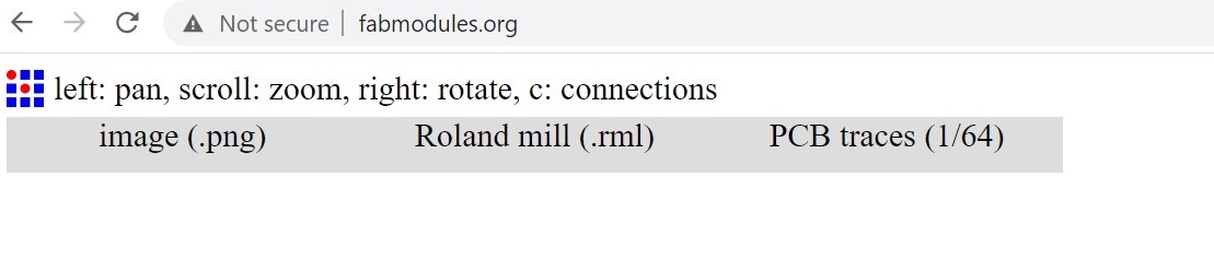
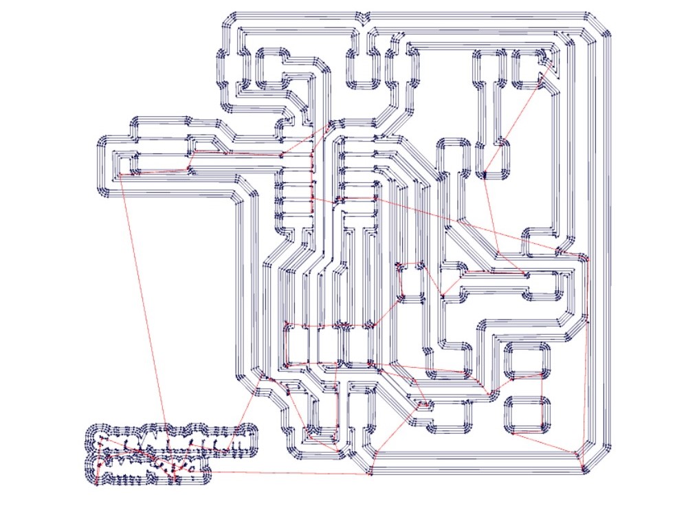
Outline

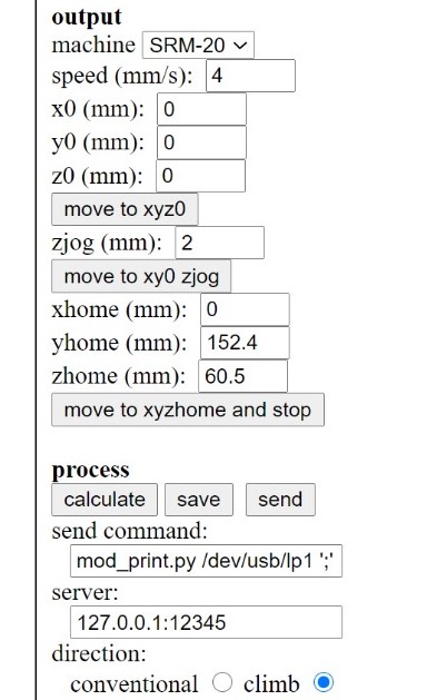
I took the rml files to the milling machine
And here is my board after milling and soldering.
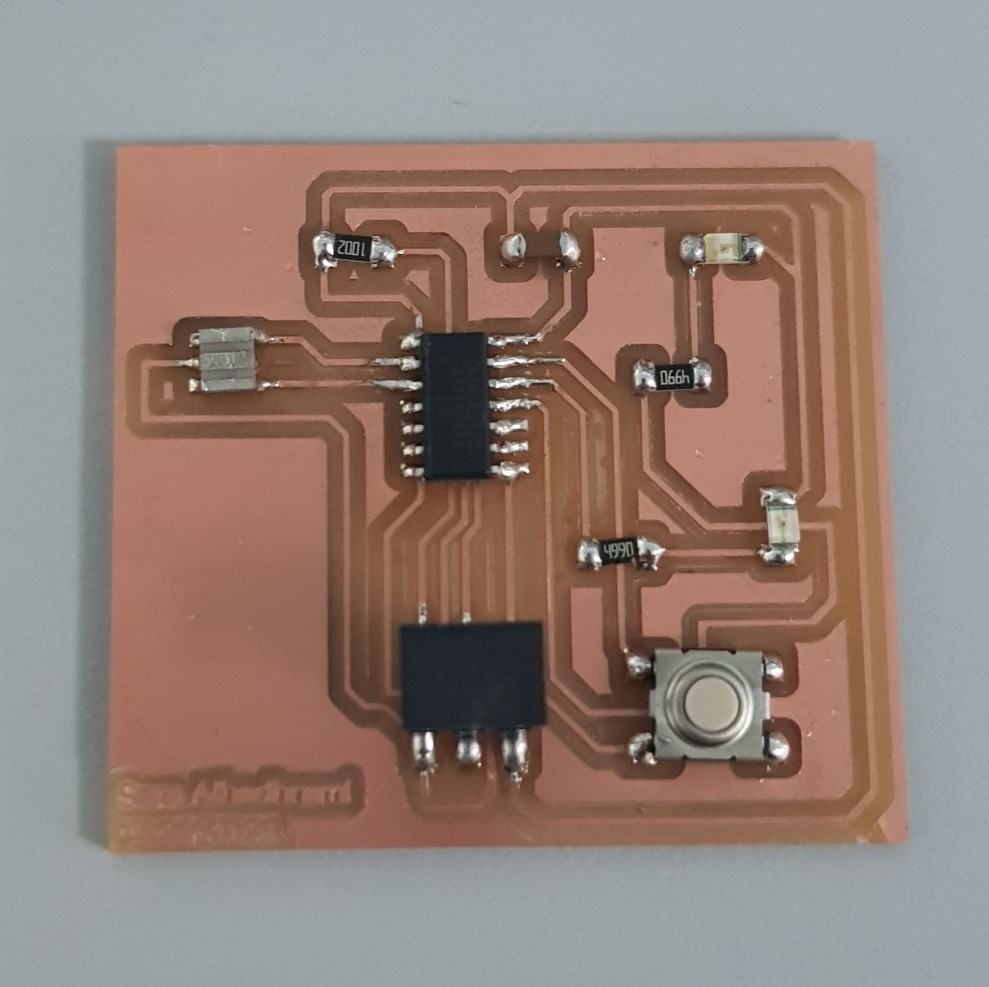
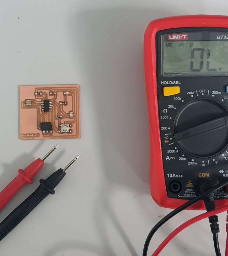
At the end, I used the multimeter to check that all the components are connected properly.
In Embedded Programming week, I uploaded a program to the board to test if my board works
I had no problems, I did each step once without any mistake or problem.
ATmega328P
I used Autodesk Eagle to design a PCB for my final project.
The design consists of: - ATmega328P microcontroller
- Ultrasonic sensor
- Slide Switch
- Headers
- 10K resistor
- 2X 1uF capacitors
- 2500mAh Lithium Ion (LiPo) Battery
- 5V Boost for Lithium Battery JX-887YDC Boost Converter
- Neopixle LEDs strip
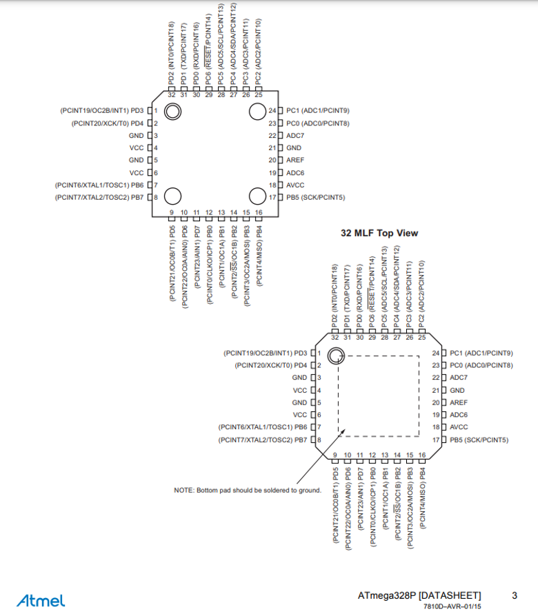
I used Atmega328P Datasheet to find the pinouts of the microcontroller. From the datasheet I knew the digital pins, analog pins, VCC and Ground pins.
I used FlatCAM software to save the pcb. (steps of using FlatCAM are listed in Input Devices week)
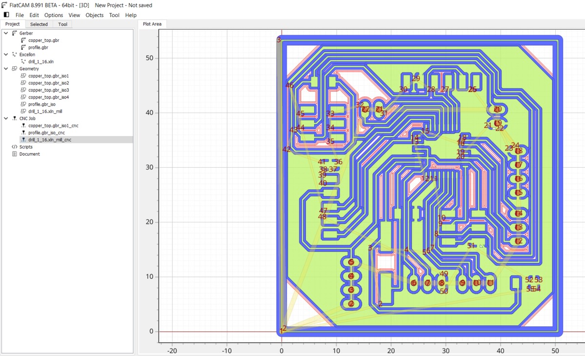
Then I took cnc files to Roland CNC Milling machine to mill the board then I soldered the components
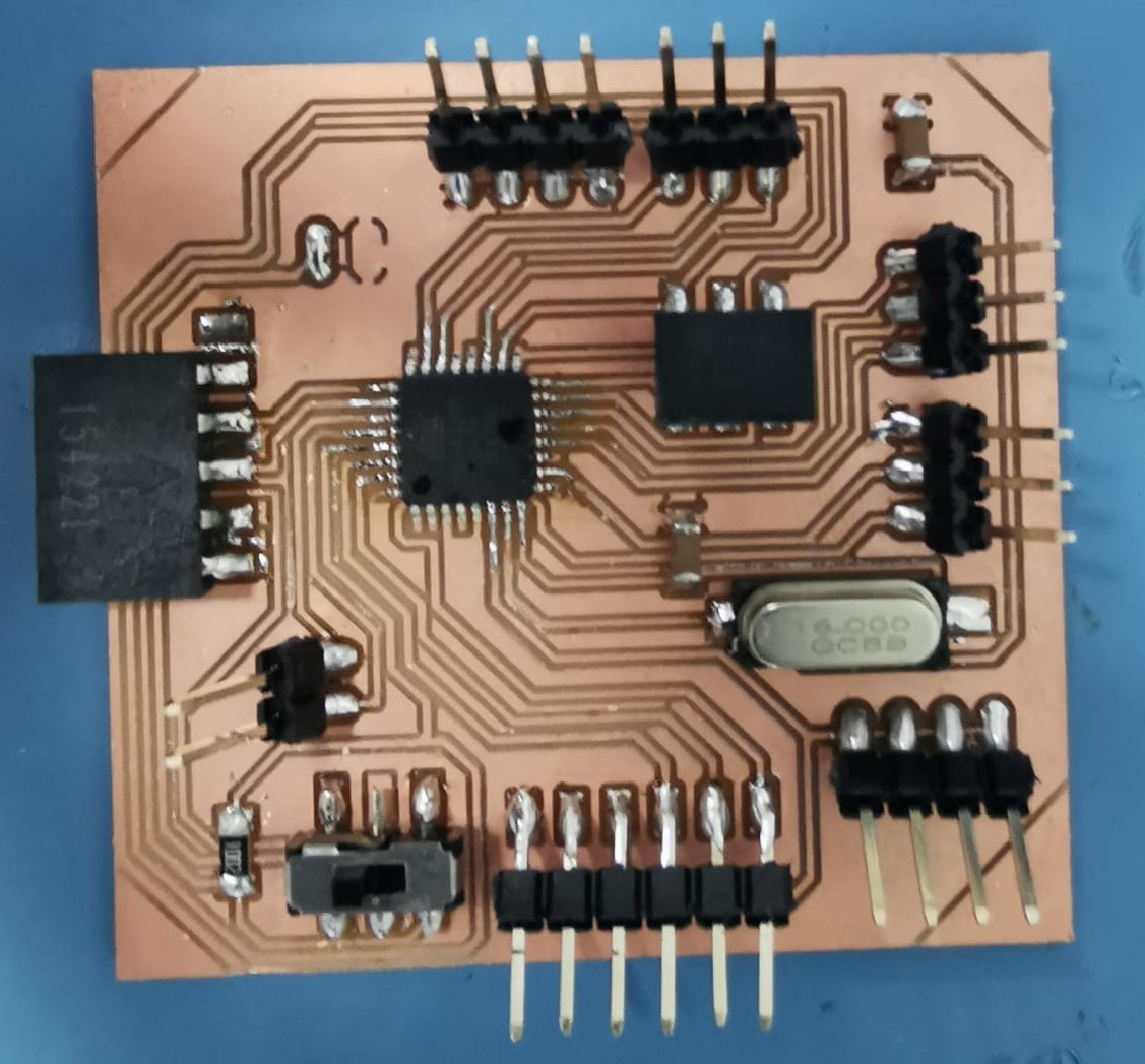
I programmed the PCB by using Arduino IDE
Group assignment:
Group Page LinkFor the group assignment, first I checked the continuety between components by using the Digital Multimeter. The beep sound means pins are connected and when there is no sound means the two pins are not connected.
Then I measured the supllied voltage by connecting my board with the laptop. I used the Digital Mutlimeter and I touched the VCC pin with the positive probe and the negative probe on the GND.
I also used the digital probe to check the pins that are connected to VCC and pins connected to GND. If the Level LED lights up means this pin is connected to VCC and vice versa if connected to GND. First two pins in the video connected to GND and last pin connnected to VCC.
Files list:
| Schematic | Eagle File |
| Board | Eagle File |
| Traces | png File |
| Outline | png File |
Close Project