
Networking and Communications
Group assignment:
Send a message between two projects
Individual assignment:
- Design, build, and connect wired or wireless node(s) with network or bus addressess
Individual assignment:
By reffering to Ana Filipa Silva website, I did I2C Wired Communication between two ATtiny44 boards. This is the only page that I find that shows how to do I2C communication between two ATtiny44 boards.
First, to establish I2C communication, I need to connect SDA and SCL pins in the boards to allow one board to send (Master) and the other board to receive (Slave) as shown in the following image.

This type of comunication could be done easily between boards that built with Atmega microcontrollers. But with ATtiny44 microcontroller is a bit different. From the ATtiny44 microcontroller pinout image, I found that pin A6 is the SDA pin and MOSI pin. And pin A4 is the SCL pin and SCK pin.
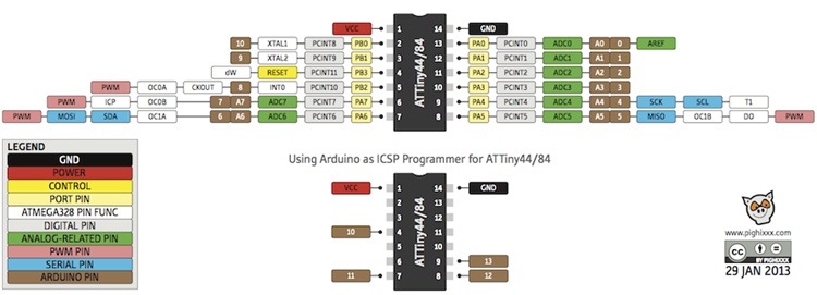
Therefore, to establish I2C communication between two ATtiny44 boards, I need to connect SCK with SCK, MOSI with MOSI and VCC with VCC. Plus two 10K resistors, one between VCC & MOSI and one between VCC & SCK.
I used two ATtiny44 boards that I designed before in Electronics design week and Input Devices week. I also designed and fabricate a small additional board that includes two 10K ohm resistors and headers to connect the PCBs together.

This is the additional board


I connected them in this way

Programming:
I adedd two libraries to Arduino IDE software. The TinyWireS library, and it works with ATtiny44 and its used for Slave board only.
And I used the USIWire library for the Master since TinyWireS couldn't be used for Master board.
The folowing images show the codes that Ana wrote.
Master Code (Source)
Slave Code (Source)

The source codes should work as follows:
The LED in the Master board should blink continuesly to show that the board is working. And one LED in Slave should blink to show its working as well. Then if Slave recieved bytes from Master, another LED in the Slave should light up.
I did some modifications to the codes because I want it to work in a different way.
Modified codes should work as follows:
The master code should send one byte to the slave, then after 500ms transmission will end. This will be repeated continuesly since its written in a loop.
And for the slave, if bytes are being received from the master, the LED in slave board should keep blinking. And if the button in slave is pressed, the LED should stop blinking even if bytes are being recieved.

Slave Code (Modified)

Codes should be uploaded through TinyISP to each board seperately. Then I connected the boards together through jumper wires. The PCB I designed in Electronics design week I used it as Slave and I used the PCB I designed in Input Devices week as Master.
Then I connected the FTDI cable with the Master board.
Codes worked successfuly.
The red LED (the LED located near to the button) in slave board is blinking, which means there is a connection and it recieves bytes from master board. And LED stops blinking when I press the button.
Group assignment:
Group Page LinkFor the group assignment I did I2C communication with my colleague Mohammad by using Atmega and ATtin44 boards.
Files List:
| Master Source Code | Arduino IDE File |
| Slave Source Code | Arduino IDE File |
| Slave Code (After changes) | Arduino IDE File |
| Master Code (After changes) | Arduino IDE File |
| Additional pcb (board) | Eagle File |
| Additional pcb (schematics) | Eagle File |
| Additional pcb (traces) | png File |
| Additional pcb (outline) | png File |
Close Project