9 - OUTPUT DEVICES
Individual assignment:Add an output device to a microcontroller board you've designed, and program it to do something Group assignment:Masure the power consumption of an output device/li>
Group assignment
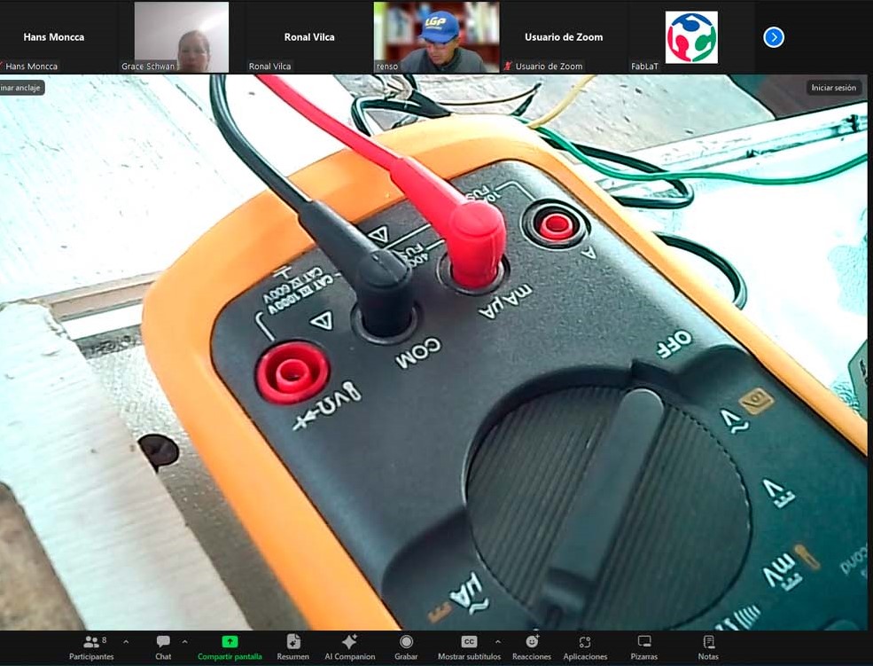
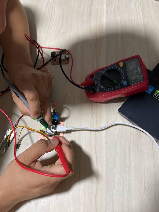
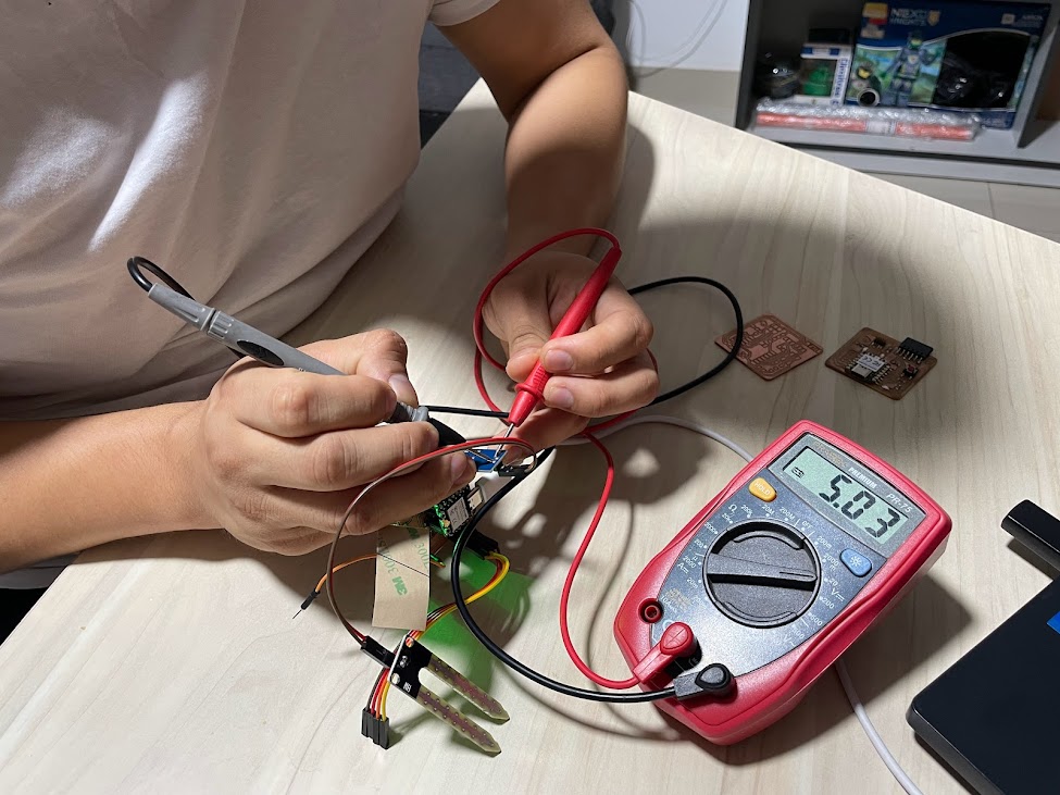
we had a great group meeting where Ronald showed us how to use the multimeter to measure voltage and amperage on our boards. It was very helpful because it gave us a clear idea of how to get accurate readings and understand what is really going on in our setups. We learned a lot about how to connect the multimeter correctly and what settings to use to measure different things.
TESTING
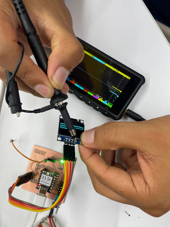
When we look at the oscilloscope image, we notice that we are receiving the signal from the program we have placed on our Quentorres board. And the best thing is that everything seems to be in order according to what the oscilloscope shows! This is really encouraging and tells us that our design is working as we expected. However, even though everything seems to be fine so far, it is important to continue to perform additional tests to ensure the consistency and reliability of our system. In addition, we must carefully document our results and conduct further tests to confirm that our board is performing stably under various conditions
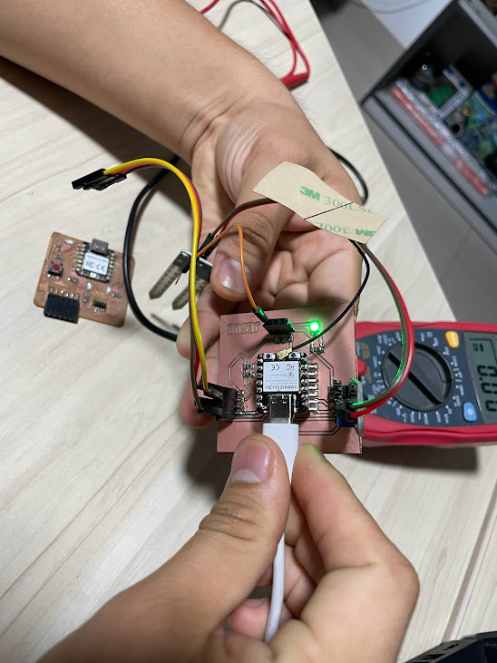
In the picture, we can see the various plates belonging to my friends and me. We were running tests to make sure everything was working properly. It's great to see how each of us is progressing on our projects and how we are working together to make sure everything is in order. We are committed to the success of each of our designs and are willing to work together to make it happen. I'm excited to see how each board develops and hope we all reach our goals successfully.
-
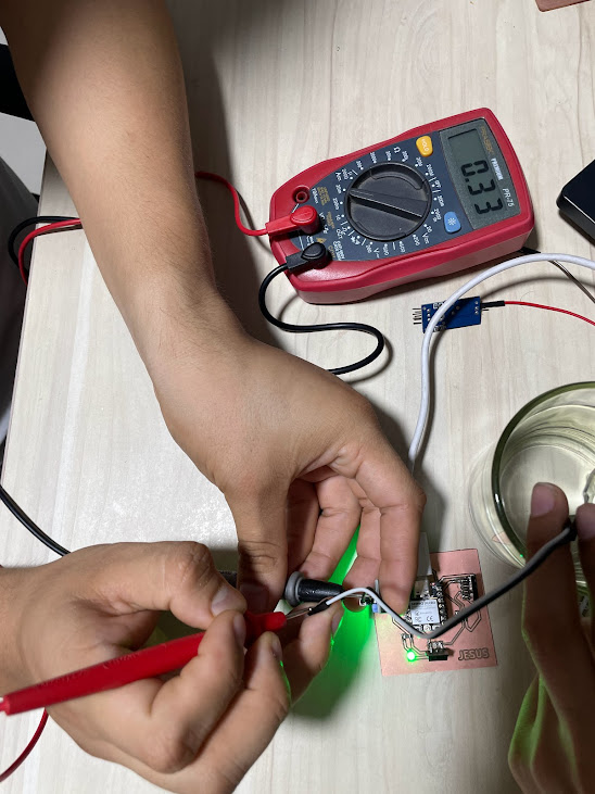
With the multimeter, I can measure several important things on our boards. For example, I can measure the voltage at different points in the circuit to make
sure the components are getting adequate power. I can also measure the current to verify that there are no overload problems. In addition, I can measure the
resistance of the components to make sure they are within the expected limits. I can even check the continuity of the electrical connections! is an excellent tool for our practices.
-
The oscilloscope allows us to see how the electrical signal behaves over time.
I can observe the waveform of the signal and measure its amplitude, frequency and period.
This is useful for understanding how our circuits are performing and for detecting problems such as ripple in the power supply. I can also measure the pulse width of digital signals, which is useful for verifying the accuracy of the pulses in our control circuits.
Conclusions
Individual assignment
To import a footprint library into KiCad:
- Download the Library: First, ensure that you have downloaded the footprint library (usually in a .pretty format) that you want to import into KiCad.
- Launch KiCad: Open the KiCad software on your computer.
- Footprint Editor: In KiCad, navigate to the Footprint Editor. You can find this under the "Tools" menu in KiCad8, "Edit" menu.
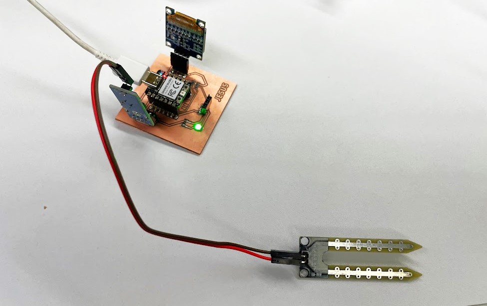
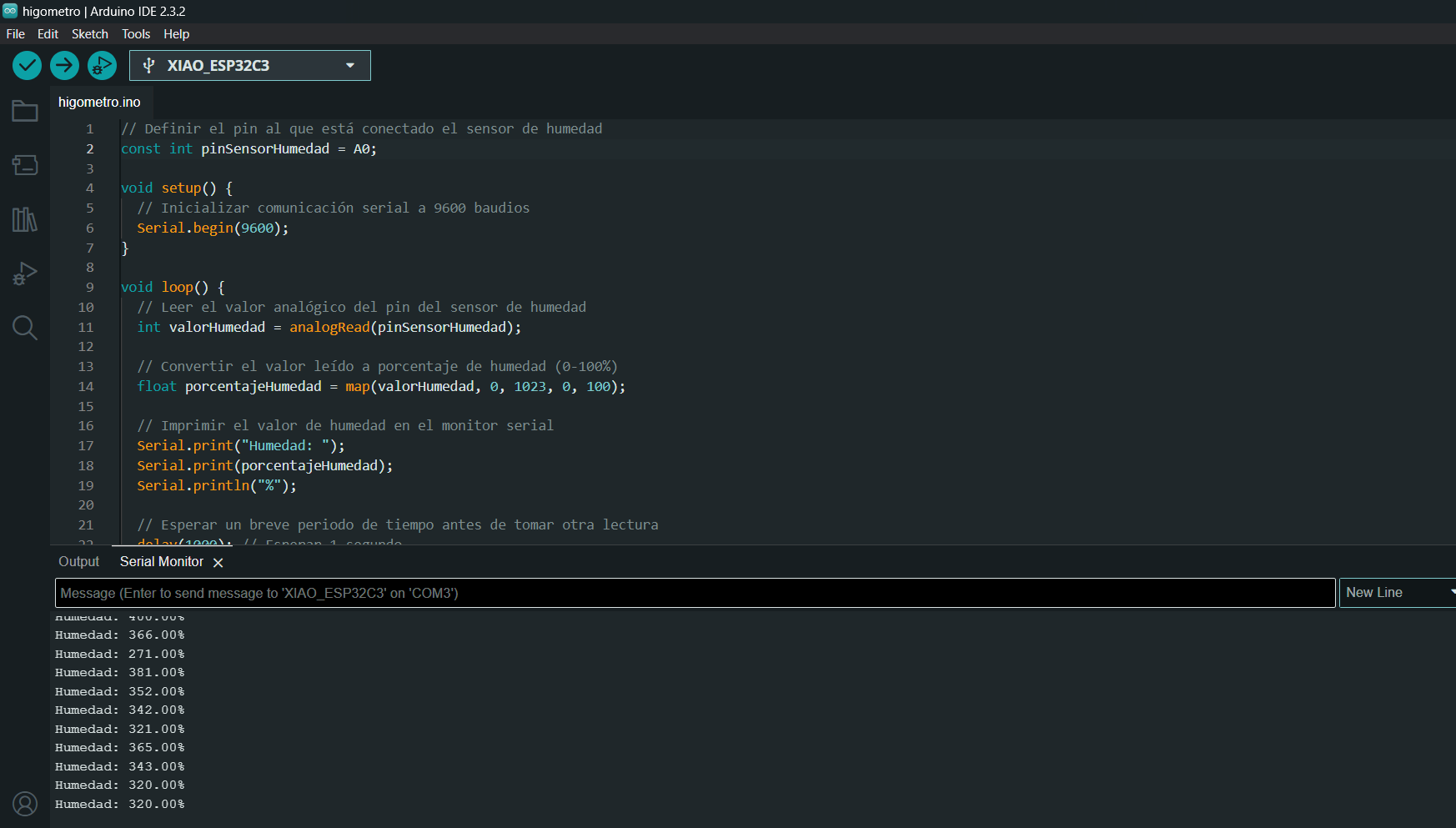
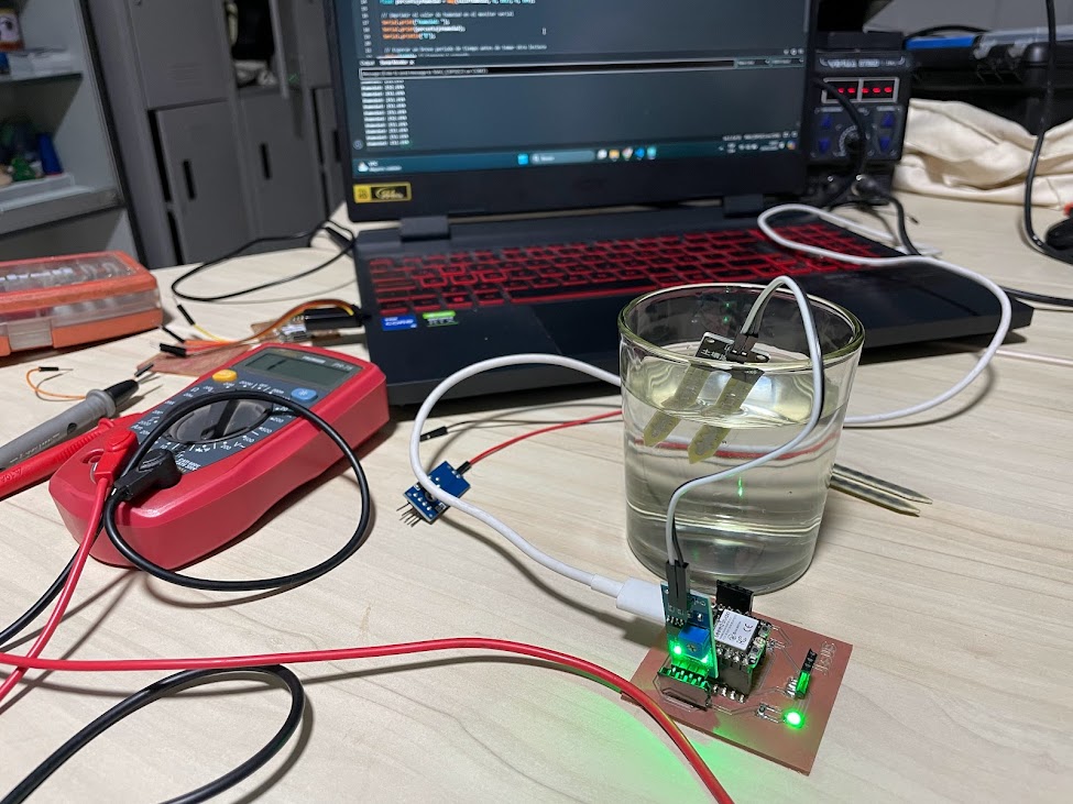
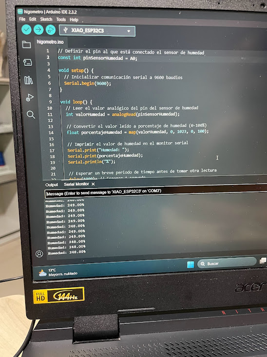
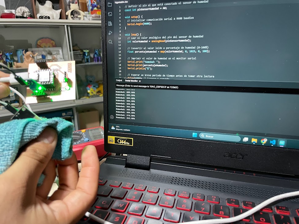
Hygrometer session
Download it in ZIP format to obtain the liberia files as shown in the photo.
It seems like you're providing a step-by-step guide for importing symbol libraries specifically in KiCad. Here's a refined version of your instructions:
- Open KiCad and navigate to the "Preferences" tab.
- Choose "Manage Symbol Libraries" from the options.
- lick on the folder icon to browse for the file
- Once you've located the file, click "Open".
- You'll notice that it has been added to the list of libraries.
- Finally, click "OK" to confirm and save the changes.
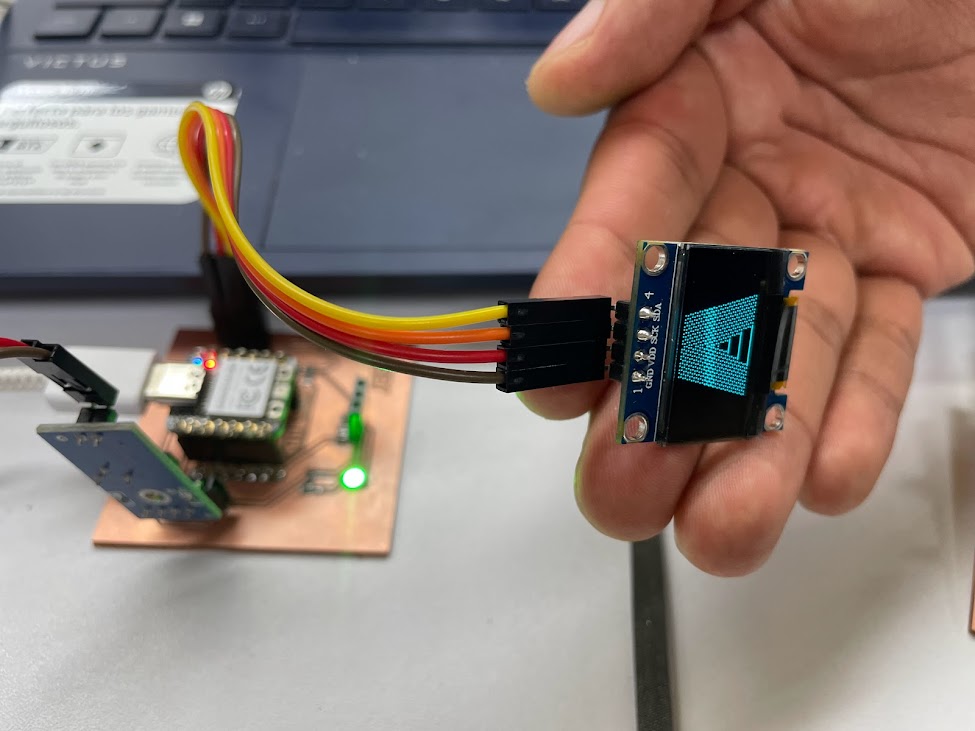
OLED DISPLAY 0.96"
SPECIFICATIONS AND FEATURES
- Operating Voltage: 3V - 5.5V DC
- Driver: SSD1306
- Interface: SPI
- Humidity measurement resolution: 1% RH
- Resolution: 128*64 pixels.
- Monochrome: white pixels (black background)
- Visible area (display): 23*11.5 mm
- Working temperature: -30ºC ~ 70ºC
- Dimensions: 27*27*4.1mm