Grace Schwan Silva
  • Home (current)
  • Student Agreement
  • About me
  • Final Project
  • Assignments
    Week1:Principles and Practices, Project Management Week2:Computer Aided Design Week3:Computer Controlled cutting Week4:Electronics Production Week5:3D Scanning and Printing Week6:Embedded Programming Week7:Computer Controlled Machining Week8:Electronics Design Week9:Output Devices Week10:Mechanical Design, Machine Design Week11:Input Devices Week12:Molding and Casting Week13:Networking and Communications Week14:Interfaces and Applications Programming Week15:Wildcard Week Week16:Applications and Implications Week17:Invention, Intellectual property, and Income Week18:Project Development Final Project

WEEK 3

COMPUTER CONTROLLED CUTTING

Assignment :

Group assignment:

* characterize your lasercutter’s focus, power, speed, rate, kerf, joint clearance and types

Individual assignment:

* Cut something on the vinylcutter

* Design, lasercut, and document a parametric construction kit, accounting for the lasercutter kerf, which can be assembled in multiple ways, and for extra credit include elements that aren’t flat

This week we have two tasks; one individual and one group. I start the group task:

GROUP ASSIGNMENT

For this group assignment we use the laser RAYJETr500 CO2 pantograph for simple laser cutting and engraving.

WORK SURFACE MACHINE SIZE LASER POWER LASER TYPE
up to 1300 x 900mm an 1550 x al 1080 x prf 1080 mm 60 a 100 W Láser de CO2
- an 1870 x al 1700 x prf 1110 mm 60 a 120 W Láser de CO2

PROCESSABLE MATERIALS CUT ENGRAVE
Advertising articles X X
Leather cut X X
Dřevo X X
Metals X X
Paper X X
Plastics X X
Pohárů X X
Seals X X
Signaling X X
Textile X X
Glass X X

Technical Data:

  • Laser Power of 60 to 120 watts.
  • Type CO2 laser.
  • Cutting and engraving of acrylics up to 1.5 cm.
  • Wood up to 1.5 cm textiles
  • Paper and much more
  • We used the Focus Tool and set the value to 2 as recommended by the Trotec expert.

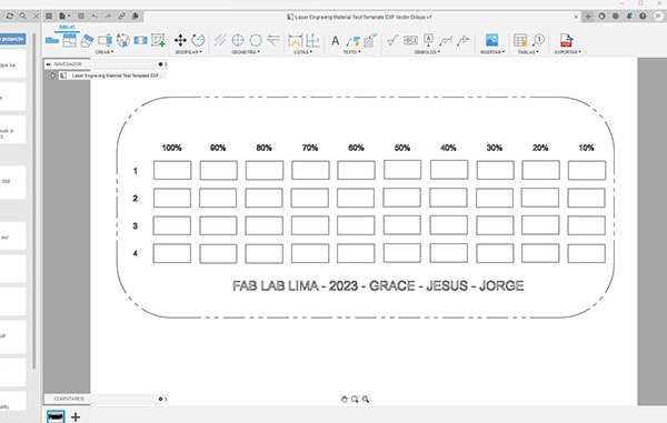
    In Autodesk Fusion 360 we create a test layout that features squares with different power and speed values. Since the native Rayjet program does not accept dxf files, we exported the file to Inkscape to assign the colors to each square.

    For the first etch test, the speed and PPI settings remain the same, while the power decreased by 10% for each square, which is from 100% to 10% power. From 100% to 50% power the engraving works fine, the main difference is in the depth of the engraving, from 70% and less it is difficult to see on cardboard. 40% produces an almost silky-white print that looks great. 30% and less did not produce any prints.

    To export to Rayjet Manager, we send the file to the printer named Rayjet Manager.

    There was a problem with the machine recognizing the yellow layer (corresponding to 80% power) and this engraving setting did not plot, so I assigned another color to this setting.

    We then corrected the RVB values and blended the colors so they could all be recorded.

    The inkscape file can be found here.

    In order to test the focus, power, speed, rate, cut, download the following test from the page this link

    then download the SVG file and send it to INKSCAPE so I can verify and place my name.

    Then I download it as a DXF file to be able to take it to the RDWORK program to be cut in the laser.

    Kerf Check Parts

    I found a very interesting fab Academy page to be able to generate my cutting clearances and joints test on the page of Atsufumi Suzuki, Fablab kamakura graduate in 2022. Kerf Check Parts Generator

    Here is the hero photo of the board rule.

    You'll find the board rule file here

    Individual assignments

    In this week we have as exploration mission about computer aided manufacturing using laser cutting machine and vinyl cutter. This week I made a parametric snap-fit kit, I cut it on the laser and made some beautiful stickers that turned out great hehehe.

    How I did them, then I'll tell you, let's go there!

    We had to make a route for the beautiful vinyl cutter so that we could fulfill our assignment and it was courtesy of our dear uncle Geny (the uncle of all the children in the world...google him and you will find him .) member of my FABmilia in Peru. It's already here at home :

    But before explaining how I did it, we will know a little:

    1.-VINYL CUTTER

    What is a vinyl cutter?

    Vinyl cutting is a tool to develop computerized graphics for posters, stickers, signage, exhibitions, etc., it is ideal for its speed, durability and low cost and is computer controlled.

    The computer controls the movement of a sharp blade over the surface of the material. This blade is used to cut shapes and letters from thin self-adhesive plastic sheets called vinyl, but we can also use other materials such as fabric. paper, cardboard, etc.

    It is necessary to know the materials in advance for a correct operation for better results. We need a computer and the program with which the design is developed.

  • PLOTTER:
  • Similar to a large printer, instead of inserting common paper and printing with ink, it works with the vinyl and cuts it, it consists of a head that moves from side to side of the machine in a transverse direction, in this head it has a small blade ; and then there are the rollers that are responsible for making the vinyl run backwards or forwards, there are plotters of a variety of sizes ranging from 15 inches, 24, 36, to 48 inches.

  • CUTTING PROGRAM:
  • It is a software that allows us to link with the plotter, it allows us to send the drawing or the design to cut and it is vector graphics design programs such as: Corel, Illustrator, Inkscape, etc.

    Now that I have an idea of what it consists of, I begin the exploration:

    The machine we are using for the vinyl cutter is ScanNCut 2 CM650W , it is a domestic cutting machine with a built-in scanner. It has an LCD touch screen, a 30 x 60 cm scanning area, WiFi wireless connection, it cuts paper, vinyl, acetate, foam, balsa wood, magnet, fabric and silicone (up to 2.3mm thick depending on the material) and with the free Brother Canvas software that allows you to download, edit and create drawing or cutting pattern data. It has default designs and letter molds that make your life easier.

    main features:

  • Large scanning area: RGB color recognition.
  • 300 DPI scanner: Create your own cut files.
  • Standalone: 1,102 layouts and 15 built-in fonts.
  • Precision cut: German steel blade, Japanese design quality.
  • SVG Data Readability: Use your existing art files, no need to buy more.
  • ScanNcut Canvas: Edit and design your creations from the free web app. Visit(ScanNcutcanvas.brother.com).
  • Readability of PES and APS data: Full Compatibility with design files for embroidery machines.
  • Work space:

  • Blade holder adjustment levels 12.
  • Cutting speed adjustment levels 5.
  • Optional 12" x 24" (30.5 x 61 cm) work area with additional mat.
  • Work area 30.5 x 30.5 cm (12" x 12").
  • Process:

    FABACADEMY sticker design, FABLAB PERU and my name:

  • I explore the INKSCAPE program, a 2D design program that allows me to vectorize the images of the logos that I made.
  • I import the images to use, and then I used an option called “vectorize bitmap”, but it came out very thick and with some missing parts, I thought it would be easier ;(
  • I went to my second option with the “Bézier” tool drawing the outline of the letters and figures. i made it!!
  • I save the images in SVG format.
  • I opened the Canvas Brother page, downloaded the software, logged in and the magic began.
  • I import the image that I vectorized, I have to say that in this part it takes me a little time because when importing I forgot several details such as grouping or separating the areas that would be of different colors, because later with the file in the cutter you can't make changes.
  • The good thing about the software is that it allows you to simulate the position of your figures or letters, arrange and edit them.
  • Once I was sure it was the correct distribution, I save it to a USB. (Remember that it also has wifi, I didn't do it via wifi because my signal is terrible lol)
  • Very well! now to cut!

    Cutting process:

  • The first thing I did was place the machine in a large area so that the cutting mat would have freedom of movement when cutting and scanning.
  • I then turned it on by pressing the power button on the top left of the touch screen.
  • I opened the door that protects the part of the rollers where the cutting mat and the blade go.
  • I put the blade in its respective place. It is very important to see its calibration, in my case the perfect calibration is number 4.
  • IMPORTANT! Before placing the cutting mat in the machine, place the adhesive vinyl, with the help of the spatula adhere your material. I put several colors to save time.
  • I press the button that secures the mat and plug in the USB.
  • With the help of the touch screen pen I select the “Pattern” tab.
  • I went into the shared data tab, selected the file I created, and selected the drawing I would cut.
  • Then I do a mat scan because I want to know if my drawing and the size of the material I placed match.
  • Once I have configured those details, I start to cut wiiiiiiiiiii!
  • They came out great!

  • Once I remove the cutting mat with the material, I turn off the machine and close the protective cover.
  • I remove the cut material, amazing to see that those messy pieces would create these beauties lol..love it!
  • With the help of pliers and a needle I remove the pieces and glue them together, putting them together like a puzzle.
  • Total success, I feel very proud of myself! I'll get better with practice.
  • 2.-LASER CUTTER

    What is a laser cutter?

    It is a machine that allows cutting or engraving with the help of a control command from a 2D program. A laser launched at high power is concentrated on a fragile surface and thus manages to cut or engrave.

    The laser can be source or pulsed. The CO2 source laser is the most commonly used. It allows cutting many more materials and at a higher speed than the pulsed laser. It is considered more reliable, efficient, robust and easier to operate than all other lasers.

    What is laser cutting technology?

    I learned that laser cutting is a method of transforming a 2D file into a physical object. This technology can be done on different materials such as plastic, glass, metal, wood and cardboard. Laser cutting is possible by creating a 2D vector file.

    This file provides information to the laser cutter that will cut the chosen material. It is not necessary to have strong design skills to use laser cutting, but it is preferable to learn the basics of designing and using the machine.

    Laser cutting allows:

  • High level of precision and positional accuracy.
  • Material savings.
  • High production speed.
  • Sharp and clean edges.
  • Minimum deformation of the material.
  • Secure processes.
  • The machine we are using is:

  • Place the material on the laser bed, possibly supporting it with weights.
  • Align the z axis of the laser head (if it is new material) with the acrylic aligner.
  • Open the design in RDworks on the connected PC.
  • Configure the lines with the speed and power settings that you think are necessary.
  • Turn on the laser with the leftmost switch on the machine above the controller Start the air ventilation machine.
  • Start the air ventilation machine.
  • Pulse Start. It is important that you stay with the machine until it finishes cutting!
  • Once this is done, turn off the laser (with that same switch to turn it on) Wait a bit for the air vent to do its job. Turn off the air vent open the lid.
  • EXPLORING CLUTTER

    SLICER - FUSION 360

    I use this software, the first thing I do is download it, to make the fittings of my hand pieces that I downloaded from a page that I leave here. The software was very easy to use.

    The first thing I did was look for a page where I could download a hand and then make it into sheets. Here.

    Once I have downloaded the 3D hand, I choose the types of laminate that the program has in the menu on the left.

    Shorten!

    The first thing I do is clean and arrange the design in Corel Draw, and then save it in DXF.

    I download it to my USB and then I take it to the machine that has the program that handles the laser cutter.

    The software that the laser uses is RDWORK and something that I had not seen in Corel is to remove the duplicate lines, YOU MUST CLEAN THE IMAGE WELL BEFORE SENDING TO CUT SO THAT THE LASER DOES NOT WORK MUCH! I can happily remove those lines in the laser cutter program.

    These are the parameters used by the laser cutter.

    I want to thank teacher Gustavo Atencia, a crack! for opening the doors of the Fab Lab for me, he is in charge of the Fab Lab that is in the emblematic Meliton Carbajal school in Lima next to the Fab Lab IFurniture, thank you very much. Thanks to my super instructor Vanessa Caycho it was possible to do the coordination, I love you!!

    Arming my hand!

    The files I used are located here. HAND PART 1 SDR

    The files I used are located here.HAND PART 1 DXF

    The files I used are located here.HAND PART 2 DXF

    The files I used are located here. HAND PART 2 CDR

    The files I used are located here. HAND PART 3 DXF

    The files I used are located here. HAND PART 3 CDR

    The files I used are located here. HAND PART 4 DXF

    The files I used are located here. HAND PART 4

    The files I used are located here. CALIBRADOR DXF

    The files I used are located here. CALIBRADOR CDR

    The files I used are located here. CALIBRADOR RLD

    FUSION 360

    To create my parametric construction kit the first thing I did was:

    I start by opening the fusion 360 software. I click on the option to create a new file. I display the interface and choose the option create sketch that There is the toolbar at the top.

    I choose the work plane, use the create a sketch tool and choose rectangle.

    I place the measurements (60 mm long x 60 mm wide) and add dimension to the sketch with the measurements.

    Inside the main figure I center a rectangle 12mm high x 3.1mm wide on the upper face.

    I use the cut tool to remove the excess and repeat the same process on the missing parts.

    I finish by exporting the file in DXF format.

    I followed the same steps to create the octagons and then multiplied them together with the squares to make the kit.

    Then I pass the DXF file to the RDWORK laser cutter program.

    And I started cutting the pieces for my construction kit.

    I used the following parameters: Speed ​​20 - Power 55

    Here is the hero photo of my construction kit.

    Creative Commons License
    This work is licensed under a Creative Commons Attribution-NonCommercial-ShareAlike 4.0 International License

    FOLLOW
    • © Untitled. All rights reserved