
Output Devices
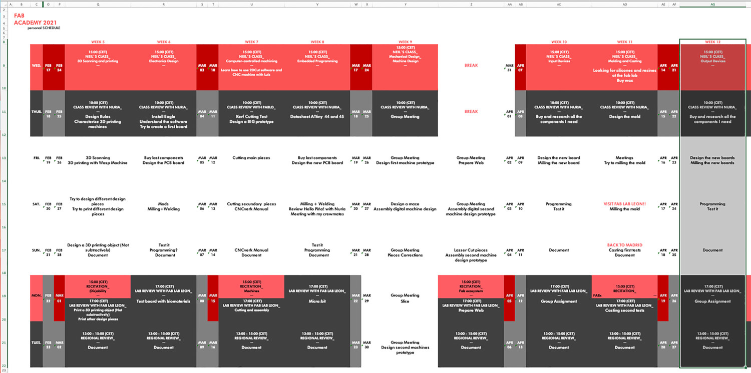
WEEK 12
(21/04/2021 18:06 p.m.) Wednesday afternoon. What nerves and tension I had! For second time, I have volunteered to expose my Molding and Casting work to Neil!😱😱 During this last week I have had a great time experimenting and cooking new materials for the molds I made in León last weekend 💚💚💚.
Adrián and my crewmates from Fab Lab León 💚 encouraged me again to show Neil all the work I was doing during the week. And it seems that he and my classmates liked it a lot! 😍😍
I hadn't cooked biomaterials in a long time and I missed them very much 😢. Thanks to Nuria I could relive the experience 💜, and in the next few weeks I have had a couple of workshops on biomaterials and digital fabrication that I am looking forward to doing. 😍😍
This week we return with Electronics ... this time with Outputs.
Chan, chan, chan (dramatic sound).
Is drama coming? 🤔😱
(23/04/2021 11:05 p.m.) So far, we have started the week well and step by step, thanks to the help of my crewmates and Adrián who helps us in everything he can with Electronics💚💚💚. (23/04/2021 21:55 p.m.) This weekend, Nuria has come to Madrid! And she has brought electronic presents for me and Mauro along the way. It was nice to see you again and give you a hug 😍.
We have to start putting fifth gear 🏎. The final countdown has starting! and we have to focus on our final projects and finish the assignments that we have unfinished.
(24/04/2021 09:12 a.m.) This Saturday, I go back to old ways with my crewmate, Alberto at the fab lab UE Madrid, to mill and program our boards! Hopefully, everything goes well. Wish us luck!! 🙏
To start this intense week with energy, we are going to begin with a more alternative song. So, the week song´s My Songs Know What You Did in the Dark (Light Em Up) by Fall Out Boy . 🔥
My songs know what you did in the dark
So light em up up up, light em up up up
light em up up up, I'm on fire.
Organizing tasks
Like previous week, we have two types of assignments, one's group and other individual. So as usual, I organize my schedule and here the following Evaluation Criteria that we have to approach to complete the Assignment:
- ✓ Measure the power consumption of an output device
- ✓ Document our work
- ✓ Documented how we determined power consumption of an output device with our group
- ✓ Documented what we learned from interfacing output device(s) to microcontroller and controlling the device(s)
- ✓ Add an output device to a microcontroller board we've designed
- ✓ Program the board to do something
- ✓ Described our design and fabrication process
- ✓ Explained the programming process/es we used
- ✓ Explained problems and how you fixed them
- ✓ Included our design files and codes
Extra credit
- ✓ Include a "hero shot" of our board
Group Assignment
- MEASURE THE POWER CONSUMPTION OF AN OUTPUT DEVICE
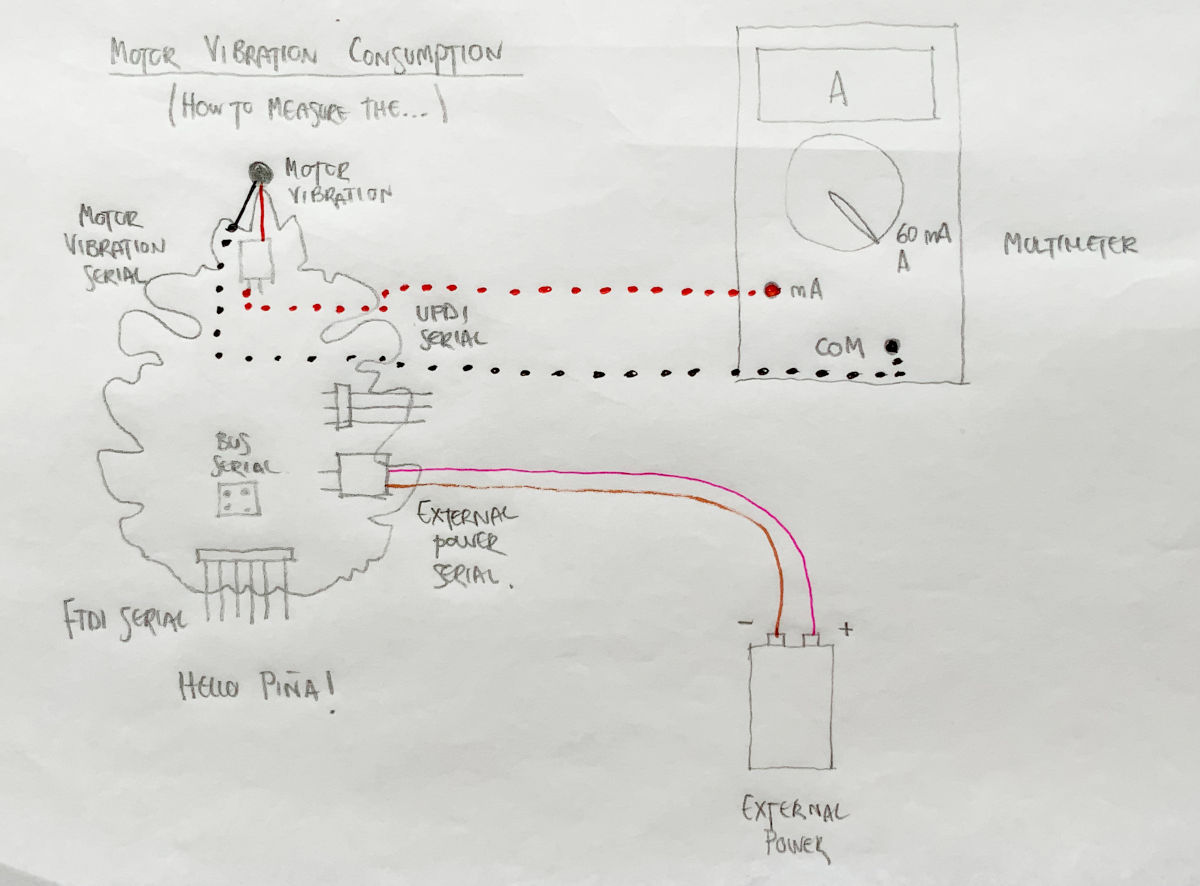
(27/04/2021 12:18 p.m.) Once we have achieved our Hello Piña! 4.0 works!, we are going to measure the energy consumption of the board and the output, which is the vibration motor.Following Adrián´s guidelines that he explains in his group assigment documentation, to measure the electricity consumption of any electronic object, we use the multimeter to measure the amperage.
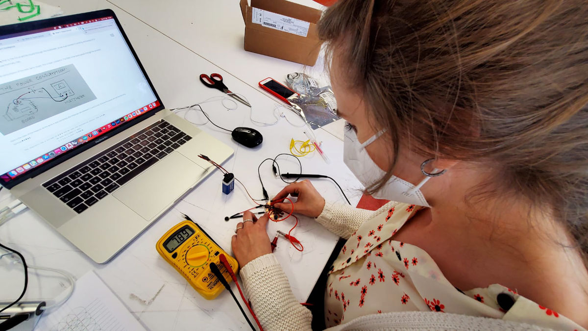
One things Adrián explains us is that to measure consumption, we must close in series the circuit between the multimeter, the battery and our board. And measure the consumption on a small scale (in my case the minimum amperage measurement is 60 mA)
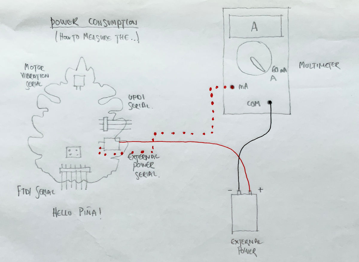
So, following the example of Adrián and my crewmate Sergio, I draw what would be the schematic of my circuit to measure the power consumption of my board.
We have to connect GND of our battery with the Amperometer connector of the multimeter. We close the circuit by connecting VCC with the positive pole of the battery, and finally, with the connector we measure the amperage enters on board.
As you can see in the video, the amperage variation goes between 11 mA - 23.1 mA Having a 4.75 V power regulator and taking the highest consumption value that has been measured, 23.1 mA, we apply the formula, to measure the power P = V x I:
P = 4.75 V x 0.0231 => P = 0.11 W.
Now we are going to measure the consumption of the vibration motor. We have to do is connect the GND of the vibration motor with the multimeter, and insert the VCC pin of the vibration motor on the board. Now with the Amperometer we measure the amperage in GND.
As you can see in the video, the amperage variation goes between 15.9 mA - 15.7 mA Having a 4.75 V power regulator and taking the highest consumption value that has been measured, 15.9 mA, we apply the formula, to measure the power P = V x I:
P = 4.75 V x 0.0159 => P = 0.075 W.
(27/04/2021 12:19 p.m.) In this video, Alberto and me started doing our respective Group Assignments at fab lab UE Madrid, but we made a small mistake. In my case, instead of measuring the amperage, what I was measuring was the voltage in each vibration pulse that I had programmed into the board. Here you can see the variation:
Individual Assignment
HELLO PIÑA! 4.0 (MOTOR VIBRATION)
(22/04/2021 10:57 a.m.) During our local review, In this assignment, Nuria has advised us that we have to try to test some of the outputs we want to integrate in our final project.
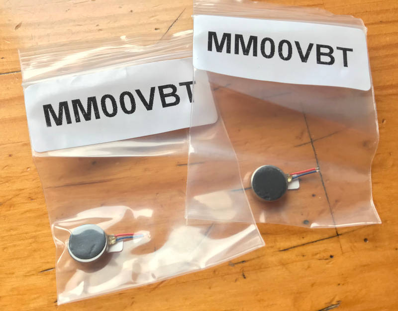
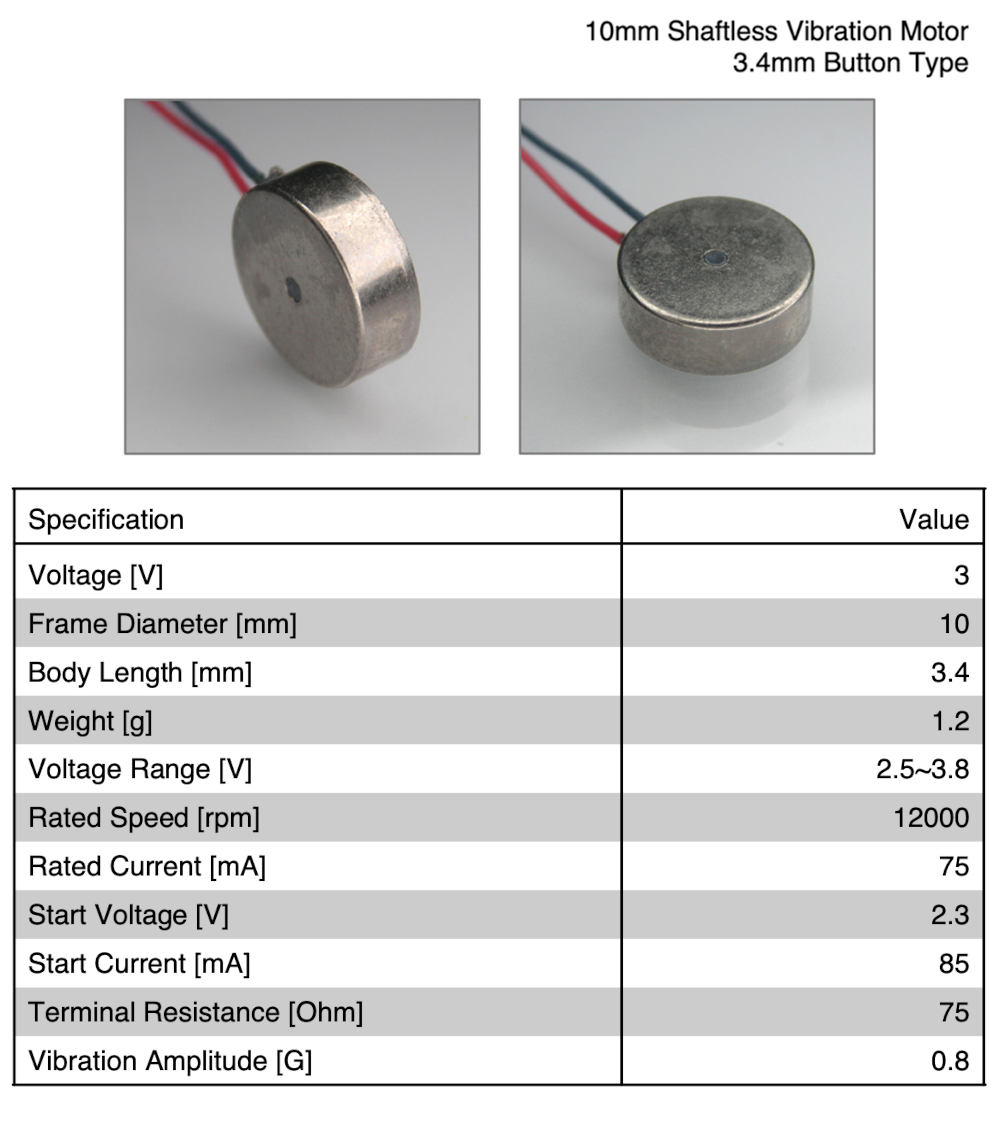
In my case, I have opted to test with vibration motors that I want to incorporate into the wearable. For the project I have opted for a miniature vibration 3V Motor (Datasheet).
The first thing I do is check the datasheet and vibration motor voltage that I have assigned for the new electronic design board. Both my crewmate Mickaël and me are going to work with vibration motors, so during the process we are supporting and helping each other a lot. 😍😍
-
_ DESIGN HELLO PIÑA 4.0! BOARD
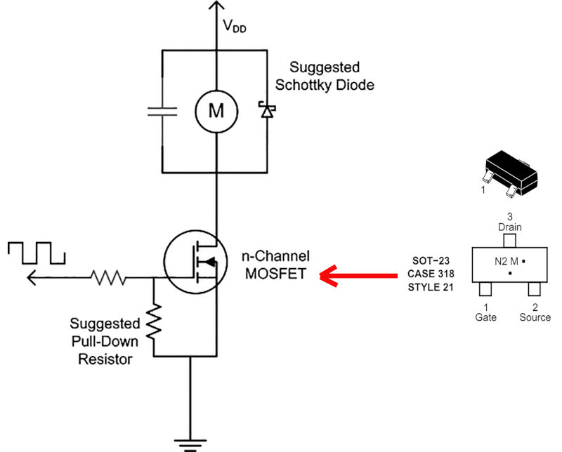
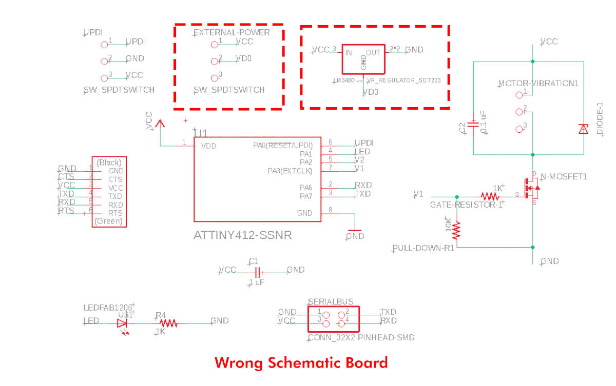
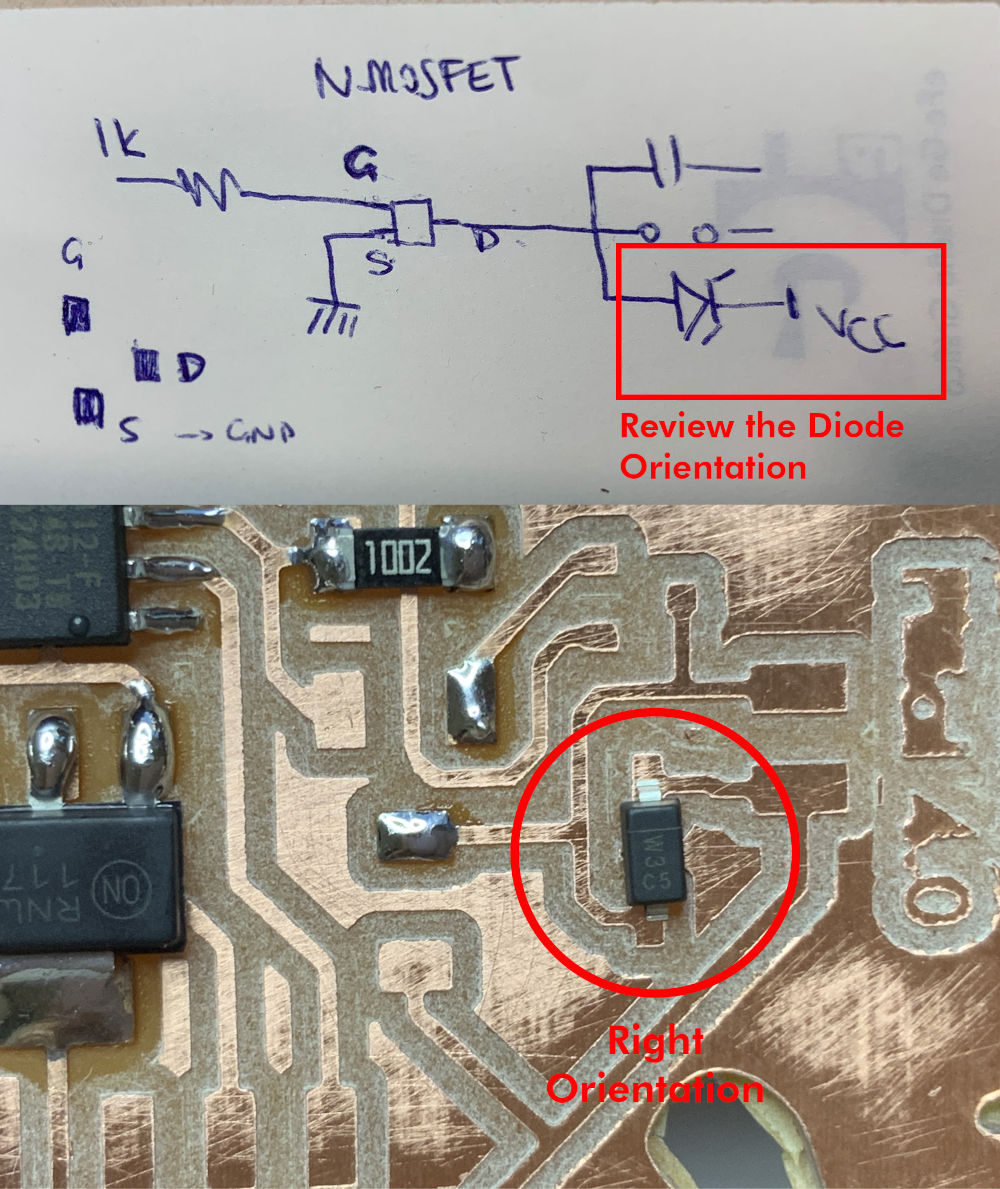
For this assignment, I have relied on the documentation of Victoria Peredo, who has followed this tutorial on how to make a circuit with a vibration motor using an n-Chanel Mosfet with a Pull-down resistor and a gate resistor.
There are two types of Mosfet, one with a p- Channel and the other with a n-Channel. The p-channel Mosfets work better in motors with a voltage lower than or equal to 1.5V, while the n-Chanel Mosfets work better in voltages of 2V or higher, because they tend to have a higher VGS gate firing voltage. N-channel MOSFETs generally have a lower turn-on resistance, and therefore where there is enough drive voltage to make sure you place the MOSFET in the saturated region, it will be more efficient. So I will be using this type on my new board.
In this circuit, the 0.1 uF capacitor reduces noise, it is not mandatory to use it, but it is advisable to place it near the motor terminals. The flyback diode protects the mosfet against voltage spikes. And the pull down resistor and gate resistor are recommended to be used to keep the Mosfet completely off when the active signal is not present. So we will use resistors between 1KΩ and 10KΩ.
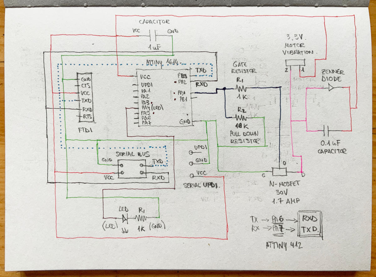
At first moment, I thought to use the ATtiny1614 for this new board again, this is the schematic that I designed...
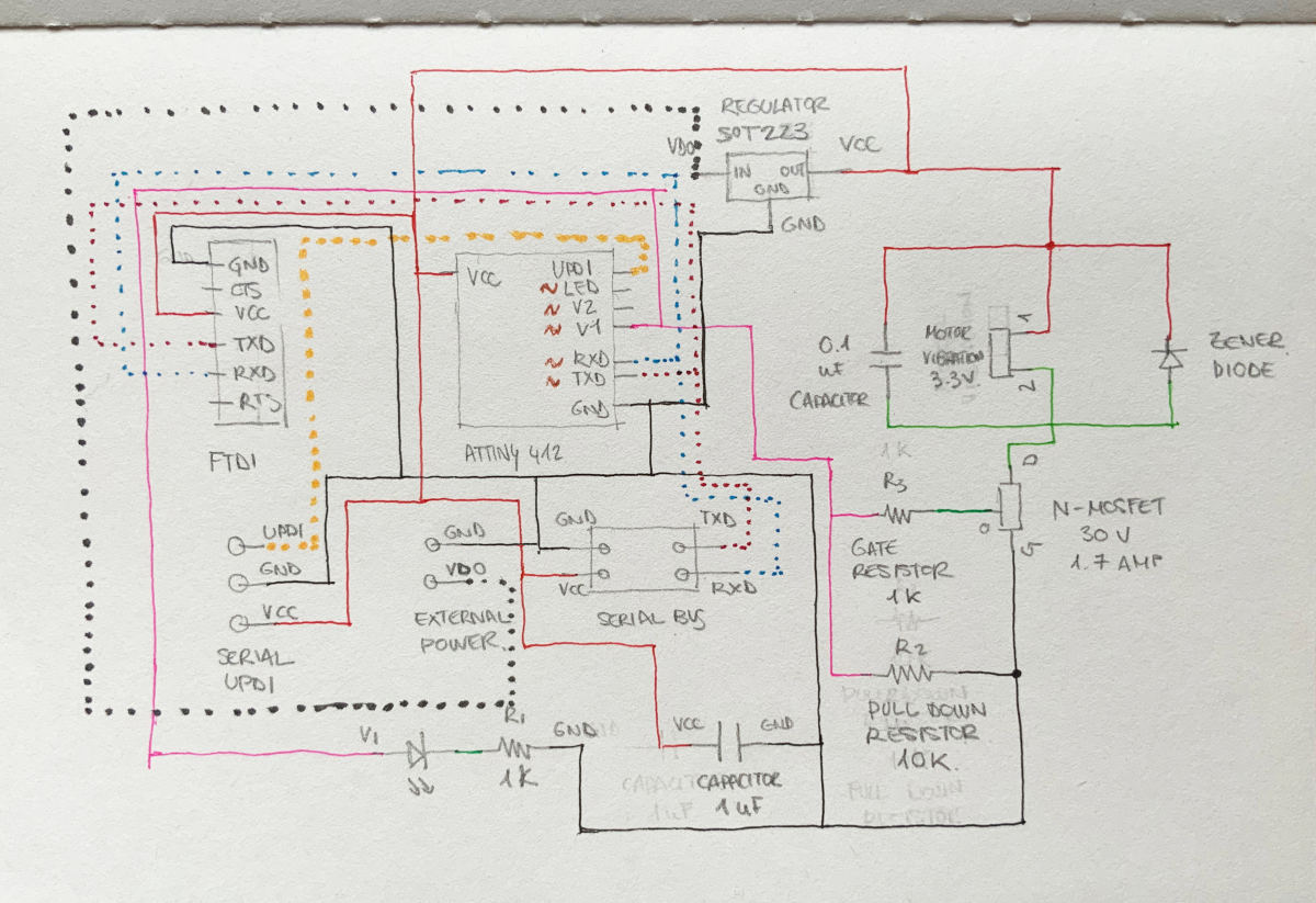
But seeing I was not going to need so many pins or capacity, I have decided to try with another new microcontrollers, the ATtiny 412 (Datasheet).
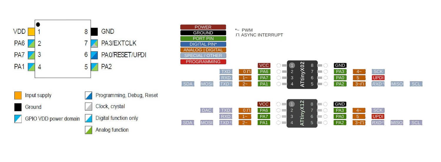
So, (as I usually do with each new board) I draw in my notebook the circuit I am going to make, integrating the Serial Bus that Adrián recommended to us for the week of Netowrking and Communications. About the new microcontrollers and future UART communication we do, Adrián warned us we have to swap the TXD pins for RXD and vice versa, following Neil's schematics for the following weeks.
So, reviewing the microcontroller datasheet, I keep it in mind to do the pin swapping when designing the board in Eagle.
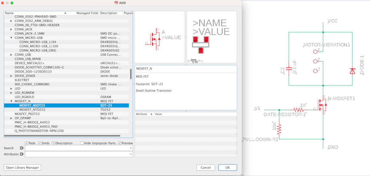
Once at Eagle, first, I designed the vibration motor circuit. Regarding the new microcontroller, as in the Attiny 1614, I have to re-download the footprint of the new ATtiny 412 from Octopart Page, and following the same instructions that I made for the Attiny 1614 at Input Devices week, to modify the outline and pins of the footprint .
On the other hand, according to some web pages and from what was discussed with Mickaël, to work with a vibration motor it is advisable to power the motors with external batteries from 9V to 12V. So, in my new board I have to incorporate a 5V voltage regulator.
As I don't have regulators in my fab lab, Alberto has lent me some regulators IC REG LINEAR 5V 1A SOT223 from the fab lab UE Madrid 😘.
For the pins regulators, it is important! checking the Datasheet of the component to know how is the arrangement of its pins. This part you will understand later when you get to the section "Stupid mistakes you can make".
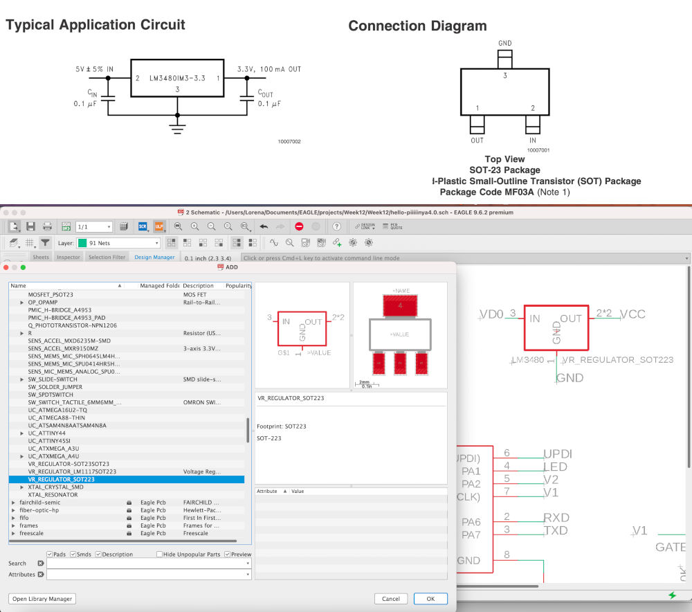
Finally, this is the schematic and footprint of my new board that I have designed in Eagle.
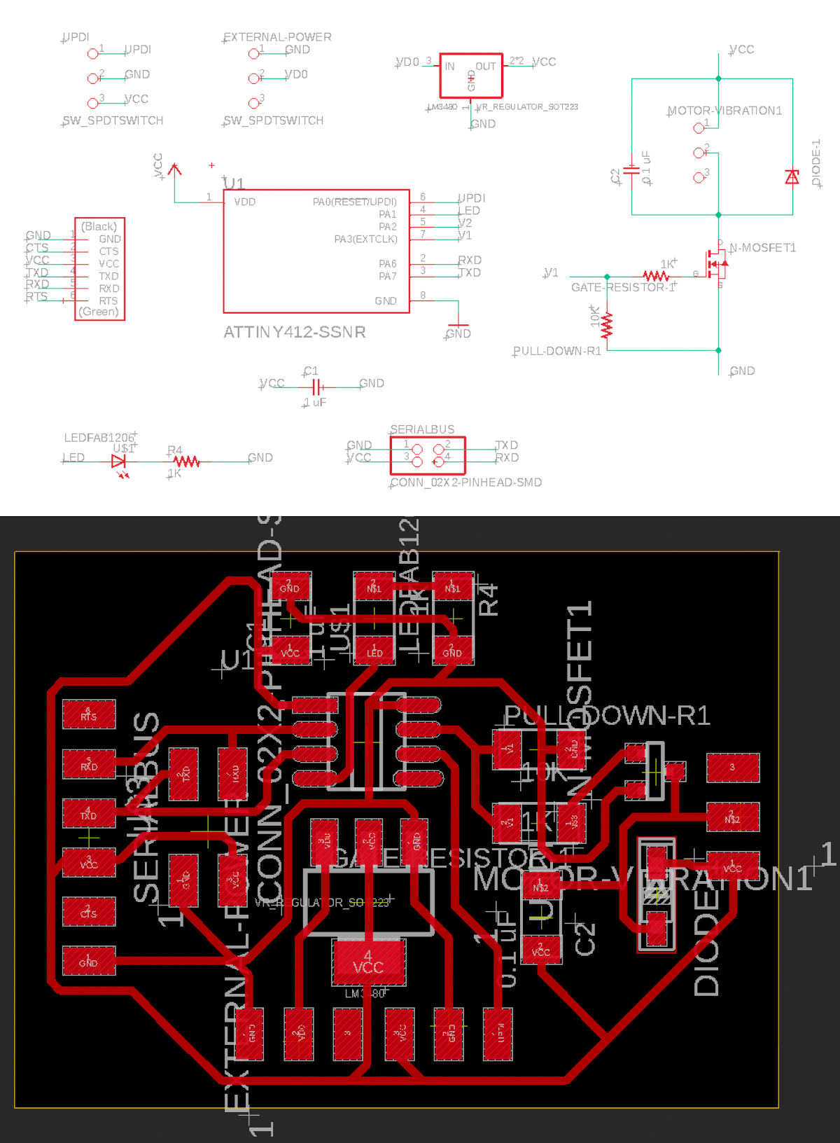
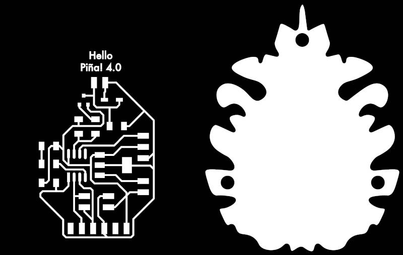
I export the path in a .png, and as is tradition, adapted the outline in Illustrator, to make the new Hello Piña! 4.0. These are the files of Hello Piña! 4.0 Traces. PNG + Hello Piña! 4.0 Outlines. PNG .
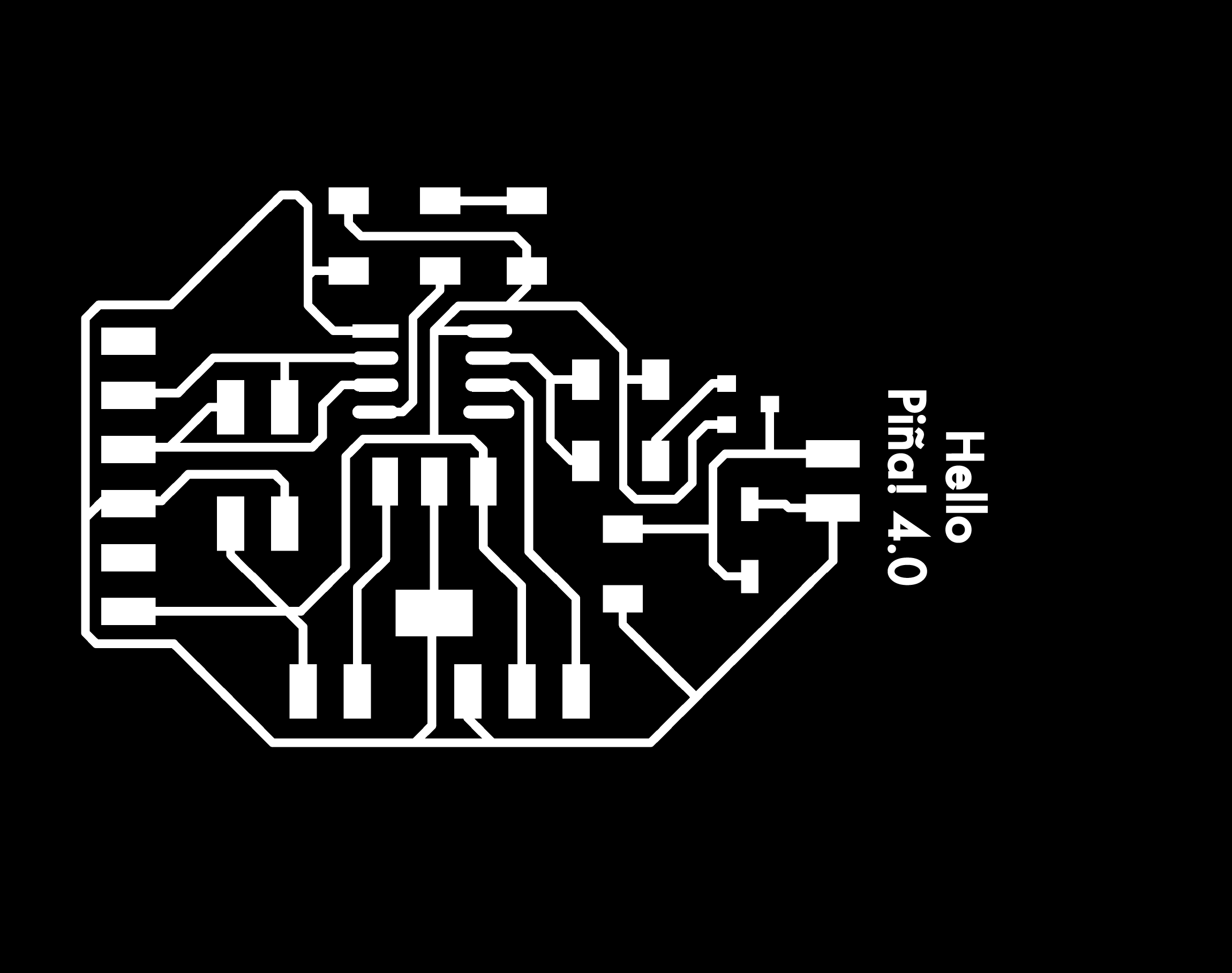
-
_ MILLING AND SOLDERING THE BOARD
(24/04/2021 09:37 a.m.) One more Saturday at Fab Lab UE Madrid with my dear crewmate Alberto, I am going to mill the new Hello Piña 4.0!
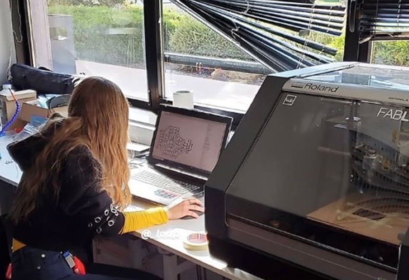
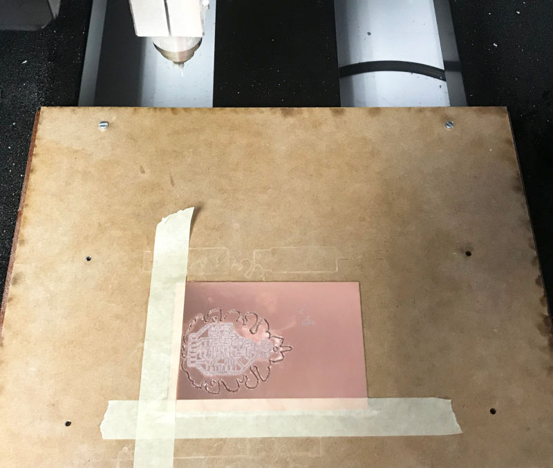
Here you can watch a short video milling the new PCB board:
And 45 minutes later, this is the result! 🤗
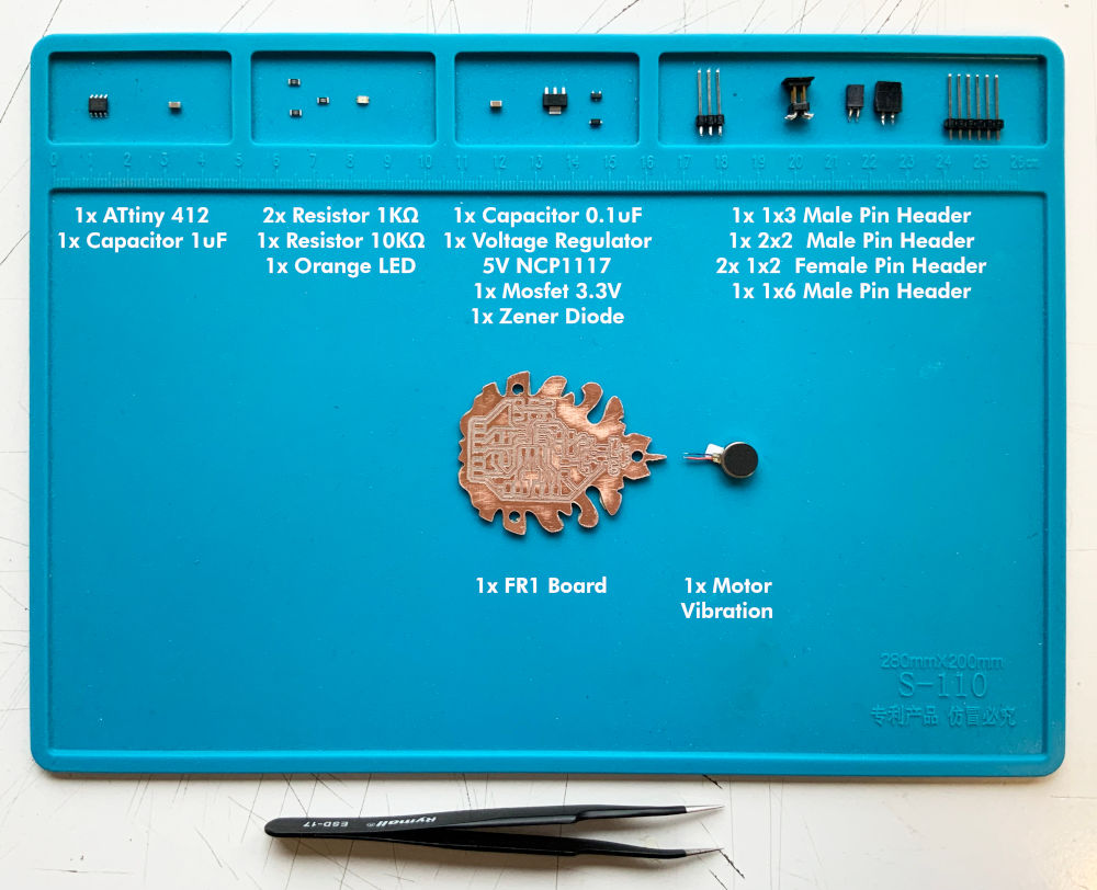
To solder the components of the new board, I need:
- 1x ATtiny412
- 1x 1uF Capacitor
- 2x 1KΩ resistors
- 1x 10kΩ resistors
- 1x orange LEDs
- 1x N-Mosfet 5.7 A 30 V SOT-23
- 1x Zener Diode
- 1x 0.1uF Capacitor
- 1x Regulator 5V NCP1117
- 1x 1x3 male pin header
- 1x 1x6 male pin header
- 1x 2x2 male pin header
- 2x 1x2 female pin header
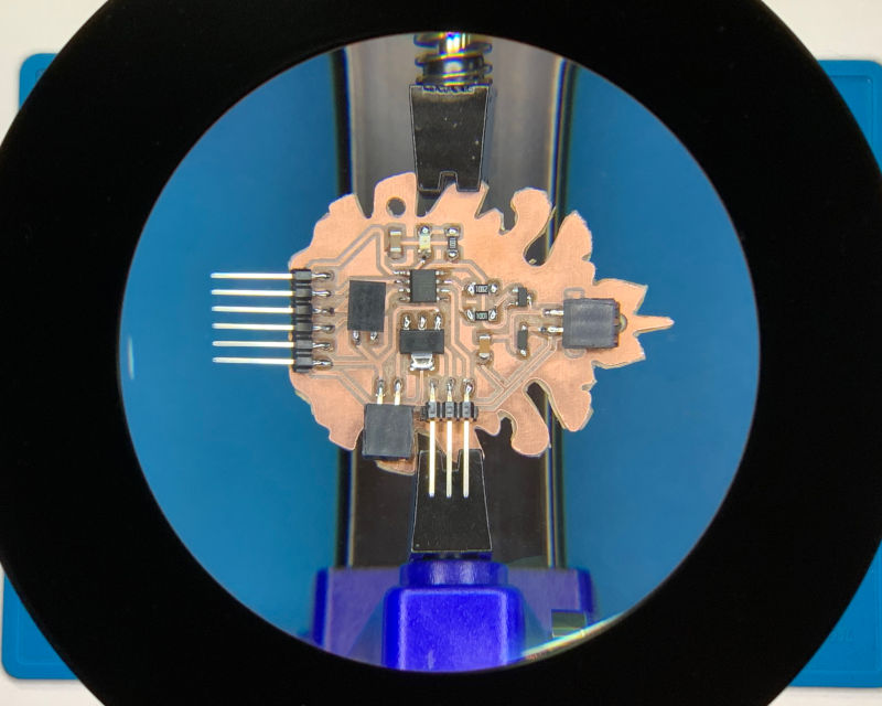
Here you can see a timeline where I am soldering the new board:
After an hour and a half soldering, this is the final result of the new Hello Piña! 4.0.
It seemed easy and simple, right?
Oh my dear, reader!. For now, here I have only told you how has been the correct process of my adventure with Hello Piña ! 4.0 and the vibration motor. In a few moments ... the dramas will come.
-
_ PROGRAMMING MOTOR VIBRATION CODE
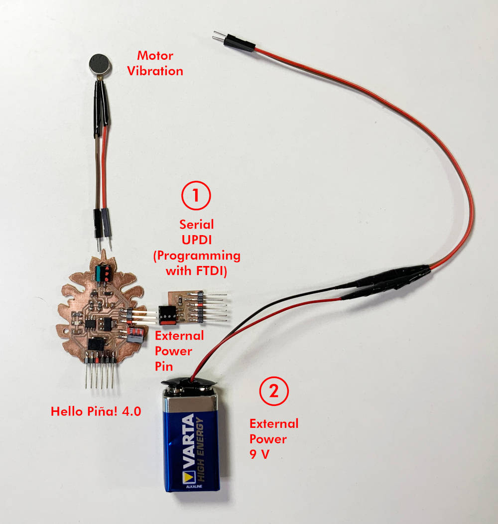
To program the new ATtiny 412 board, I will need again the Serial UPDI + VCC, which I milled and soldered at the Input Devices week. Once we have programmed the board, I will need an external 9V battery and the vibration motor (which we have soldered with some Dupont cables to better connect with the pins board.
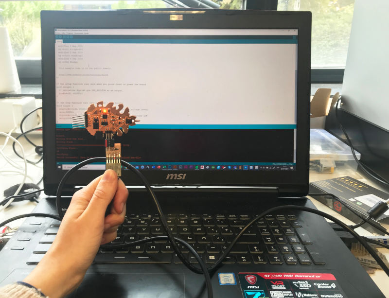
As on other occasions, the first thing I do is load a simple Blink code, to check the board works. On this occasion, seeing the problems arose during the Input Devices week I directly used my FTDI cable and I have "requisitioned" Alberto's laptop to program. 😬🤣
Without major problem, the Blink code has worked! 🎉🎉😍😍
Once I have verified the Hello Piña! 4.0 works, I am about to program a simple code for the vibration motor.
To do this, what I am going to do is add some time variables for the motor to vibrate and stop vibrating in a short period of time.
This is the final code:
// Lorena Delgado Piña, 2021 Fab Academy, Output devices week - Vibration Motor

int VibrationPin = 4; // create integer variable for motor pin on Attiny412 PWM PA3 pin
int onTime = 200;   // create integer variable for when motor is on
int offTime = 600;  // create integer variable for when motor is off

void setup() {
pinMode(VibrationPin, OUTPUT); // Set output on Attiny412 PWM PA3 pin

}

void loop() {
  // put your main code here, to run repeatedly:
digitalWrite(VibrationPin, HIGH); // turn vibration motor on
delay(onTime); // stays on for 200 ms
digitalWrite(VibrationPin, LOW); // turn vibration motor off
delay(offTime); //stays off for 600 ms
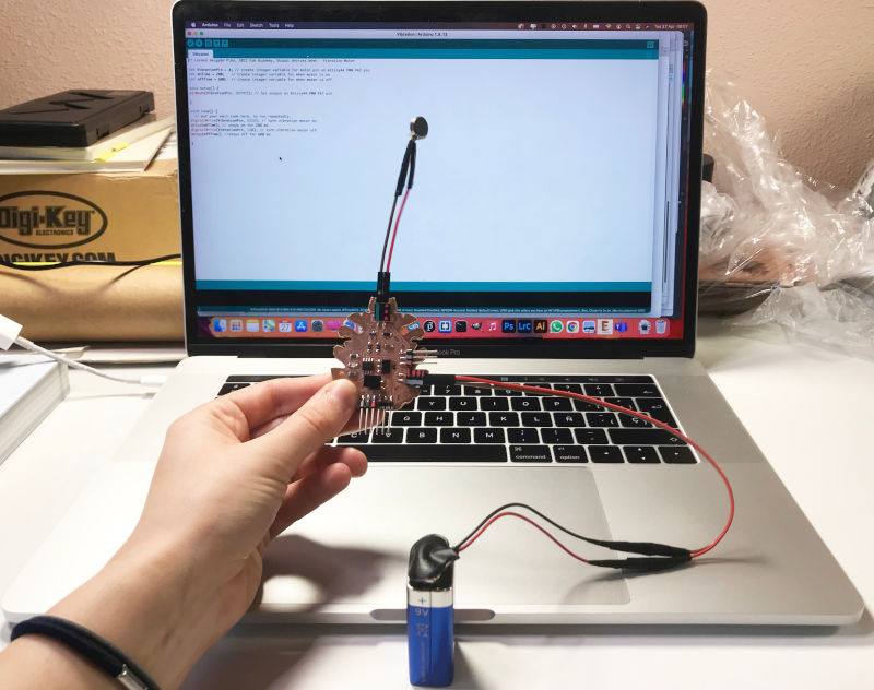
Once the code is loaded, I connect the battery first, and then the vibration motor. In this little video, you can see how I following this procedure, and the board works!! 😍😍😍
(27/04/2021 11:27 a.m.) During Tuesday morning, I met with my crewmate Mickäel, who had also worked with the vibration motors. And he told me, according to some webpages, that to disconnect the battery from the board, it is advisable with tweezers "unload" the Capacitor, and then remove the pins battery.
Here you can watch a short video, where I show (more or less, because my hand hides the process a bit) 😅, how I drain the capacitor and disconnect the battery:
"Stupid mistakes you can make" 😅😅
(28/04/2021 12:12 p.m.) Everything seemed very easy, right? Well.. I desagree!
The first part of my documentation was only the sweetened story of how was the correct process of design + soldier + programming of the Hello Piña! 4.0 with the vibration motor. But the reality is, until the same Monday 26th at night, I did not get my 4th HELLO PIÑA! BOARD it will work!!
Here I am going to tell you what have been the real dramas have happened to me throughout this week, the hidden things! or how the Spanish expression says ... "los entresijos".
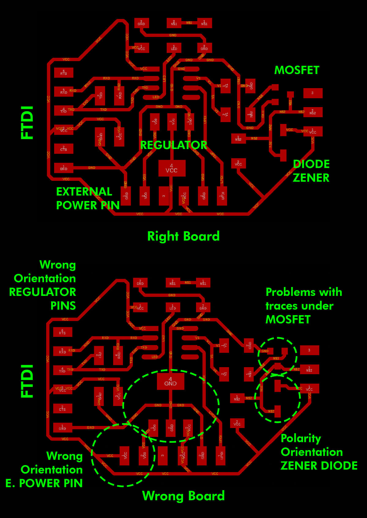
(24/04/2021 20:23 p.m.) On the one hand, during Saturday with Alberto, I had two principal problems in the schematic design of the board. First, I was connected GND battery pin with VCC of the microcontroller😳.
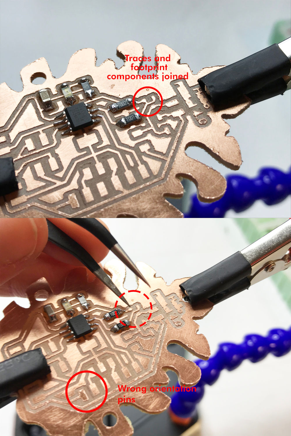
And to top it off, I was following the Adrianino´s schematic to know how to dispose the 5V Regulator pins, but I didn't realize that Mickaël and me were using different regulators than Adrián, so the pins arrangement were different in the schemetatic.
(26/04/2021 12:10 p.m.)However, as I was thoroughly analyzing the board, I found another series of mistakes that I had made, such as in the mosfet tracks.
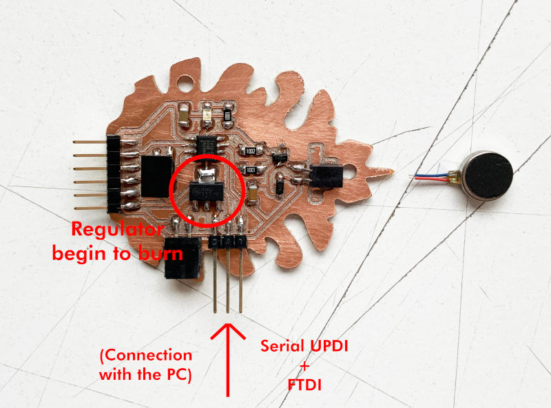
(25/04/2021 17:34 p.m.)In the first and second Hello Piña! 4.0, at the moment I connected the Serial UPDI + VCC with the computer to my board, the 5V regulator was starting to smoke 🔥, and the board was completely dead 😵😵.
At the third Hello Piña! 4.0, the Roland MDX-400 had not milled the traces well on N-mosfet, because I was passing a track underneath. So, at the moment I soldered the pins to the board, it had continuity between the different pins. So I had to separate the tracks by hand with a cutter.
However, although the third Hello Piña! 4.0 I was able to program a blink code 🎉, when I programmed the vibration motor code, and connected the battery to the board, the diode Zener started to burn 🔥🔥🔥 (and my head too ) 🤯.
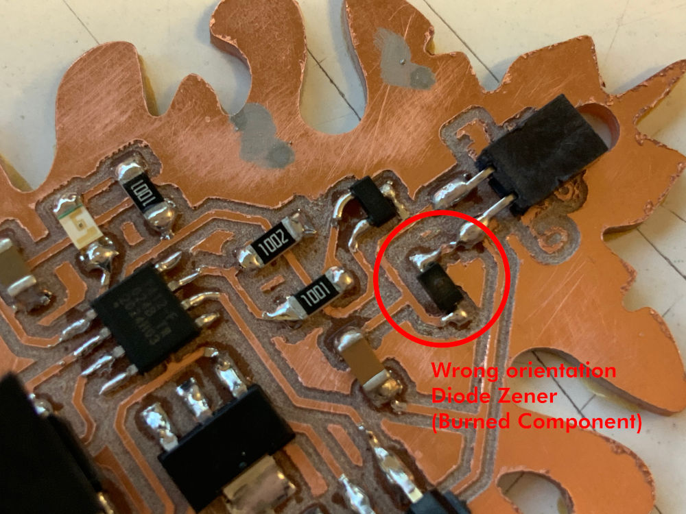
(26/04/2021 17:47 p.m.) I didn't know what was happening!, so I reported the problem to Adrián + Nuria + Pablo. Adrián and Nuria told me that I would check the polarity and orientation of the Diode Zener on my board, because it would be probably soldering it backwards. And indeed, it was!
I was soldering the zener diode backwards, and as soon as I plugged in the battery, the diode started to smoke! ⚡⚡.
My face of despair from Saturday to Tuesday afternoon was this! I had slight moments when I really wanted to cry 😭, but thanks to my crewmate and great friend Alberto 💚, I went ahead and he sent me subliminal messages of support from his OLED screens 💖.
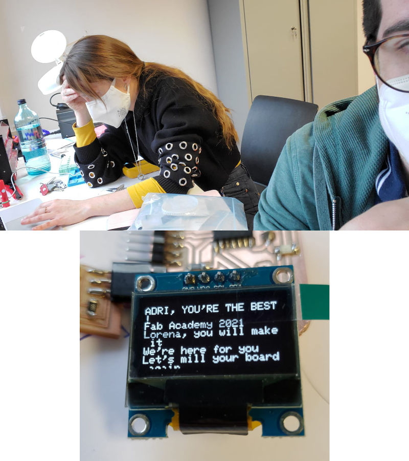
(26/04/2021 21:28 p.m.)On Monday night, Alberto recorded the moment of victory, when after a week of chain errors, I finally got the Hello Piña! 4.0 with the vibration motor WILL WORK! 🎉🎉🎉
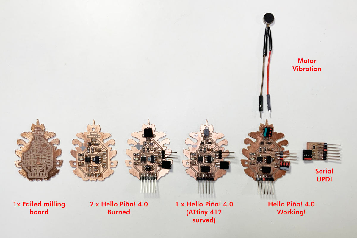
SUMMARY
Finally, referring to my favorite Disney movie (The Lion King), I show you the count of the Elephant Cemetery: 3 x Hello Piña! wrong boards, 2 x Hello Piña! dead, 1x Hello Piña! dying, and a Hello Piña! 4.0 survivor.
FILES
HELLO PIÑA! 4.0 MOTOR VIBRATION
PROGRAMMING MOTOR VIBRATION CODE
REFERENCES