Electronics Design
Hello fab friends and welcome to the 7th assignment of my FabAcademy. This was a very weird week for me, as I had never done this before, but I surely enjoyed to finally learn the basics of the electronics design, working with a new software but remembering the old concepts I learnt in primary school. The main problem was that, last wednesday I didn't even know what a hello board was,, but thanks to a little bit of help of my friends, I managed to have a hello board relatively easily. First hat tip goes to FabAcademy graduated and great friend of mine Alejandro Ulecia, as he came to my FabLab on Saturday to help us with the assignment. Also, my best advice to following year's students is learn how things actually work before designing anything.
Chapter One: Group Assignment, one multimeter to rule them all
As we did with the FabISP construction two weeks ago, the multimeter was proved very handy to check the continuity of the tracks or the polarity of the LEDs, but in this week's assignment, it also helped us decypher the functioning of the button. Why does it have phisically four pins but effectively only two? Checking the continuity of the button with it and without it pushed helped us learning how it works internally, and it was key to design later. If you speak Spanish, I really recommend this tutorial by Adrián Torres.
In Universidad Europea there is an electronics lab, but in our FabLab we have a little multimeter. Here you can see our classmate Lorena using it
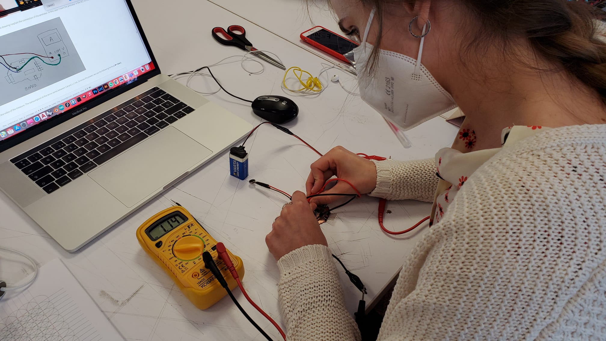
We basically use it to measure the continuity of the traces, and check the polarity of the LEDs. In order to do that, place the multimeter's dial in the LED position, and if you touch the red end on the positive side and the black end on the negative side, the LED should light. If you do it the other way round, the LED should not light. For continuity, the multimeter beeps.
Chapter Two: When in Design, do like Designers.
There's a say in English, "When in Rome, do like Romans", or in Spanish "Donde fueres, haz lo que vieres". Facing this assignment, I had absolutely no idea about electronics design, but I knew some design methodology. So, How do I start to design when I design? Exactly. I start with a blank piece of paper. For me it was the number one rule in Electronics Design. It's impossible to start designing anything in Eagle or KiCad if you don't have an idea of what it's going to look like, or act like, or do. So the best idea we could have was, drawing all the components in a paper, with all the pins, naming the pins, and knowing what does what, and what connects where, is the key to success.
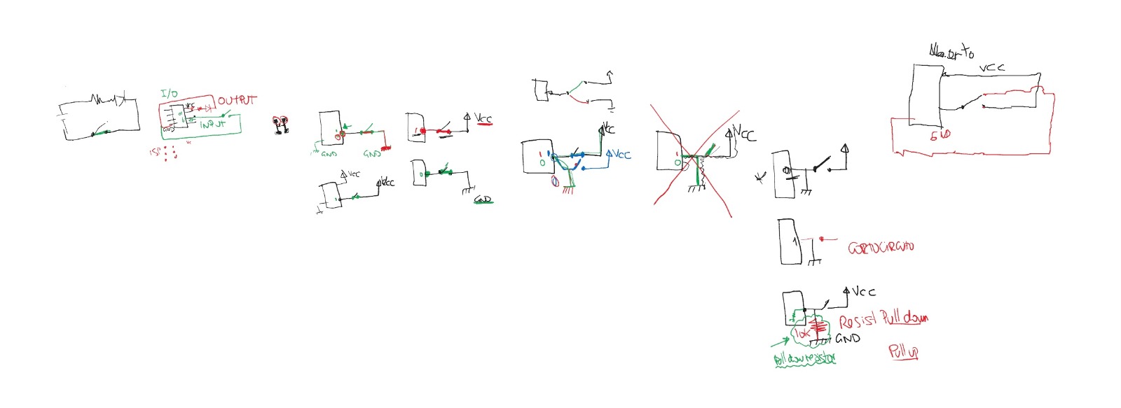
In our local lesson, Nuria, Adrián and Pablo gave us the basic explanations on how the things worked or not, but now it was time to design from scratch. I decided to redraw what Alejandro explained to me, naming every single track of my circuit, and understanding where was it going to redirect, and to do what. To understand the pinout of the microcontroller that I was going to use, what I needed to read from each pin, and what I needed to "push" on the outputs to achieve the desired goal.
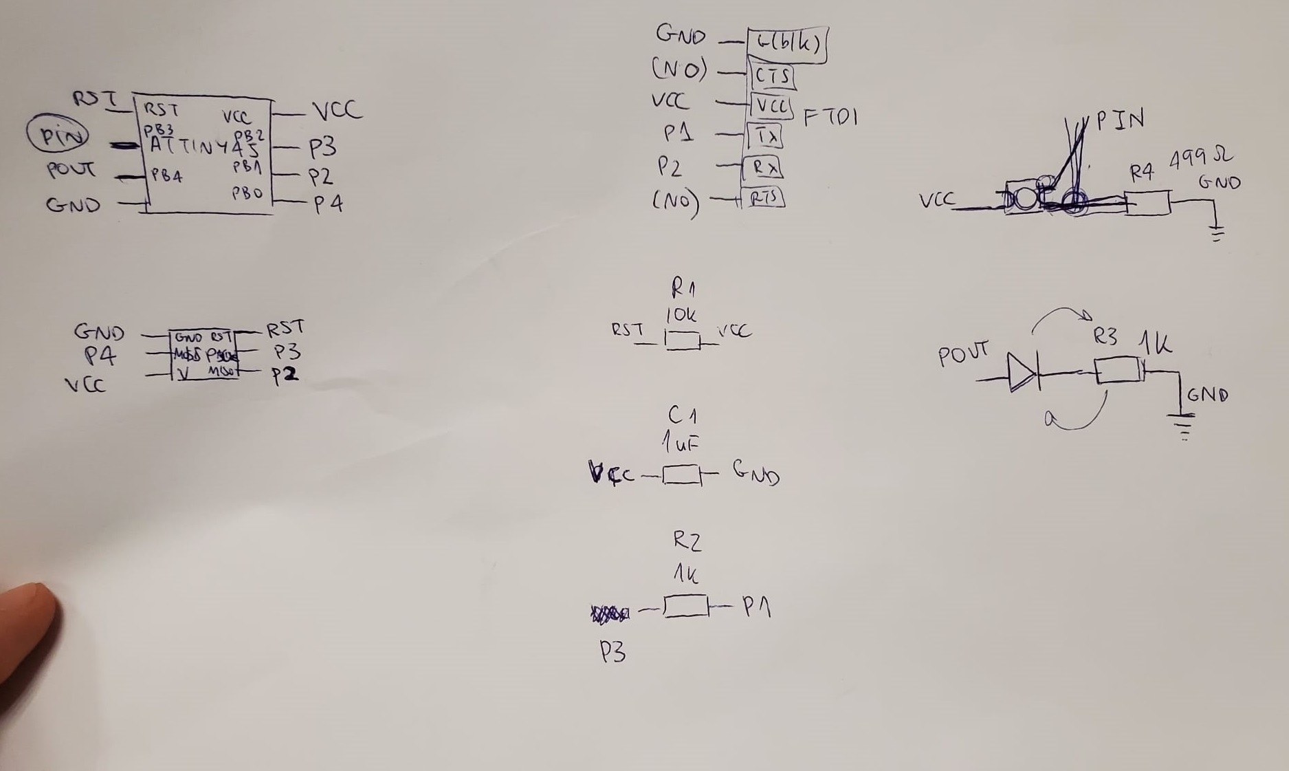
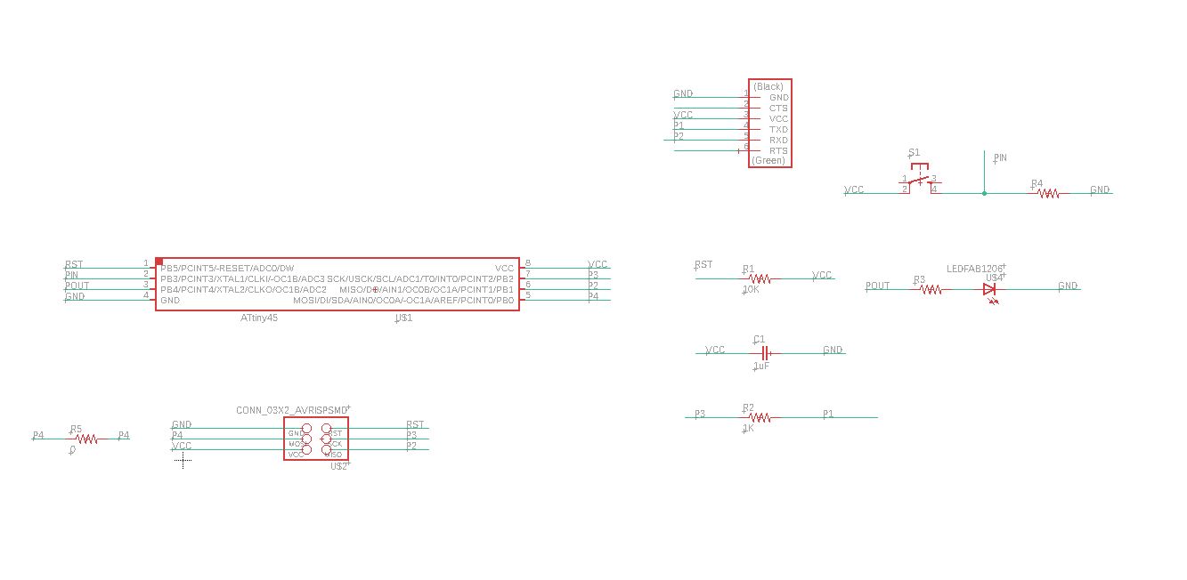
I decided to design on Eagle. The workflow I used is as follows: first I do a list of the components on a piece of paper and I check the connections, then I open a new schematic and I start to place the components on it, starting from the microcontroller, then LEDs and resistors, and finally the connectors. Then I change to board design, and with the 16 points width trace (or 20 if I have space). Then I deactivate all the layers except for the first one and I export the Board as an image, in monochrome, at 1.000 ppp in order for it to fit the standards of the FabModules procedure.
I started installing the libraries following Nuria's tutorial. Then I started to lay down and lable the components. I had to add a jumper, a 0 Ohm resistor to be able to make my board's connection reach their goals.
After the schematics, it was time to design the traces, the actual board. Here I had my first head bang. This error message kept appearing on the screen:
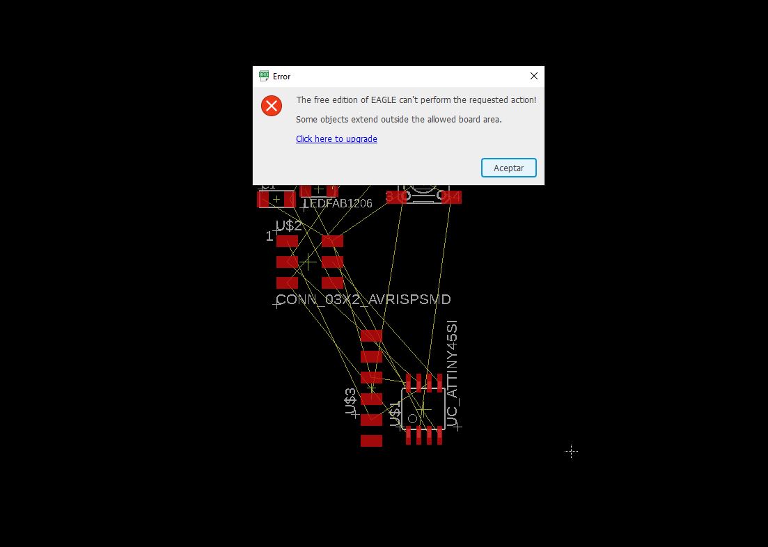
This was caused by having the wrong email on my Autodesk account, as I downloaded the Eagle software with another Autodesk account, and not the one associated with the mail I have on my FabAcademy. So, correct account in, and here we go.
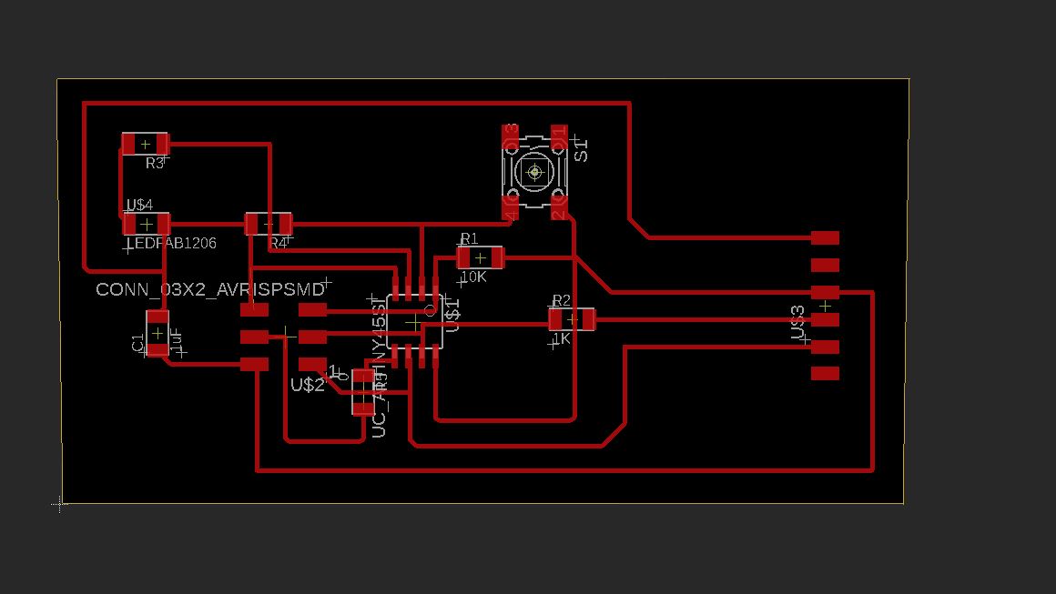
I will never forget my FabAcademy classmate Sergio Herranz, when he came to the FabLab that saturday, he got baffled by the horrendous design of those paths, and he said to me "man that's an ugly board, and it looks that you have a short circuit! It's not going to work", as the design is of course confusing and ugly. But I was confident in myself, I knew the tracks were properly named and then connected.
Chapter Three: Shiny and smooth
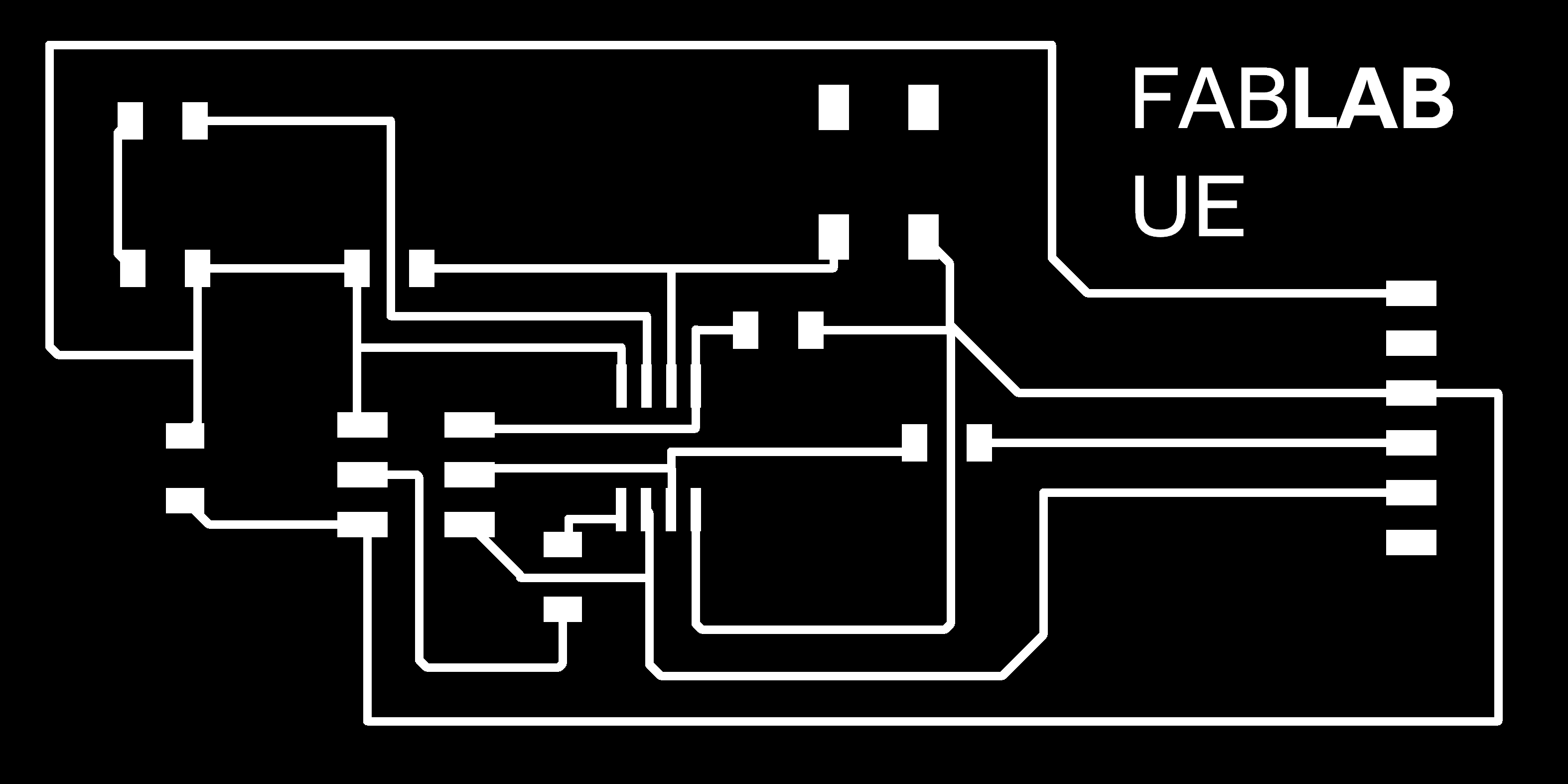
I exported the traces (file - export - Image), in PNG and in black and white and then I heard my friends laugh behind me as they watched me adding my FabLab script using Microsoft Paint. I was just doing a test. I was not going to mill that board... Or was I?
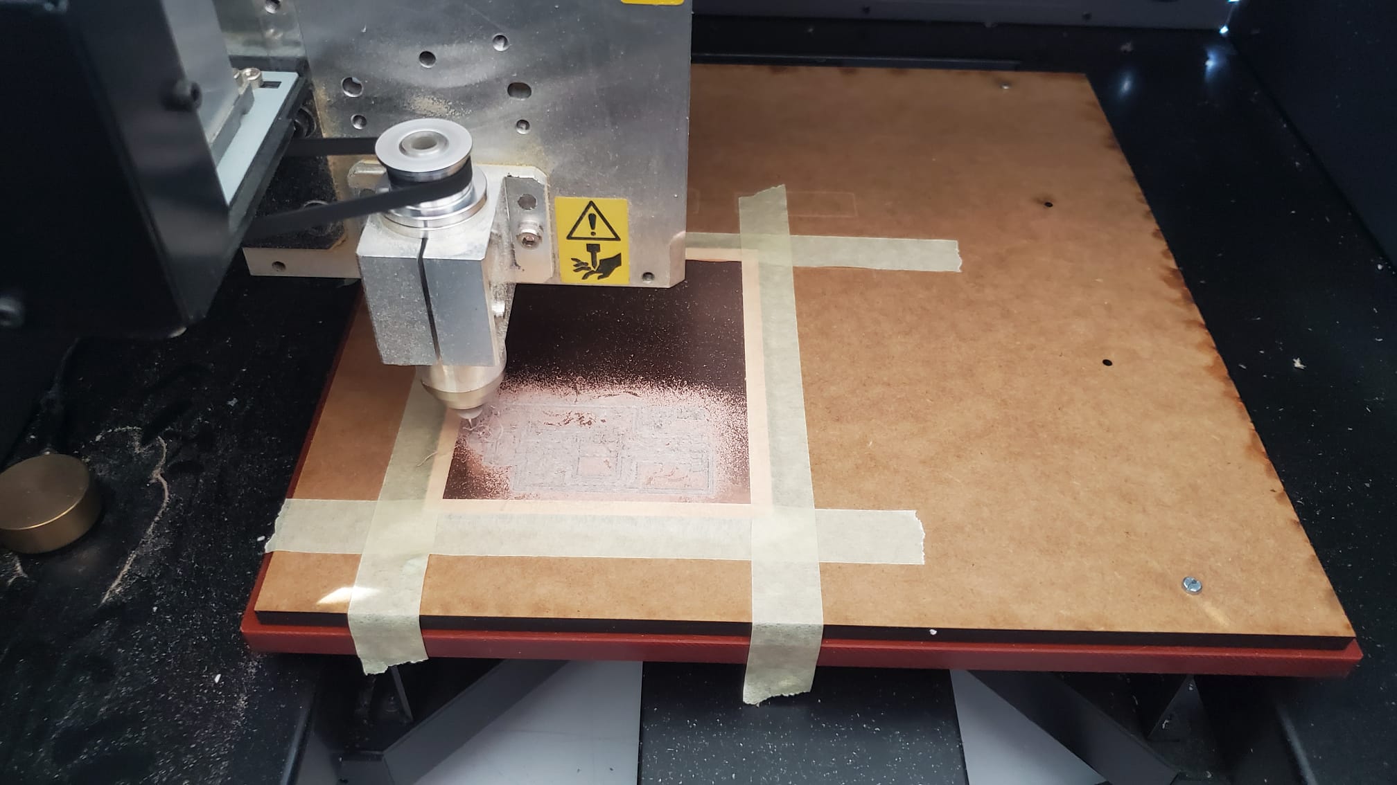
I decided to do a quick test to check if everything worked, and also to have something to practice soldering before going back to solder "the correct board", So I went to mill the board with our Roland MDX-40A and I quickly realized that it was too big and too ugly to be worth being presented. But then I realized. "If my Voltera fails made Neil smile, this process is also worth to be carried over. Let's see how hard I fail with this one".
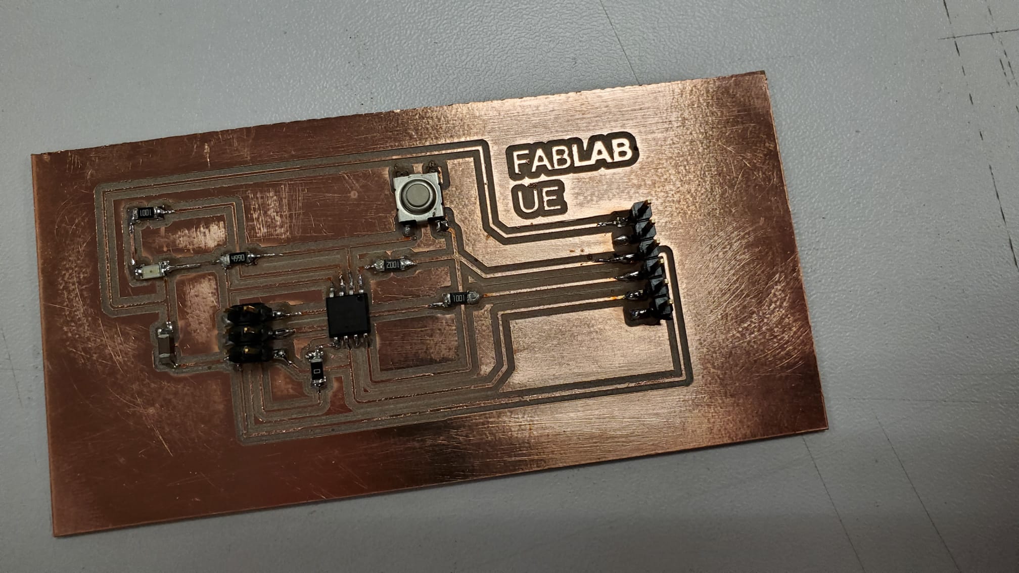
Chapter Four: It's not an ugly board if it actually works
It was now time to check if it worked. Yeah Sergio, it did! So what do you do when you have a completed board, a FabISP programmer, a computer with Arduino and a FabAcademy graduated friend in your FabLab, it's saturday evening and it's getting late? Do you go to the bar? No! Of course you program the damn thing!
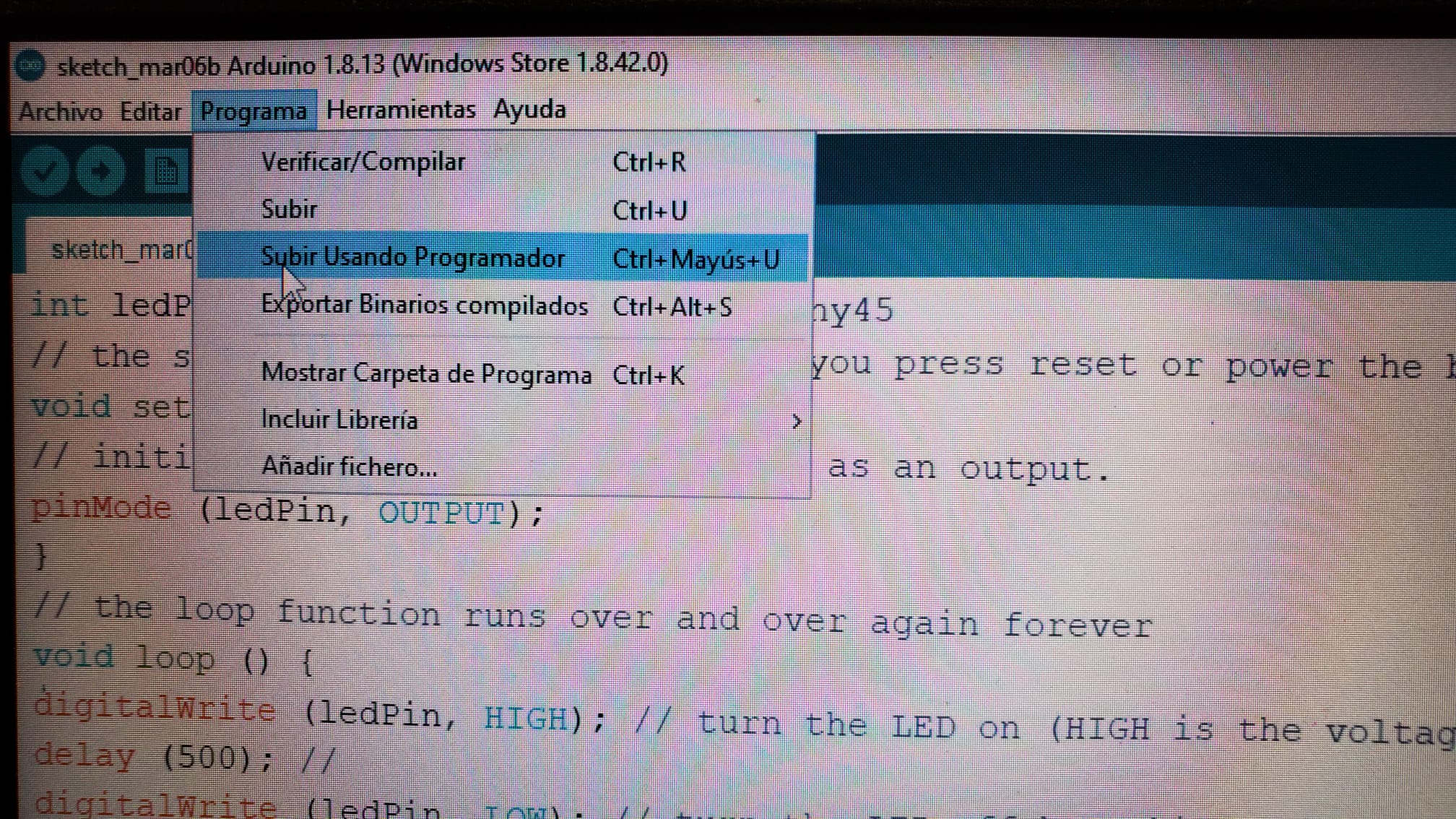
I followed Alejandro's tutorial, but there's a thing he forgot to mention. When you're sending the program to the hello board, you should not just send it with the Arduino IDE pressing send. You have to click on upload using programmer, otherwise it will send an error message like this: avrdude: ser_open(): can't open device "\\.\COM4": El sistema no puede encontrar el archivo especificado.
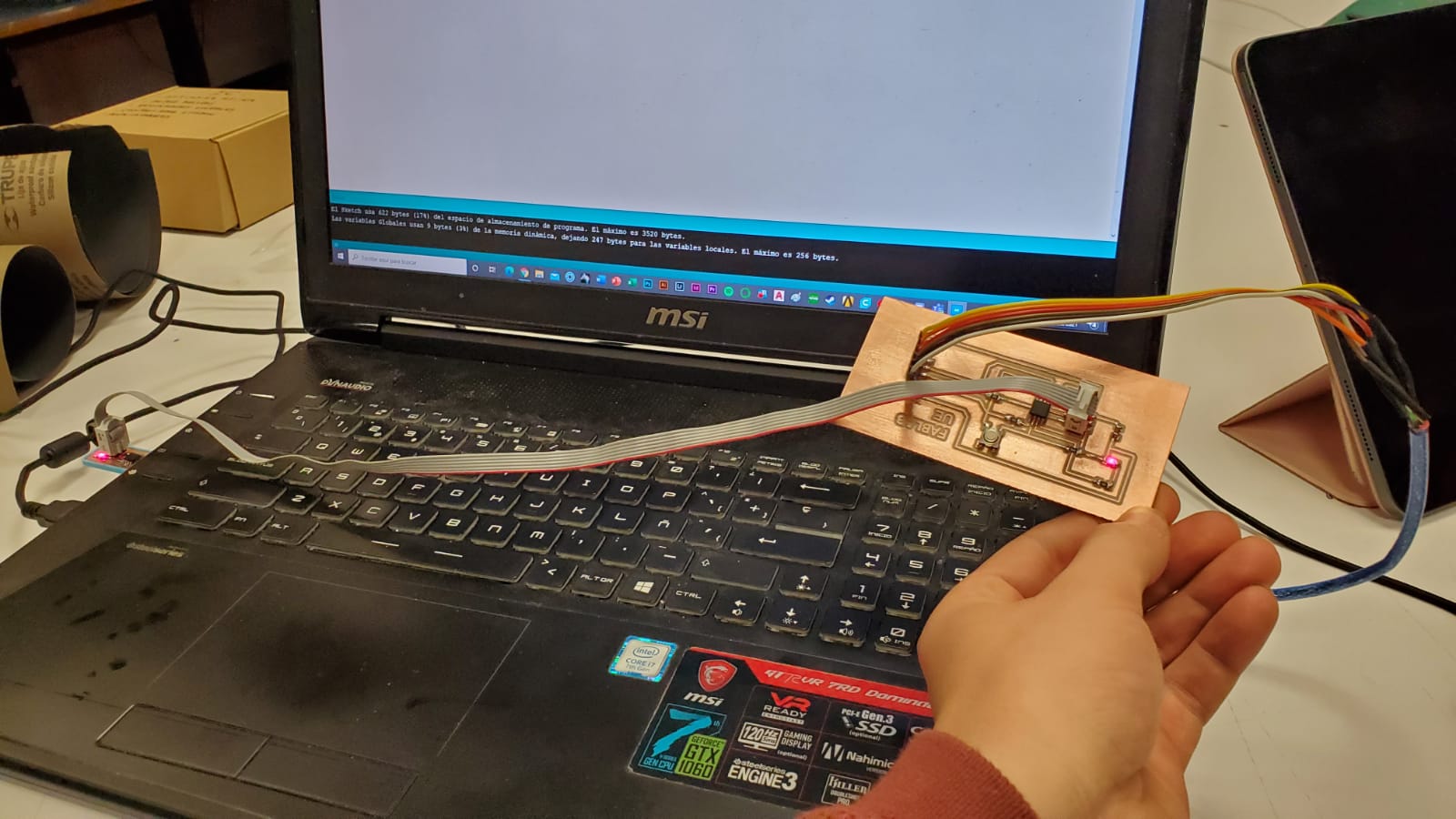
But by sending the program through the programmer, it worked! When I press the button, the LED works. I can make it stay whatever time I want it to stay, or I can make it blink the number of times I want. So this assignment is apparently completed.
This is the code that works with my board.
You can get the Eagle board file HERE.
You can get the Eagle schematic file HERE.
Chapter Five: Triage
My problem with this assignment was time. Couldn't make something beautiful on timeI had an idea of a board, but I needed to use more outputs. So I began studying Adrián's page and I loved his idea of a train! I wanted to make something like it, but I realized some of the components were missing. I had the opportunity to use an AtTiny44 or an AtTiny 1614, I started to check the fantastic possibilities that I had with a microcontroller with more pins. And then everything went upside down. I even have to give the town's mayor a FabLab tour
I gave this assignment a call back on the embeded programming week . If you want to see if that week I could mill and program another board, check that page out! See you soon!