13. Output devices
The assignment for this week was to add output devices to an electronic board that we made. For me it’s the direct following of the assignment from two weeks ago 11. Input devices.
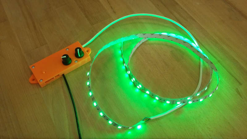
The project
As you already know the project is to control a RGB LED strip. But to do so we can’t just connect it to a microcontroller, because the LED strip need more power than the microcontroller. But don’t worry, there always a solution. In this case, a mosfet will do the trick. To explain it simply, a mosfet is like a switch on the power circuit but it’s activated by the microcontroller. Thanks to this component, we can separate the intelligence part from the power.
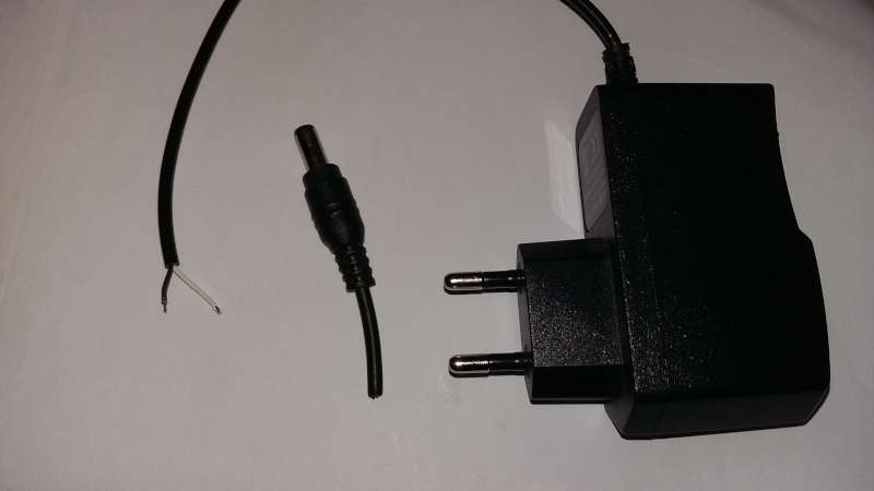
Before continuing, we have something else to think about. On our board, we have an Attiny1614 which need 5V and the LEDs which need 12V. But I don’t want to have several power supply. So we will only keep the 12V supply and transform it to obtain 5V. The components doing this are called regulators.
The board
It is the exact same board as the one presented two weeks ago from the assignment input devices. To make it, you will need the following library and components.
Eagle’s library :
List of components :
-
Attiny1614
-
SW_SWITCH_TACTILE_6MM
-
R1206FAB
-
CAP_UNPOLARIZEDFAB
-
VR_REGULATOR-SOT23
-
MOSFET_NSOT23 (MOSFET_N)
-
CONN_04SMD_RA_MALE
-
CONN_02SMD_RA_MALE
This is the whole schematic :
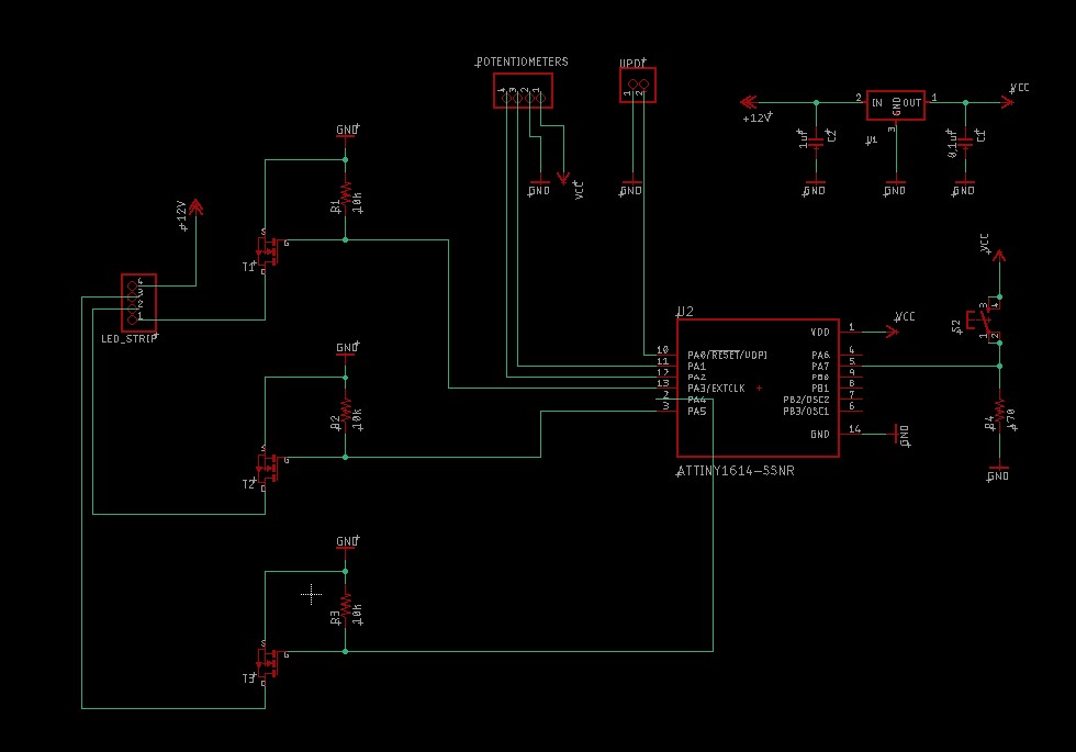
There is several different parts to this schematic. On the top right corner you can find the regulator circuit with two capacitors to protect and suppress noise. And on the left, you can see three N-mosfet for each LED.
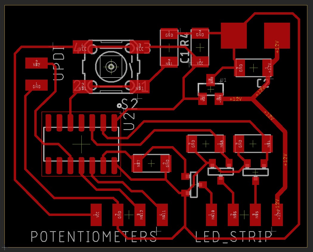
After routing, the board look like that :
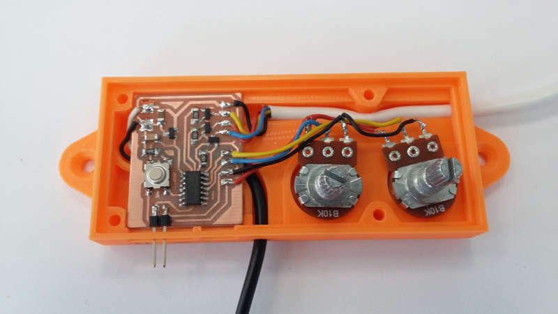
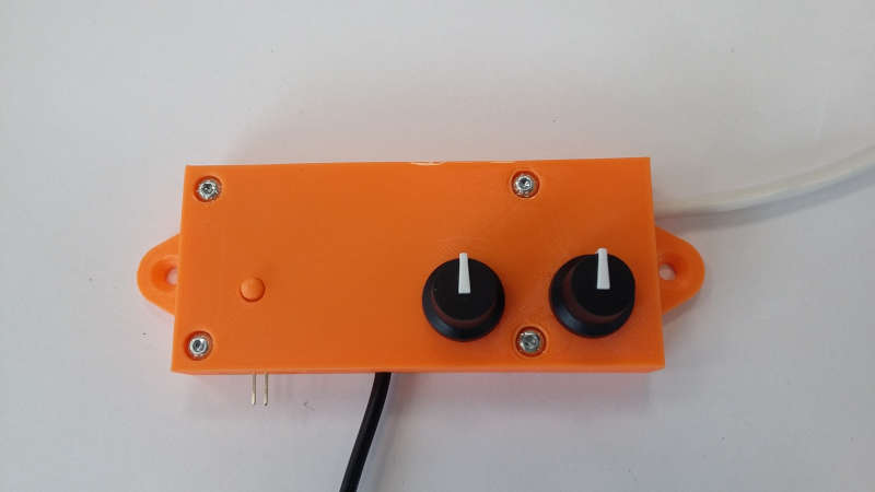
Case design
Then I designed a box to hide the electronics. To create this box I link my board to Fusion360 and find the step file of my potentiometer on Grabcad. After that I had every dimension I needed to know, and made my box directly around my components.
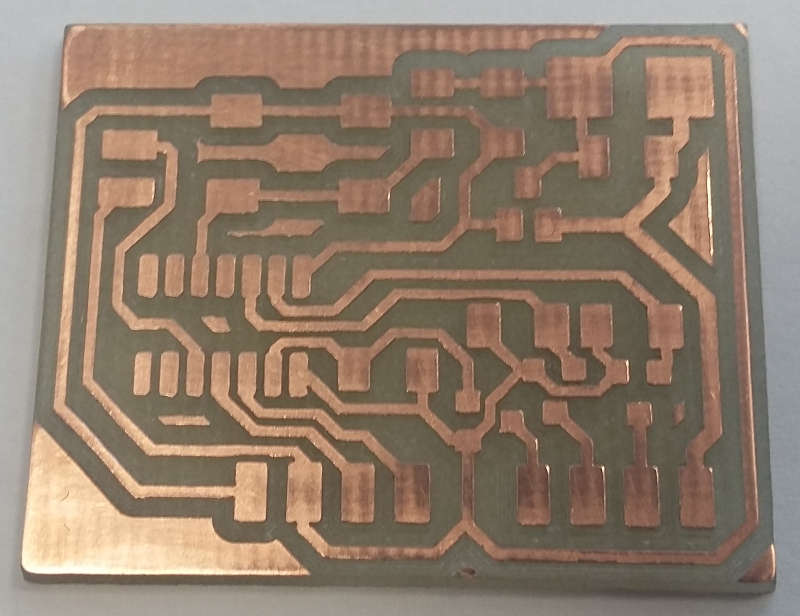
Manufacture
Programming
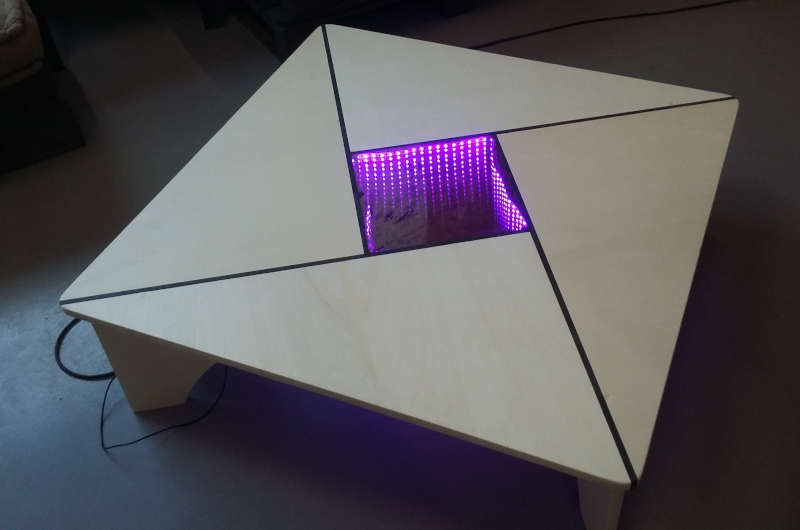
The coffee table
Mistakes
For my first board I did the same thing as the electronics design week. I added a +5V to the UPDI to be able to program it only by connecting it to my computer. But it isn’t the same configuration since I also have a 5V regulator. So when I connected my second supply via USB/UPDI, the current was going through the regulator in the wrong way and burned it out. However, it wasn’t instantaneous and took some time, at the beginning it was working perfectly. So when the incident happened I did not understand what was going on.