11. Input devices
This week’s assignment was to go further into electronics by adding input devices to a microcontroller. However, I didn’t stop there and also add some output devices. I didn’t explain this second part on this page since we are supposed to do this in two weeks. So if you are interested in output devices I invite you to go on my assignment 13. Output devices.
The project
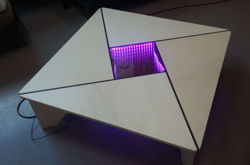
As you know, three weeks ago I made a coffee table and I planned to add an infinity mirror at the center but I never had the time to do this. So I devoted this week to complete this project.
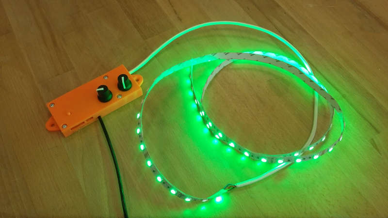
The idea is to be able to control a RGB LED strip to choose a color fitting your mood or interior decoration. I will also add an automatic mod that will progressively change the colors following the chromatic circle.
To interact with the electronics, I will use potentiometers(input devices) to change colors and a simple switch to change mod.
RGB principles
A RGB LED is actually made of three monochrome LEDs which can be controlled individually. If you only switch them on or off, you already have 8 combinations as described by the diagram below (the eighth combination is when the three LEDs are off).
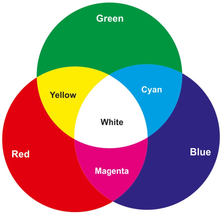
However, you can also light a LED progressively by using PWM. By doing that you will be able to obtain any color between the mains colors shown above.
In the Arduino IDE, we have a library to easily use PWM by putting a value between 0-255. We will begin simply by only changing colors that share a border on the diagram (and without white), which means that we will command only one LED at the time. But even doing that we have 6 borders with 256 positions, so 1536 positions in total.
On the other hand, the input potentiometer will be connected to an analog pin that will return a value between 0-1023. So if we convert directly the position of the potentiometer to a position on the chromatic circle, we will miss some step. Moreover, if we want to go further by adding white or going from a color to another that doesn’t share a border, we miss even more steps.
My solution, I will use two potentiometers. The first will command 7 main colors and the second will operate the 256 positions in between. Both values are inferior to 1024 so we won’t miss any step.
The board
The first thing to do is analyse what we need to properly choose our components.
For the input I have two potentiometers and a switch, so I need three pins. For the output I need three PWM pins to control the RGB LED strip. Like the previous I’m also planning to program my board via UPDI.
After checking the microcontroller that I have at my disposal, I choose to use a Attiny1614.
Then I checked Eagle’s library and of course the Attiny1614 wasn’t in any of them so I’m sharing it here with the Fabacademy’s library and design rules :
Now let’s do the schematic, this is the list of every components :
-
Attiny1614
-
SW_SWITCH_TACTILE_6MM
-
R1206FAB
-
CAP_UNPOLARIZEDFAB
-
VR_REGULATOR-SOT23
-
MOSFET_NSOT23 (MOSFET_N)
-
CONN_04SMD_RA_MALE
-
CONN_02SMD_RA_MALE
You can then connect everything like I did in my schematic below :
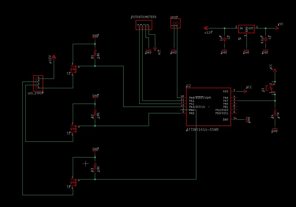
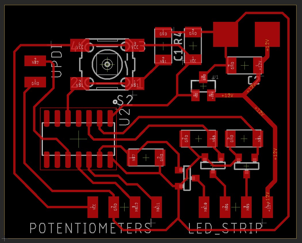
When it’s done, go to the board environment, place your component and ask the autorouter to do its job. It’s possible you have to tweak around to complete the results of the autorouter.
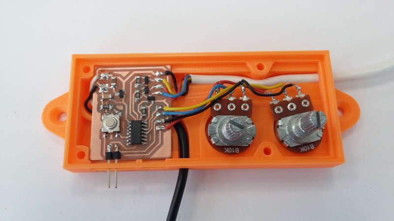
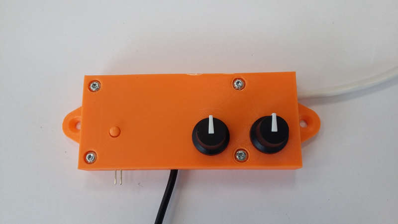
Case design
Then I designed a box to hide the electronics. To create this box I link my board to Fusion360 and find the step file of my potentiometer on Grabcad. After that I had every dimension I needed to know, and made my box directly around my components.
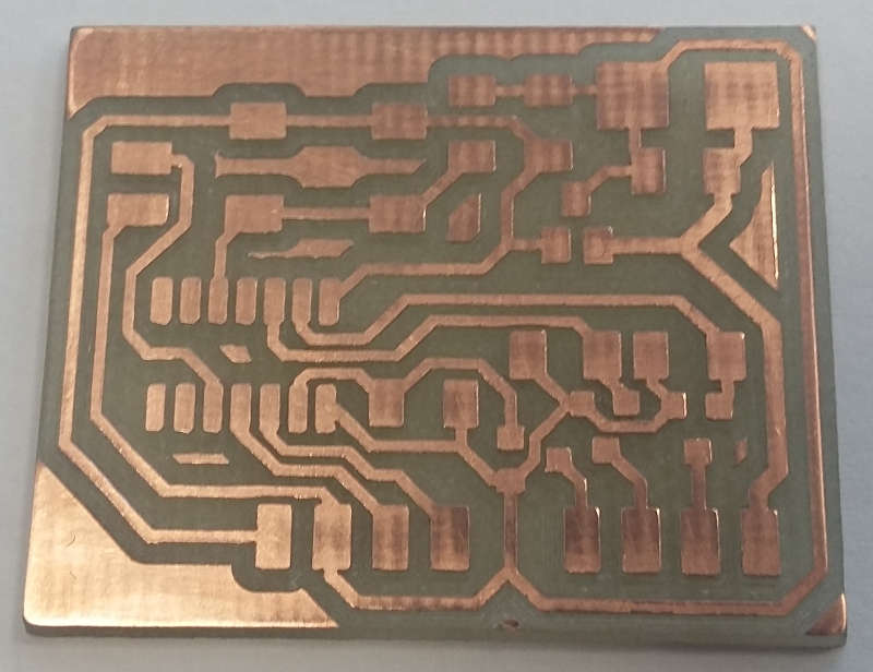
Manufacture
Programming
The coffee table
Mistakes
This week was full of mistakes. For my first board I did the same thing as the electronics design week. I added a +5V to the UPDI to be able to program it only by connecting it to my computer. But it isn’t the same configuration since I also have a 5V regulator. So when I connected my second supply via USB/UPDI, the current was going through the regulator in the wrong way and burned it out. However, it wasn’t instantaneous and took some time, at the beginning it was working perfectly. So when the incident happened I did not understand what was going on.