14. Networking and communications
This week, I am getting deeper on the boards I have created for the inputs and outputs devices. I will try different ways to communicate among them.
ASCII
From Wikipedia:
Abbreviated from American Standard Code for Information Interchange, is a character encoding standard for electronic communication. ASCII codes represent text in computers, telecommunications equipment, and other devices. Most modern character-encoding schemes are based on ASCII, although they support many additional characters.
The Internet Assigned Numbers Authority (IANA) prefers the name US-ASCII for this character encoding.
OSI Layers:
From Wikipedia: OSI layers
The Open Systems Interconnection model (OSI model) is a conceptual model that characterises and standardises the communication functions of a telecommunication or computing system without regard to its underlying internal structure and technology. Its goal is the interoperability of diverse communication systems with standard communication protocols.
| Layer | Protocol data unit (PDU) | applications | Function |
|---|---|---|---|
| 7 | Application | Data | High-level APIs, including resource sharing, remote file access |
| 6 | Presentation | Data | Translation of data between a networking service and an application; including character encoding, data compression and encryption/decryption |
| 5 | Session | Data | Managing communication sessions, i.e., continuous exchange of information in the form of multiple back-and-forth transmissions between two nodes |
| 4 | Transport | Segment, Datagram | Reliable transmission of data segments between points on a network, including segmentation, acknowledgement and multiplexing |
| 3 | Network | Packet | Structuring and managing a multi-node network, including addressing, routing and traffic control |
| 2 | Data link | Frame | Reliable transmission of data frames between two nodes connected by a physical layer |
| 1 | Physical | Bit, Symbol | Transmission and reception of raw bit streams over a physical medium |
What I have learned !
| Layer | Protocol data unit (PDU) | more simple words | Examples |
|---|---|---|---|
| 7 | Application | http / https(No Man in the middle) | SSH(remote control)take control from another computer/ FTP/(uploader/download files) |
| 6 | Presentation | Keys,certificates | security |
| 5 | Session | communication between developper and layer 4 via API (interface) | socket->object->serial.begin() ; serail.print |
| 4 | Transport | TCP (->/<-)Acknowledgement UDP(no acknowledgement)video, real time games | TCP/UDP |
| 3 | Network | source/destination | IP(machine adress)/IPV4/IPV6 |
| 2 | Data link | protocols:ehternet/sources adress/destination adress/ data | MAC adress->network cards: ethernet/wifi/Bluetooth (bt)= different adresses |
| 1 | Physical | Bit, Symbol | Electricity/binary/RJ45 |
For Example ” I have a request: Go to google.
1.RJ45 2.ethernet 3.IP google and my IP 4.TCP(checking the integrity of packet) 5.Interface: OS (linux or WIN) <=> FIREFOX 6.ssl certificate. 7.http
Serial communication
Uart
SUMUP
No master/secondary TX RX PLUG UPDI.
Advantages: Universal, cheap, 3 leads (Transmit: TX/ Reception: Rx, Ground GND, and +5V)
Drawbacks: slow (arduino max frequency: 11500 bauds) Only two devices can be connected each other.
UART architecture:
One start bit (0)= synchronization of the receptor Datas: 8 bits (one byte) One STOP bit (1)
While sleeping, the level is (1)
Testing UART
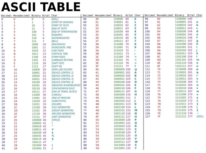
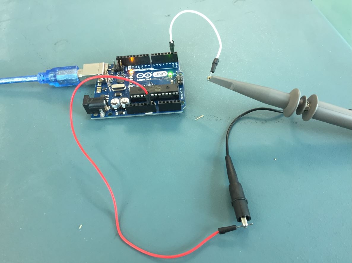
Translating A to ASCII Via the serial.print(A) we send to the OUTPUT board the letter “A ” and observe the “TX” from the Arduino board.
From the Ascii table, we got
|letter|ASCII|hexadecimal(0x)|binaire(0b)| |A||65|”0”1000001|
Nota a “0” is added to the ascii code in order to go from 7 bits to 8 bits.
void setup() {
 Serial.begin(9600);

}
void loop() {
  //Sending the letter "A" code ASCII : 65


  Serial.write(65); // the same as Serial.print("A");

  Serial.write(0);
  }
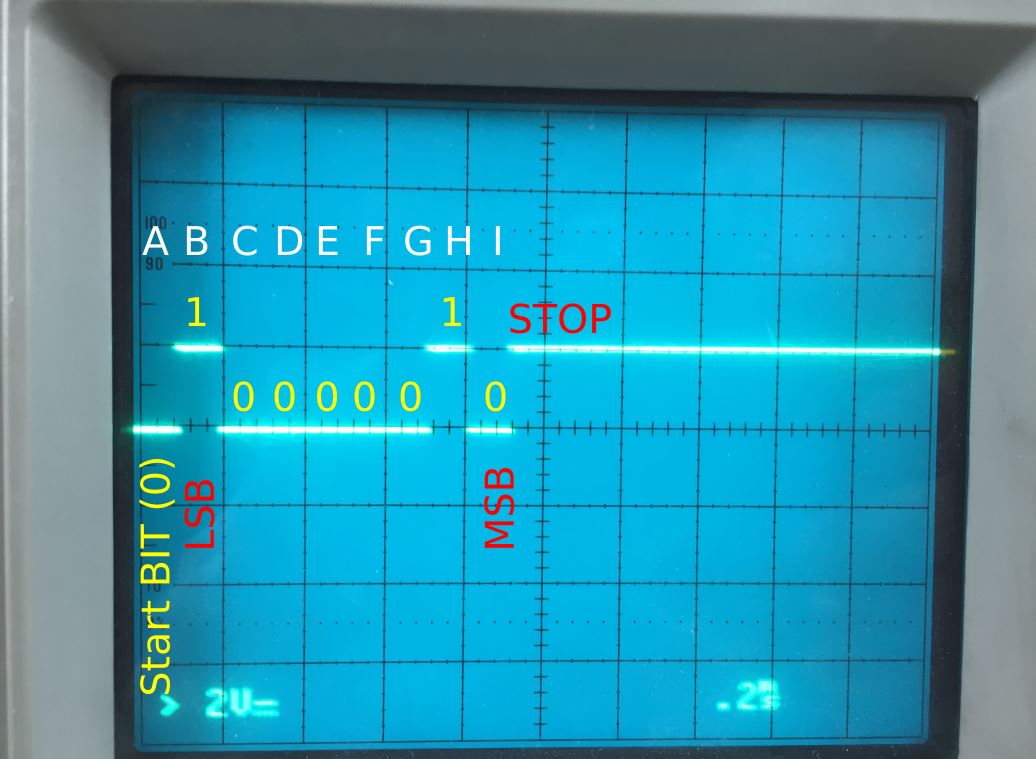
MSB = Most significant bit LSB = Low significant bit
A=Start Bit of the “A” letter, (MSB) 01000001(LSB) For Uart, I need to reverse the code: (LSB)10000010(MSB)
STOP
I2C
master/secondary one communication way.
From wikipedia:
I2C (Inter-Integrated Circuit), pronounced I-squared-C, is a synchronous, multi-master, multi-slave, packet switched, single-ended, serial communication bus invented in 1982 by Philips Semiconductor (now NXP Semiconductors). It is widely used for attaching lower-speed peripheral ICs to processors and microcontrollers in short-distance, intra-board communication. Alternatively, I2C is sometimes spelled I2C (pronounced I-two-C) or IIC (pronounced I-I-C).
From Sparkfun
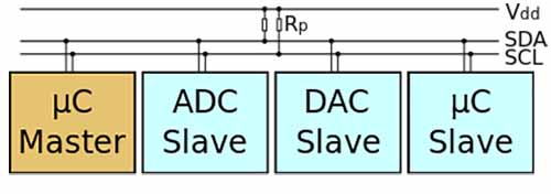
Inter-integrated Circuit (I²C or I2C or IIC) is a protocol designed for connecting multiple integrated circuits and making them communicate with a controller. The controller is called “master” and the other chips are the “slaves”. This bus is intended for short distance communications, and it only requires two wires to exchange information. The protocol was invented in 1982 by Philips, but since October 10, 2006, no licensing fees are required to implement the I²C protocol. Each I2C bus consists of two signals (Fig. 1): SCL and SDA. SCL is the clock signal, and SDA is the data signal. The clock signal is always generated by the current bus master. Messages are broken up into two types of frame: an address frame, where the master indicates the slave to which the message is being sent, and one or more data frames, which are 8-bit data messages passed from master to slave or vice versa. Data is placed on the SDA line after SCL goes low, and is sampled after the SCL line goes high. A well-done tutorial on I2C has been published by Sparkfun.
SPI
master/secondary MISO MOSI from FabISP week05 two communication ways. ISP PLUG
CONNECTING THE INPUT BOARD TO THE OUTPUT BOARD VIA UART.
The goal is to transmit an information from the INPUT Board (IN) to OUTPUT board (OUT) Basicaly, When you switch on the joystick button on (IN), (OUT) will get the information and turn a (OUT) LED on.
First at all, we are going to develop an (IN) program to turn a (IN) LED on.
I use the protocol of output devices week:
And I am programming the Input board to turn on the 6 (IN) LED by switching the button from the joystick. If the button is pressed, then there is an information 1 from Serial.println(1).
To make the communication, we need the serial.begin in the Void setup. The frequency is based on 9600 baud(bit/second). The computer and the microcontroller(MC) have the same frequency. If the computer and the MC receive and transmit datas by using different speed, they will not able to understand each other.
Serial.print is a function to send information. On Arduino, it is a way to get information from serial monitor.
// constants won't change. They're used here to set pin numbers:
const int buttonPin = 0;     // the number of the pushbutton pin
const int ledPin =  6;      // the number of the LED pin

// variables will change:
int buttonState = 0;         // variable for reading the pushbutton status

void setup() {
  // initialize the LED pin as an output:
  pinMode(ledPin, OUTPUT);
  // initialize the pushbutton pin as an input:
  pinMode(buttonPin, INPUT);
  Serial.begin(9600);
}

void loop() {
  // read the state of the pushbutton value:
  buttonState = digitalRead(buttonPin);

  // check if the pushbutton is not pressed. If it is, the buttonState is HIGH:
  if (buttonState == HIGH) {
    // turn LED on:
    digitalWrite(ledPin, LOW);
  Serial.println(0);
  } else {
    // turn LED off:
    digitalWrite(ledPin, HIGH);
      Serial.println(1);
  }
}
Get information from (IN) to turn on a (OUT) LED
We want to receive the information (1) from serial.println (IN) to turn on (OUT)LED. Notice:
TX from (IN) ==> RX from (OUT) RX from (OUT)==> TX from (IN)
Inbyte is the bit coming from (IN)
ready signal is used to know if the led is working.
Serial.available is the function to know if there is a coming message.
Serial.read is the function to read the data from the serial communication.
int inByte = 0;         // incoming serial byte

void setup() {
  // start serial port at 9600 bps and wait for port to open:
  Serial.begin(9600);
  // wait for serial port to connect. Needed for native USB port only


  pinMode(A4, OUTPUT);   // LEd on A4 pin
 digitalWrite(A4,HIGH); // READY signal
}

void loop() {
  // if we get a valid byte, read analog ins:
  if (Serial.available() > 0) {
    // get incoming byte:
    inByte = Serial.read();


    //traiter l'information
    if(inByte == '0' ) {
      digitalWrite(A4,LOW);
    }
    else if(inByte =='1'){
      digitalWrite(A4,HIGH);
    }
I2C communication
From the output device week, I have added an Adafruit 12 servo channels drivers. I used the library
/***************************************************
  This is an example for our Adafruit 16-channel PWM & Servo driver
  Servo test - this will drive 8 servos, one after the other on the
  first 8 pins of the PCA9685

  Pick one up today in the adafruit shop!
  ------> http://www.adafruit.com/products/815

  These drivers use I2C to communicate, 2 pins are required to
  interface.

  Adafruit invests time and resources providing this open source code,
  please support Adafruit and open-source hardware by purchasing
  products from Adafruit!

  Written by Limor Fried/Ladyada for Adafruit Industries.
  BSD license, all text above must be included in any redistribution
 ****************************************************/

#include <Wire.h>
#include <Adafruit_PWMServoDriver.h>

// called this way, it uses the default address 0x40
Adafruit_PWMServoDriver pwm = Adafruit_PWMServoDriver();
// you can also call it with a different address you want
//Adafruit_PWMServoDriver pwm = Adafruit_PWMServoDriver(0x41);
// you can also call it with a different address and I2C interface
//Adafruit_PWMServoDriver pwm = Adafruit_PWMServoDriver(0x40, Wire);

// Depending on your servo make, the pulse width min and max may vary, you
// want these to be as small/large as possible without hitting the hard stop
// for max range. You'll have to tweak them as necessary to match the servos you
// have!
#define SERVOMIN  150 // This is the 'minimum' pulse length count (out of 4096)
#define SERVOMAX  600 // This is the 'maximum' pulse length count (out of 4096)
#define USMIN  600 // This is the rounded 'minimum' microsecond length based on the minimum pulse of 150
#define USMAX  2400 // This is the rounded 'maximum' microsecond length based on the maximum pulse of 600
#define SERVO_FREQ 50 // Analog servos run at ~50 Hz updates

// our servo # counter
uint8_t servonum = 0;

void setup() {
  Serial.begin(9600);
  Serial.println("8 channel Servo test!");

  pwm.begin();
  /*
   * In theory the internal oscillator (clock) is 25MHz but it really isn't
   * that precise. You can 'calibrate' this by tweaking this number until
   * you get the PWM update frequency you're expecting!
   * The int.osc. for the PCA9685 chip is a range between about 23-27MHz and
   * is used for calculating things like writeMicroseconds()
   * Analog servos run at ~50 Hz updates, It is importaint to use an
   * oscilloscope in setting the int.osc frequency for the I2C PCA9685 chip.
   * 1) Attach the oscilloscope to one of the PWM signal pins and ground on
   *    the I2C PCA9685 chip you are setting the value for.
   * 2) Adjust setOscillatorFrequency() until the PWM update frequency is the
   *    expected value (50Hz for most ESCs)
   * Setting the value here is specific to each individual I2C PCA9685 chip and
   * affects the calculations for the PWM update frequency.
   * Failure to correctly set the int.osc value will cause unexpected PWM results
   */
  pwm.setOscillatorFrequency(27000000);
  pwm.setPWMFreq(SERVO_FREQ);  // Analog servos run at ~50 Hz updates

  delay(10);
}

// You can use this function if you'd like to set the pulse length in seconds
// e.g. setServoPulse(0, 0.001) is a ~1 millisecond pulse width. It's not precise!
void setServoPulse(uint8_t n, double pulse) {
  double pulselength;

  pulselength = 1000000;   // 1,000,000 us per second
  pulselength /= SERVO_FREQ;   // Analog servos run at ~60 Hz updates
  Serial.print(pulselength); Serial.println(" us per period");
  pulselength /= 4096;  // 12 bits of resolution
  Serial.print(pulselength); Serial.println(" us per bit");
  pulse *= 1000000;  // convert input seconds to us
  pulse /= pulselength;
  Serial.println(pulse);
  pwm.setPWM(n, 0, pulse);
}

void loop() {
  // Drive each servo one at a time using setPWM()
  Serial.println(servonum);
  for (uint16_t pulselen = SERVOMIN; pulselen < SERVOMAX; pulselen++) {
    pwm.setPWM(servonum, 0, pulselen);
  }

  delay(500);
  for (uint16_t pulselen = SERVOMAX; pulselen > SERVOMIN; pulselen--) {
    pwm.setPWM(servonum, 0, pulselen);
  }

  delay(500);

  // Drive each servo one at a time using writeMicroseconds(), it's not precise due to calculation rounding!
  // The writeMicroseconds() function is used to mimic the Arduino Servo library writeMicroseconds() behavior.
  for (uint16_t microsec = USMIN; microsec < USMAX; microsec++) {
    pwm.writeMicroseconds(servonum, microsec);
  }

  delay(500);
  for (uint16_t microsec = USMAX; microsec > USMIN; microsec--) {
    pwm.writeMicroseconds(servonum, microsec);
  }

  delay(500);

  servonum++;
  if (servonum > 7) servonum = 0; // Testing the first 8 servo channels
}
I have to continue this part.
wireless communication nrf24l01
https://passionelectronique.fr/tutorial-nrf24l01/ https://howtomechatronics.com/tutorials/arduino/arduino-wireless-communication-nrf24l01-tutorial/