3. Computer Aided design
This week I worked on defining my final project idea and started to getting used to the documentation process.
Challenge yourself on Blender
From the decade 2000-2010, I was curious to explore the 3d world and make animations. I have tried 3Dsmax and the documentation online was not good enough. I thought about Blender but the interface was not very user friendly, and I gave up the part of the fabulous freeform 3D. I have learned a lot of 3d parametric softwares such as Autodesk Inventor, Dassault Solidworks, fusion 360°, onshape.
But For the Fabacademy I decided to go deep on Blender, because it seems the design team should have some Interface and ergonomic designers.
First FACE
I have followed some tutorial and will explain how to make a face. https://www.youtube.com/watch?v=9ldg_JPm2rA&t=15s&ab_channel=CBConcept
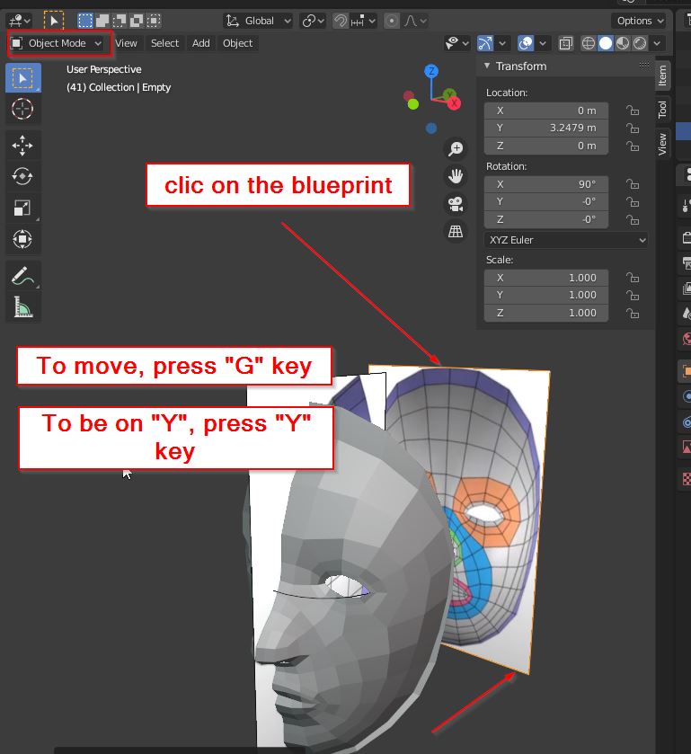
Starting from the wired face blueprints, I gently copy the mesh to make the 3D face. D D
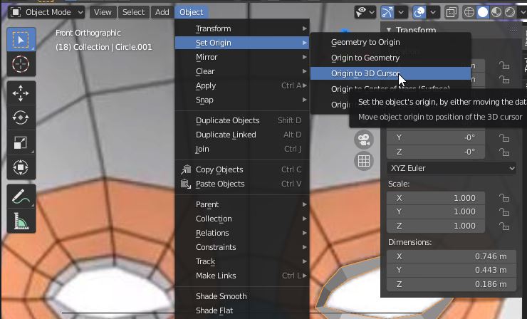
object mode/
object/set origin/ origin to 3d cursor
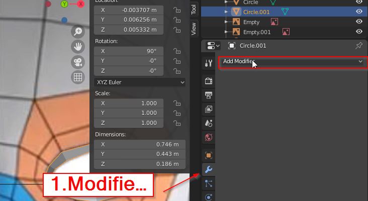
Add modifier: mirror
select mirror
option: clipping the points will not go over the Y-axe.
ADD control points
select object/ edit mode
A select all
Alt+A deselect all
select a line:
Extrude. Right clic
“S” to extrude front the line shape.
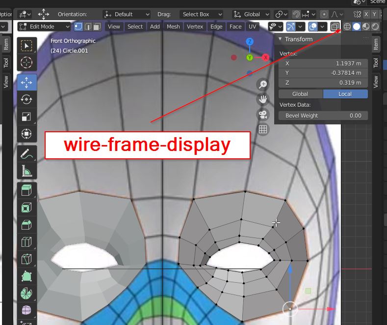
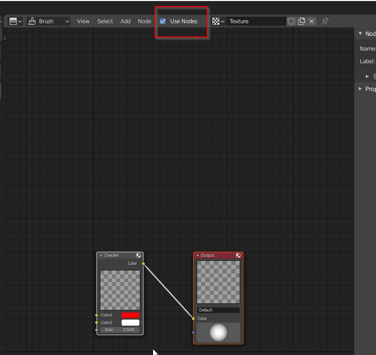
To show the frame, clic on
shortcut Z : wireframe/solid
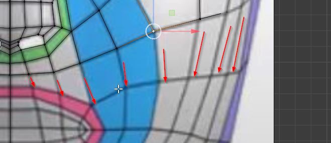
extrude the 3 points to the center line. F face
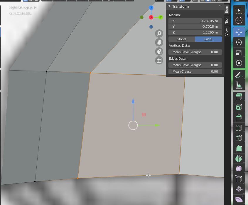
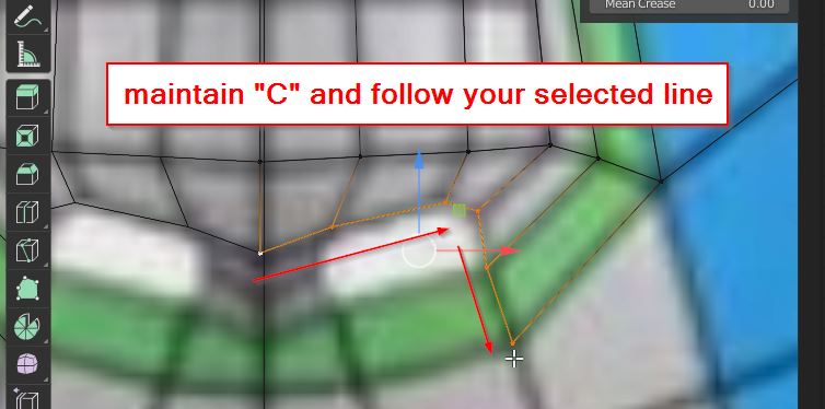
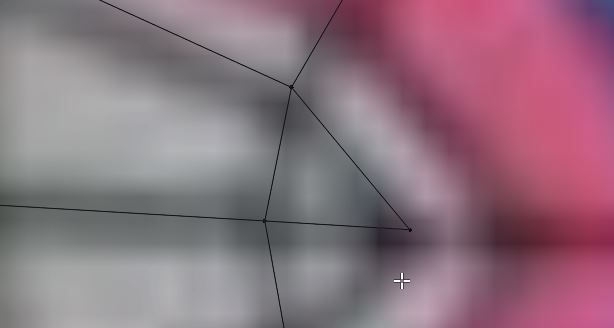
To select an entire line. Clic on one point, next clic “c”,press “c” and follow your desired line.
Img selected-line
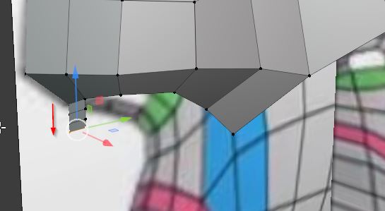
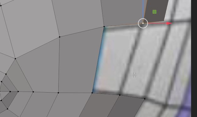
extrude 3 times the edge of the nose.
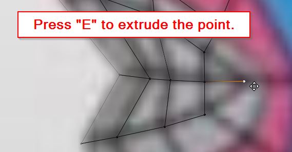
Exrtude a point to get a triangular polygon.
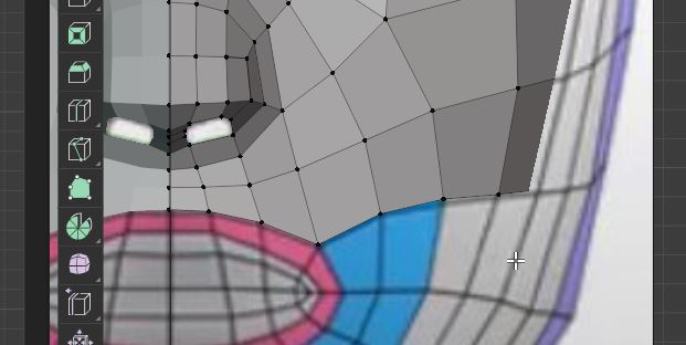
The blueprint has be removed to the back of the face.
Object mode/
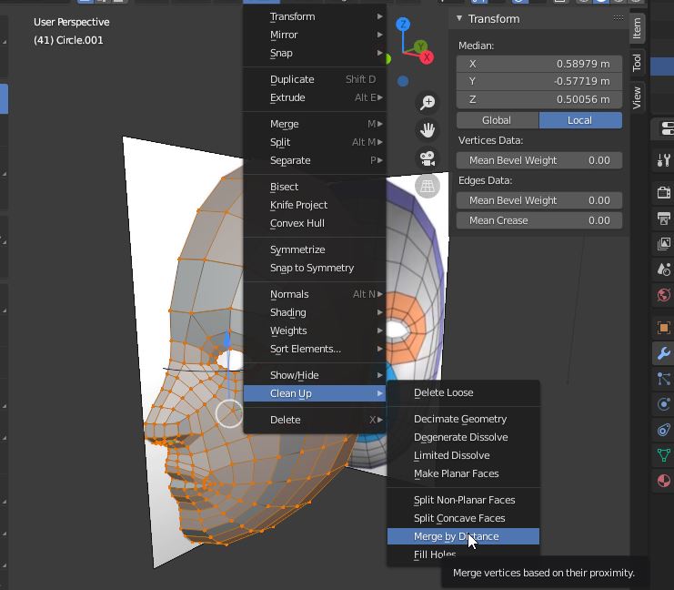
If there is doublon.
mesh/clean up/merge by distance.
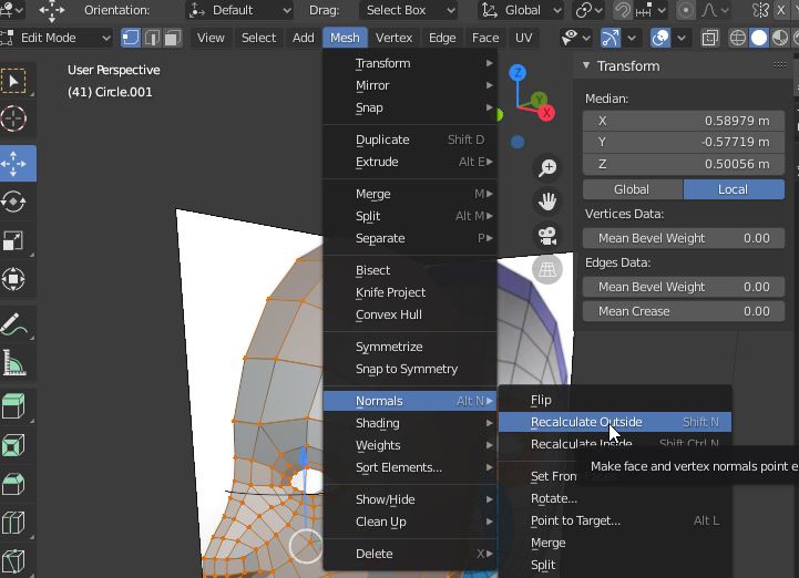
If you have differents polygone faces, there may be have normal faces in opposite directions:
mesh/normals/recalculate outside.
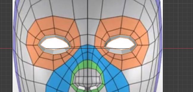
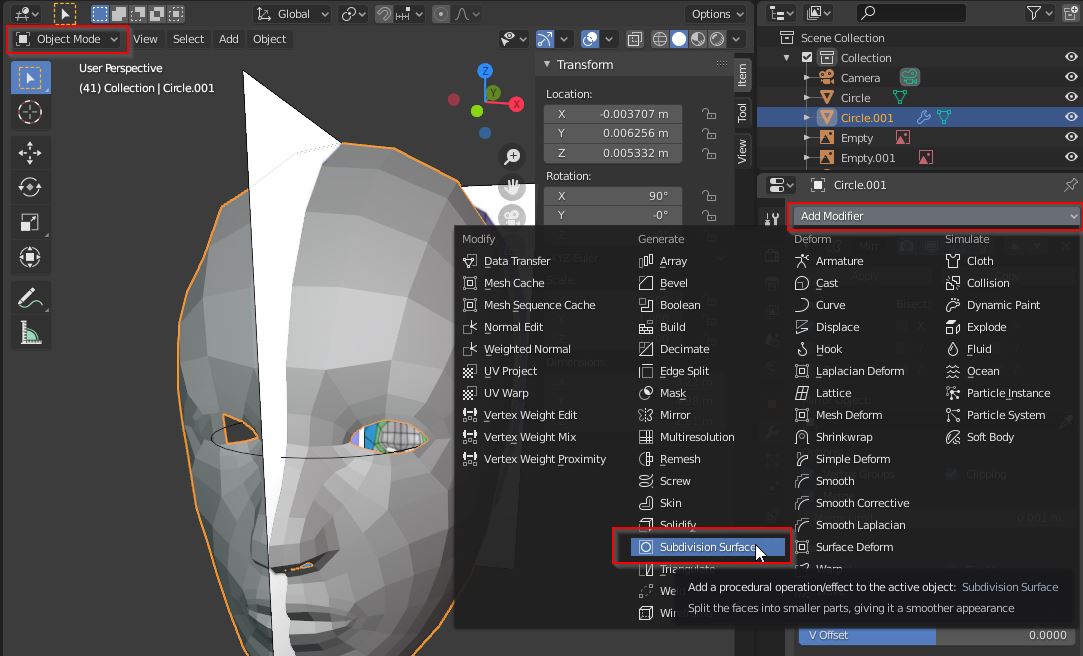
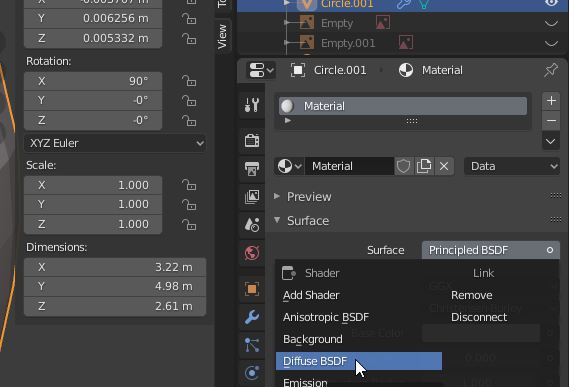
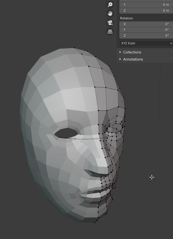
Subdivision de surfaces: add faces adoucit
3 is ok View and render.
RMB shade smooth.
Tab to enter in edit mode.
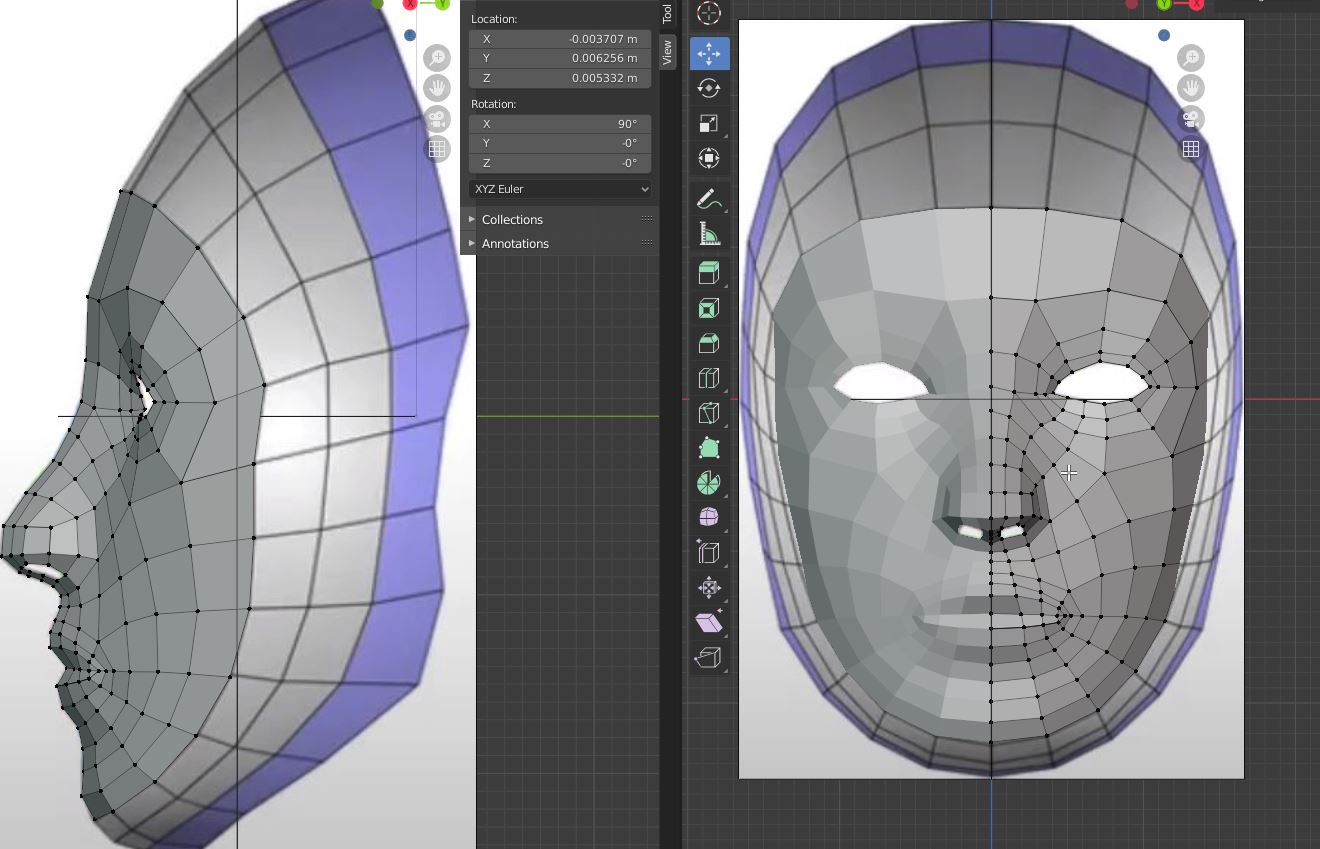
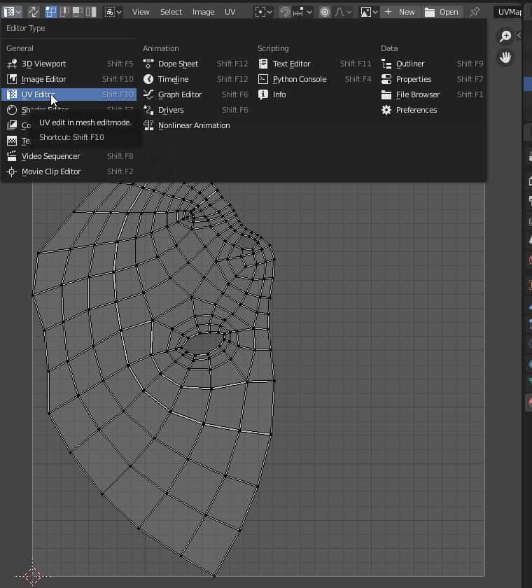
Import the blueprint in the front and the right.
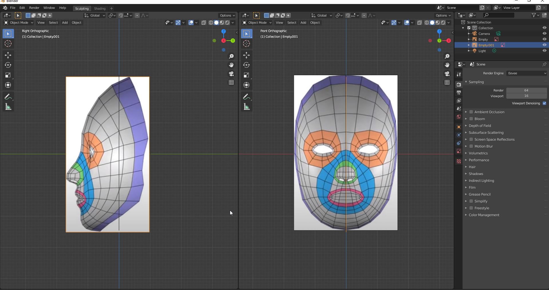
Press N to get the direction tab.
Translate the canvas into 0,0 for the both blueprints.
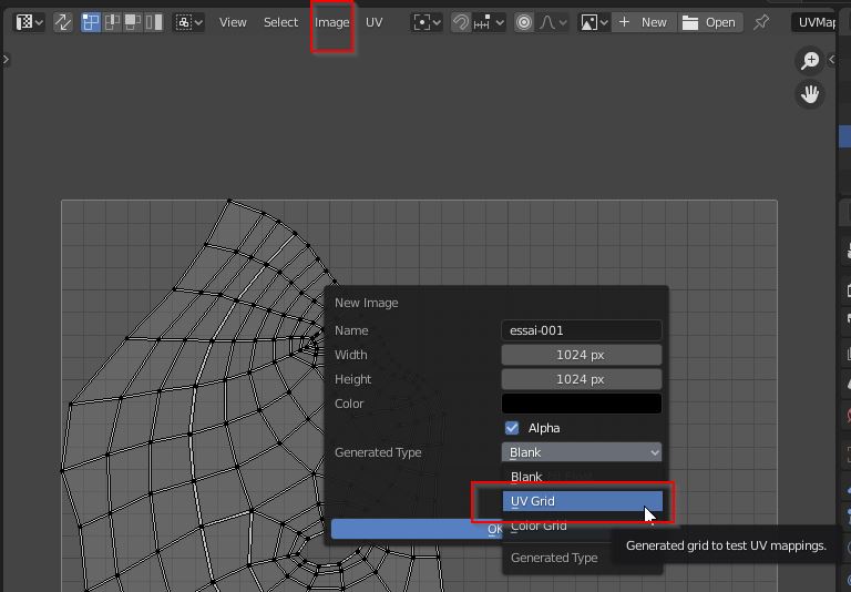
![]()
You get them perfectly matched.
Press key button “3” to be on the right view.
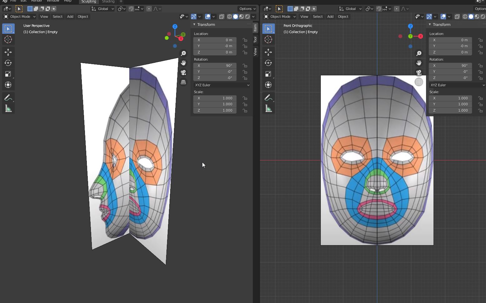
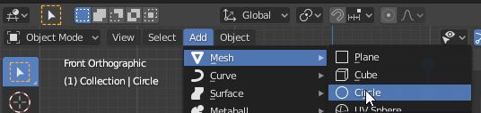
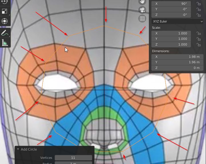
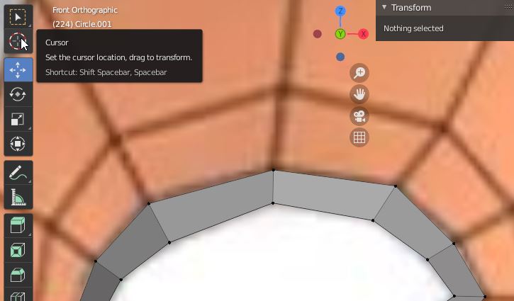
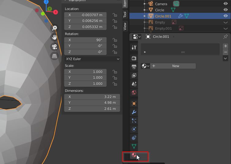
Add a mesh circle.
To have a good resolution, we have 11 control points. Next, you align to the current view.
The circle appears in yellow.
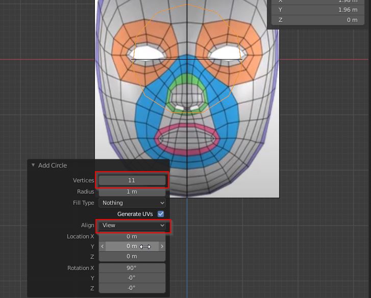 Details of circle.
Press key button “1” to go back on the front view.
 Circle
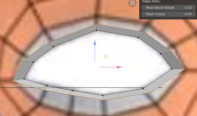
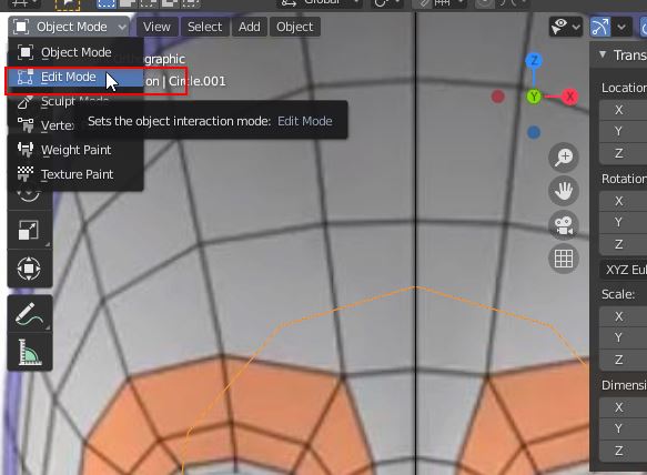 Change from “Object mode” to “edit mode” to modify the mesh circle.
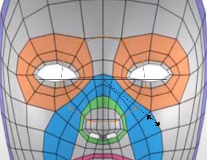
Shortcut: “S” equals “resize”
alt + LBM = 90° rotation. MAJ + LBM = dragging ctrl + lbm = zooming
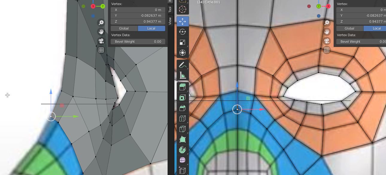
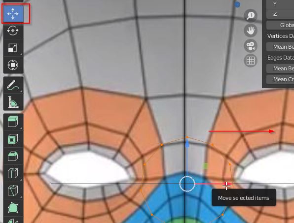 Moving the circle to the eye.
 control point
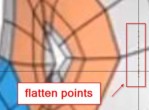
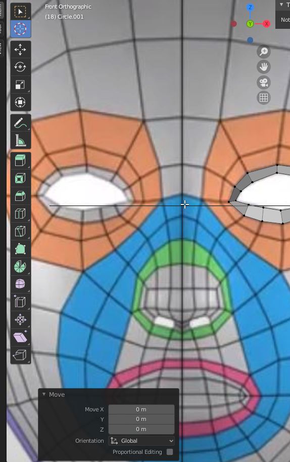
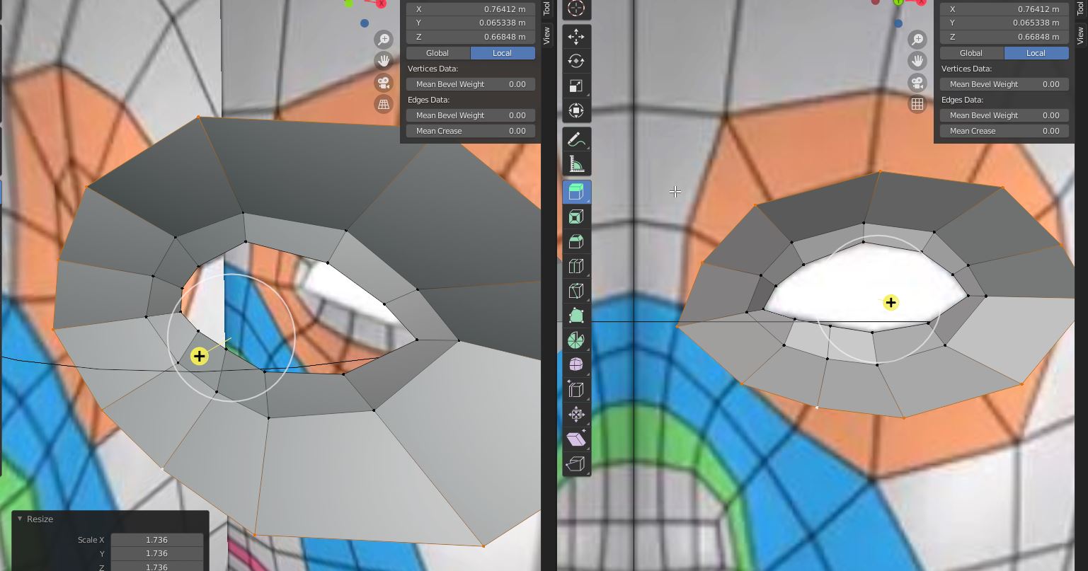
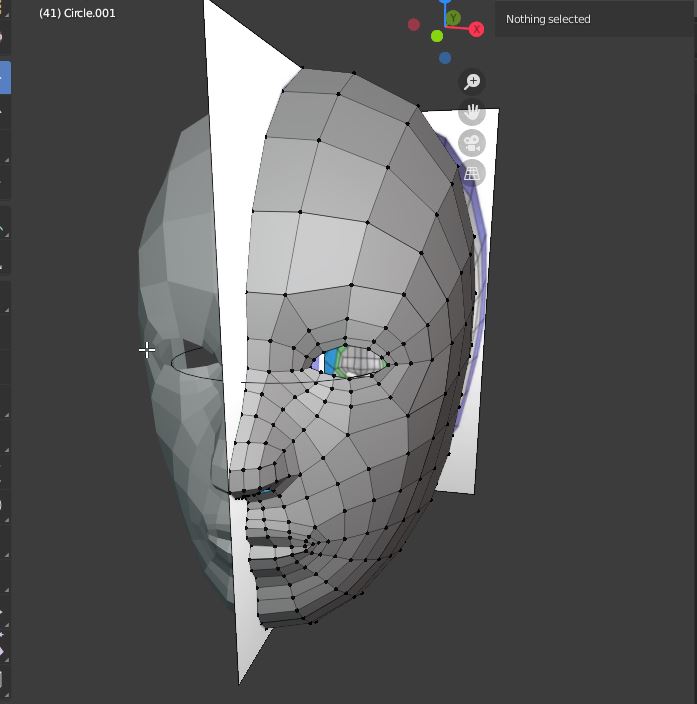
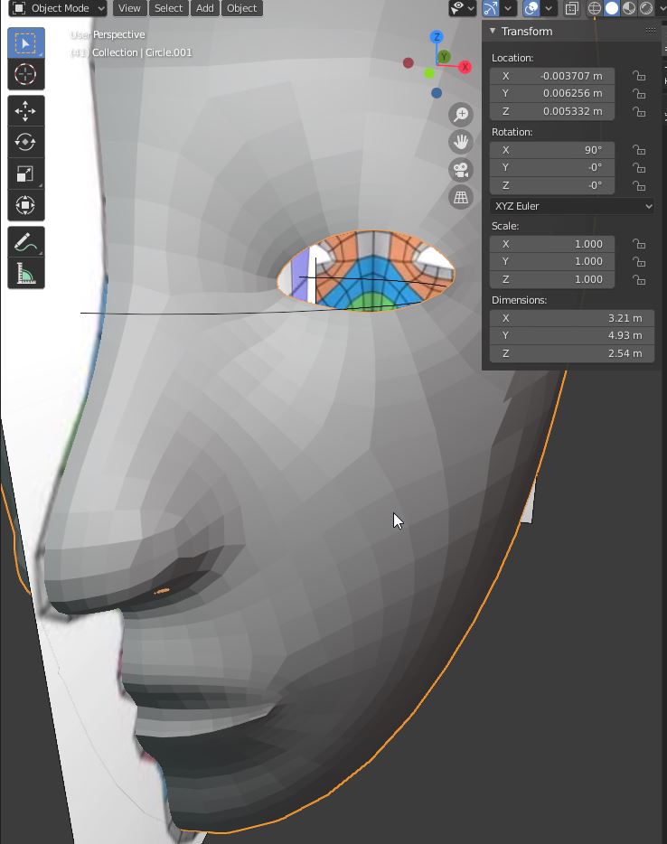
On the right view, you can see the flatten points.
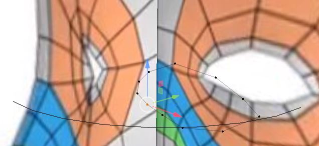
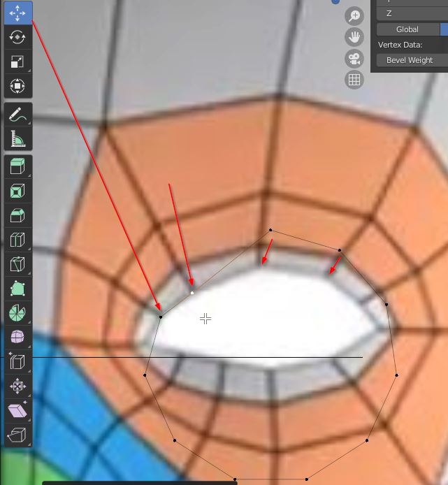
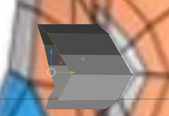
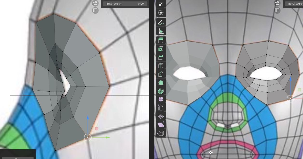
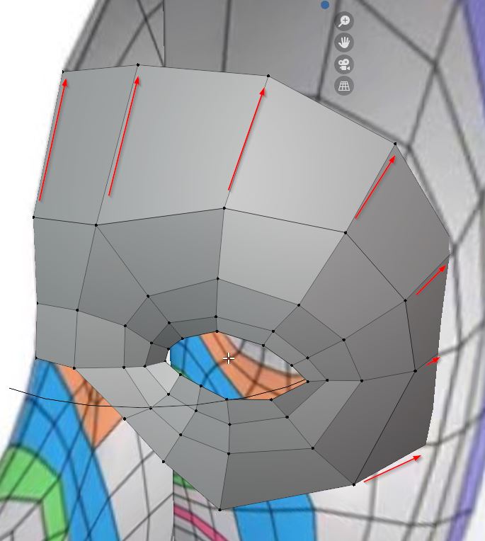
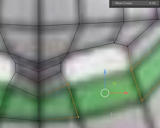
extrude the circle points
resize (S) A – select all control points. E- extrude right clic for options : extrude according to the selected points.
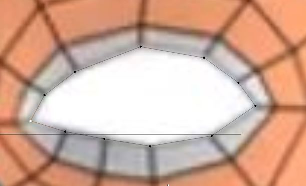
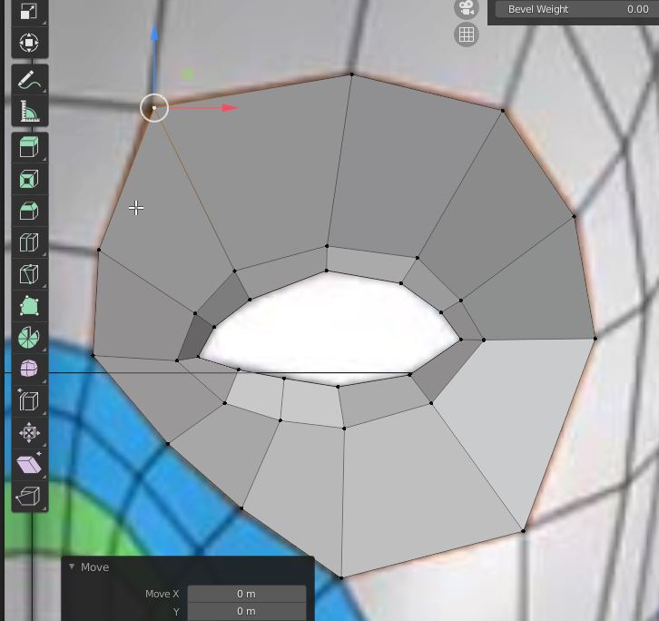
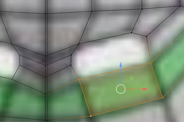
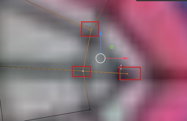
-relocate the points according to the two views.
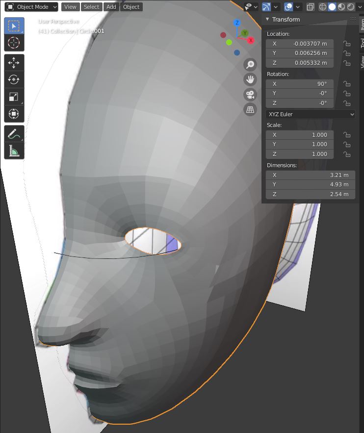
you got the second line of the eyelid
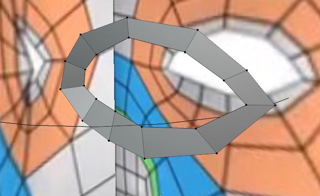
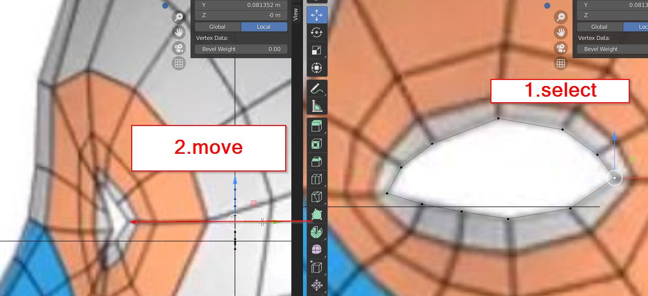
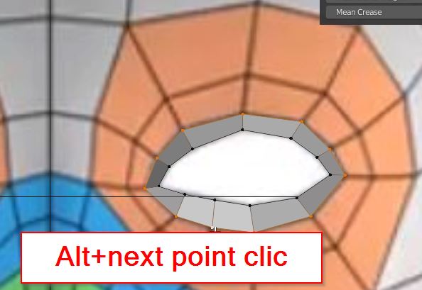
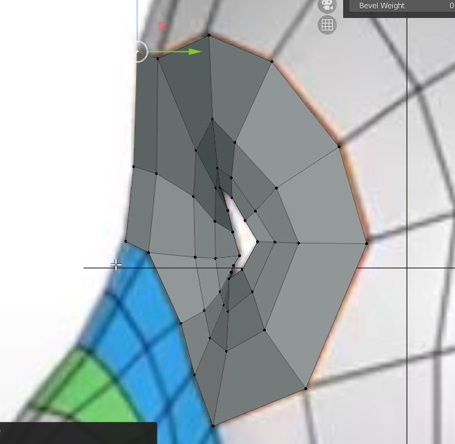
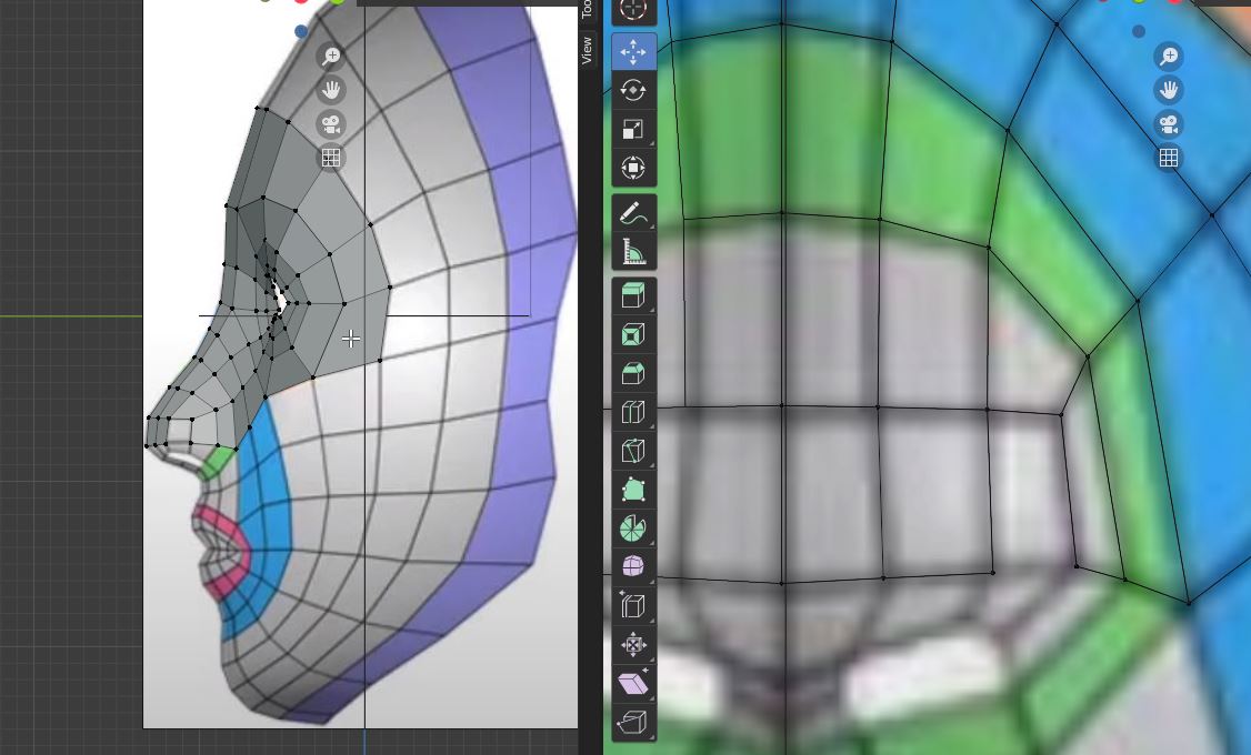
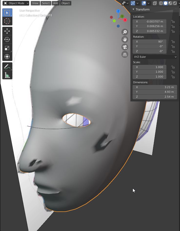
Move the points according to your blueprints
miror

Second Face on BLENDER !!!
Useful links
Code Example
Use the three backticks to separate code.
// the setup function runs once when you press reset or power the board
void setup() {
  // initialize digital pin LED_BUILTIN as an output.
  pinMode(LED_BUILTIN, OUTPUT);
}

// the loop function runs over and over again forever
void loop() {
  digitalWrite(LED_BUILTIN, HIGH);   // turn the LED on (HIGH is the voltage level)
  delay(1000);                       // wait for a second
  digitalWrite(LED_BUILTIN, LOW);    // turn the LED off by making the voltage LOW
  delay(1000);                       // wait for a second
}
Gallery

Video
From Vimeo
Sound Waves from George Gally (Radarboy) on Vimeo.