9. Embedded programming
This week I have to read a microcontroller data sheet(ATtiny44) and program the board from week 07 to do something.
Arduino Board
Arduino boards provides inputs and outputs such as:
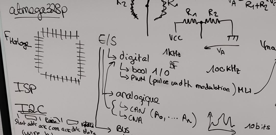
digital outputs:
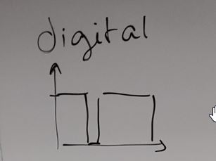
bool 1/0 PWM also called MLI in frenche.
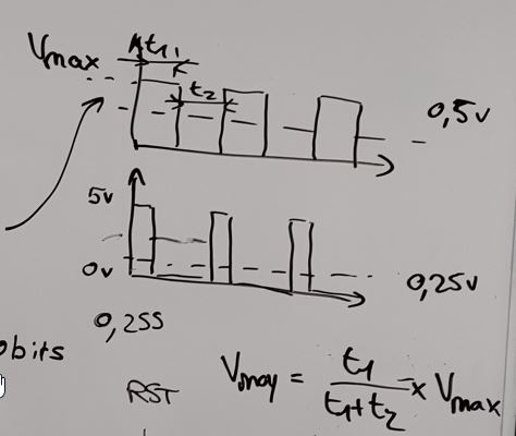
According to the time, we can calculate the medium voltage.
analog outputs:
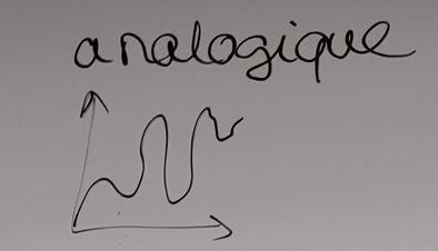
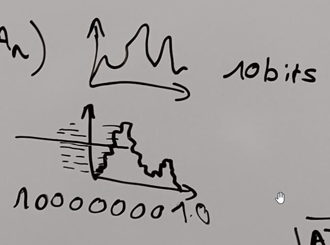
This is typical as the potentiometer, we have a irregular signal. CAN (A0,A1,A2) CNA Reading microcontroller datasheets, you can easily find out the can pins called ADC equals Analog- Digital - converter, which means the pin to plug a potentiometer.
To get in the “MCU”, the analog signal is converted to digital signal as an incremental signal.
It works on the clock (Frequency) to send datas. As a maestro, the rythm of the music has to be on time for each instrument to synchronize.
There are couple of ways to communicate via buses:
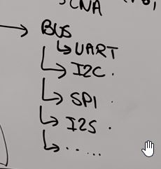
UART
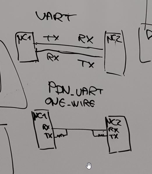
TX RX, serial communication, very easy.
I2S, Sound interface communication.
I2C
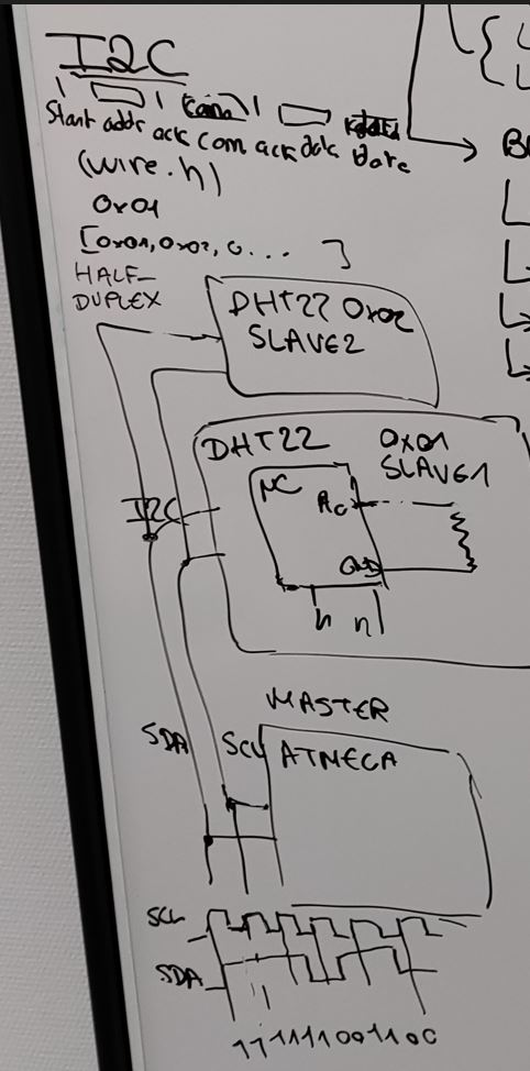
HALF DUPLEX
The communication is unilateral. ack j’ai bienreçu l’adress. Commande. Ack données. Trame est porteuse de l’adresse. Bibliothuqèe wire.h.
communique 0x01 et ecvoie les paquetes de données ;
SPI
bilateral communication.
USI : universal serial Interface.
Master / slave
The communication is bilateral.
Il peuvent commniquer. En meme temps.
Cs selection
usi deux de gdonnées
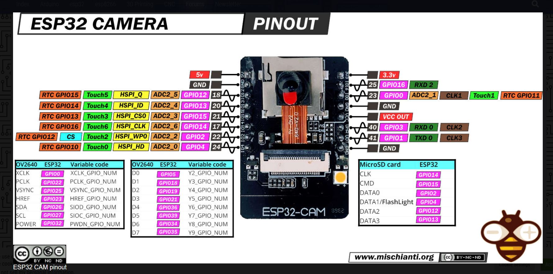
ESP 32 - discovering
ESP-32 works on 3.3 V.
Pinouts
Programming.
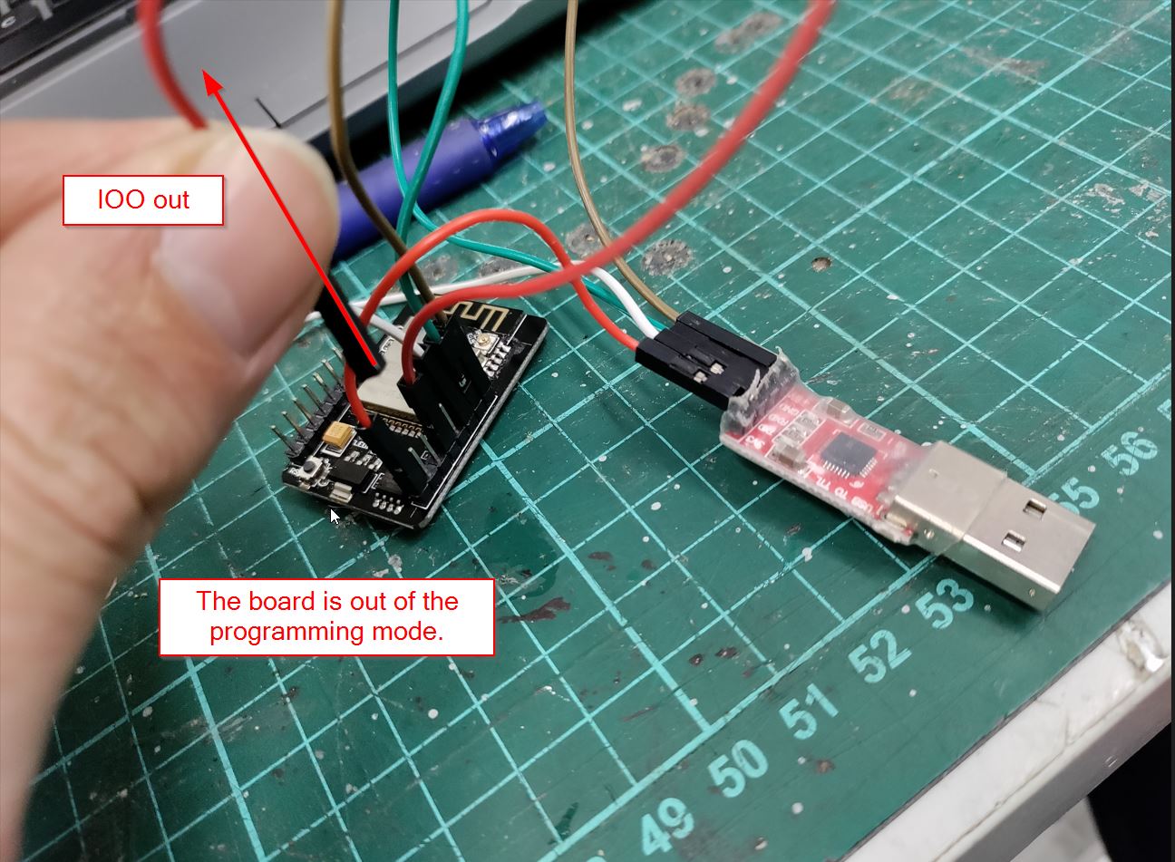
2 Pins need to be linked, IOO and GND.
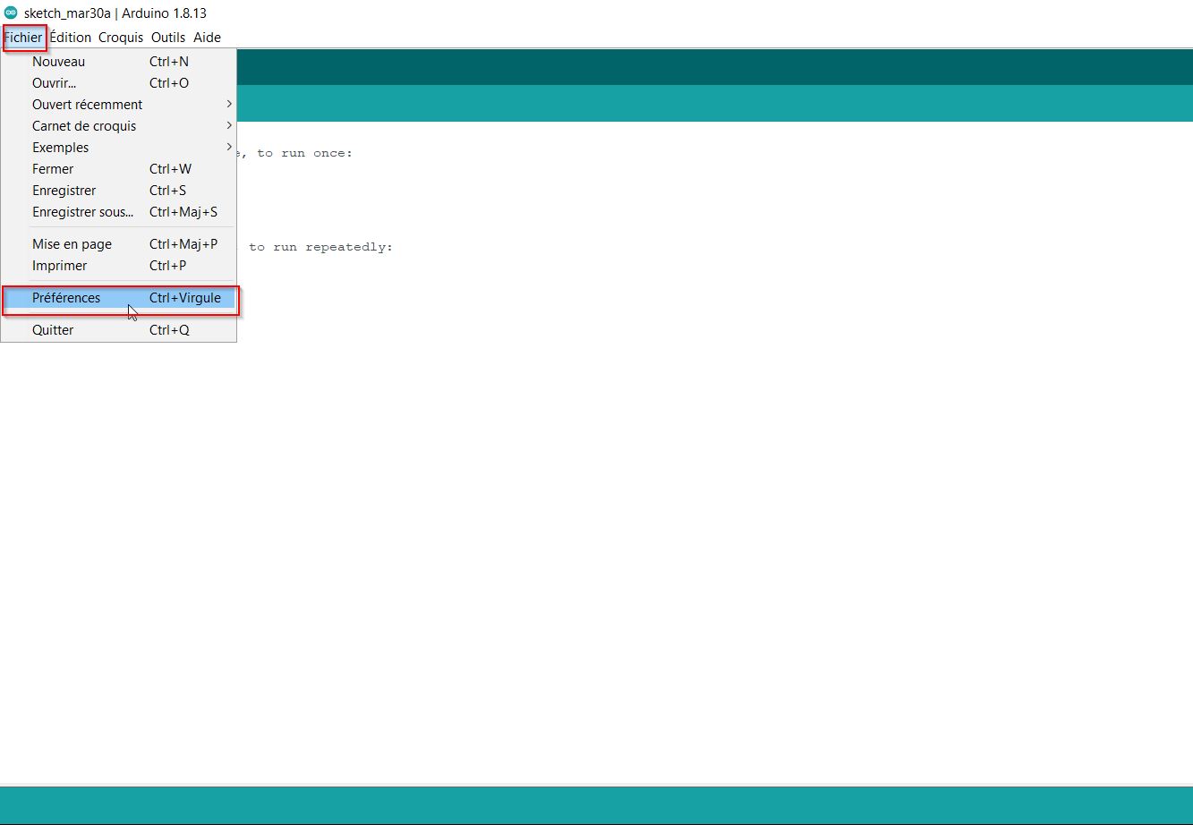
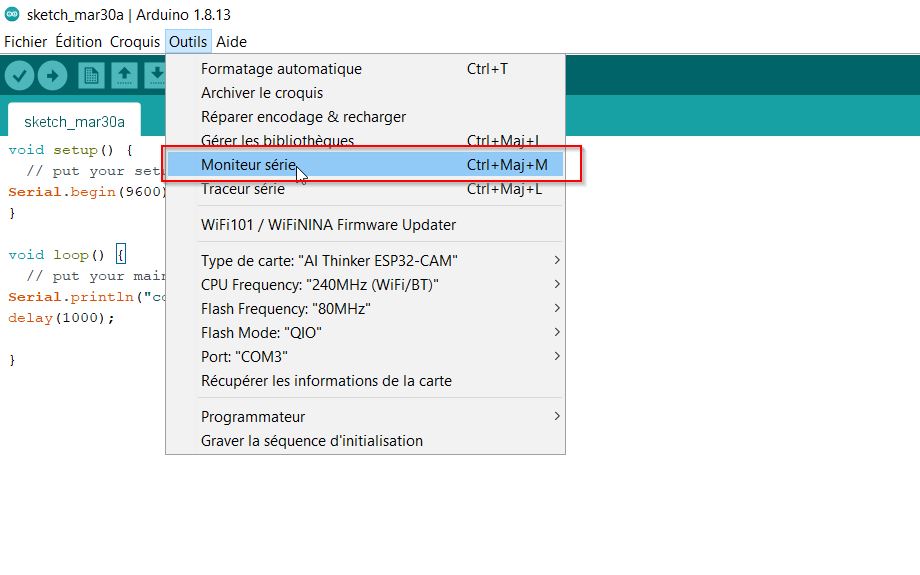
Arduino.
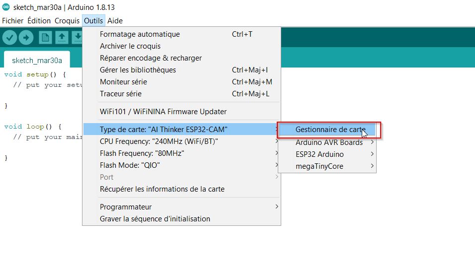
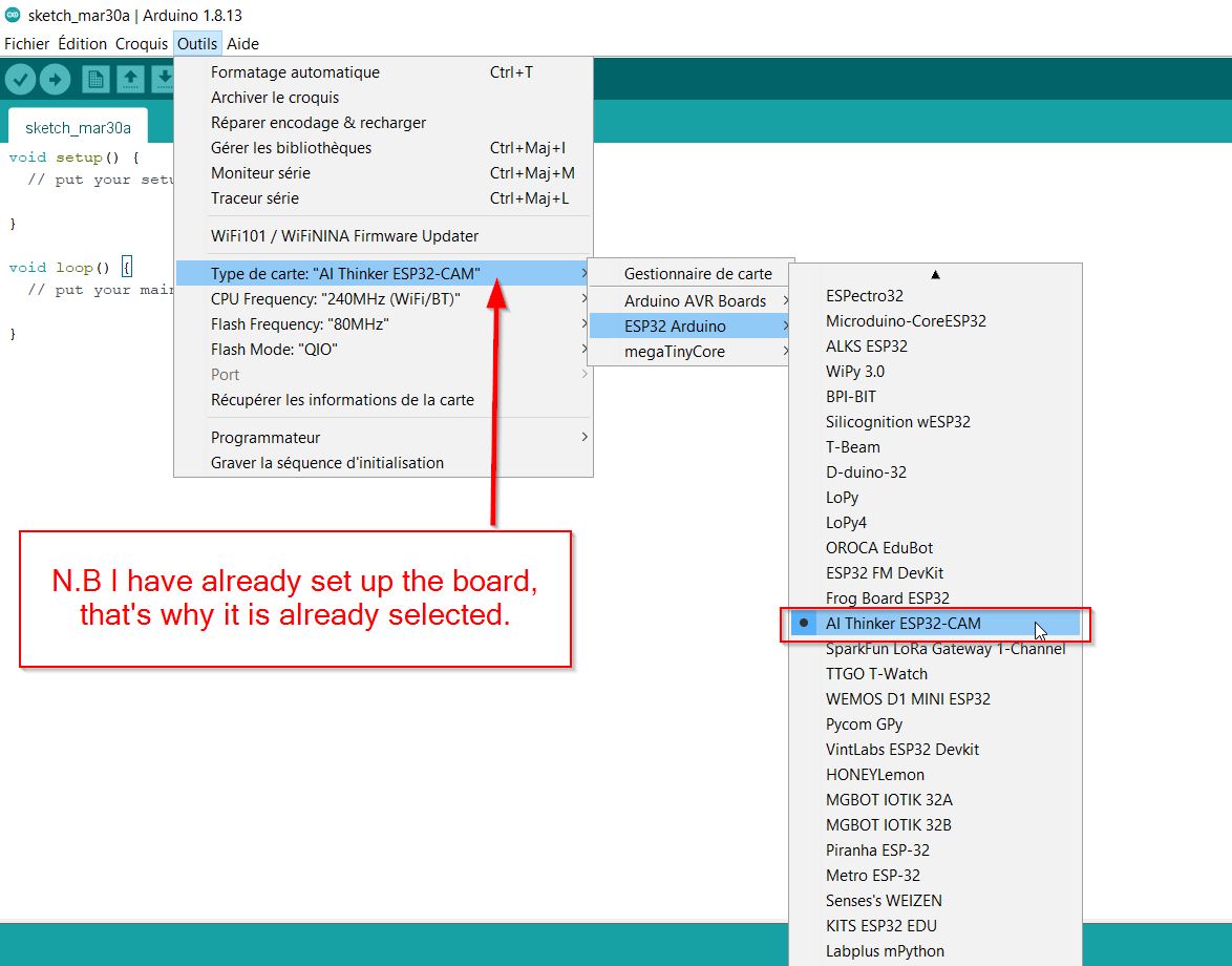
First thing is to add the ep 32- cam
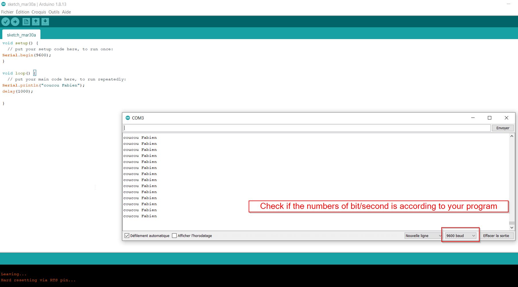
9600 bits/sec
to add Microcontroller libraries, just add “; ” https://dl.espressif.com/dl/package_esp32_index.json;
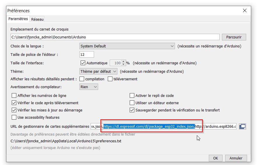
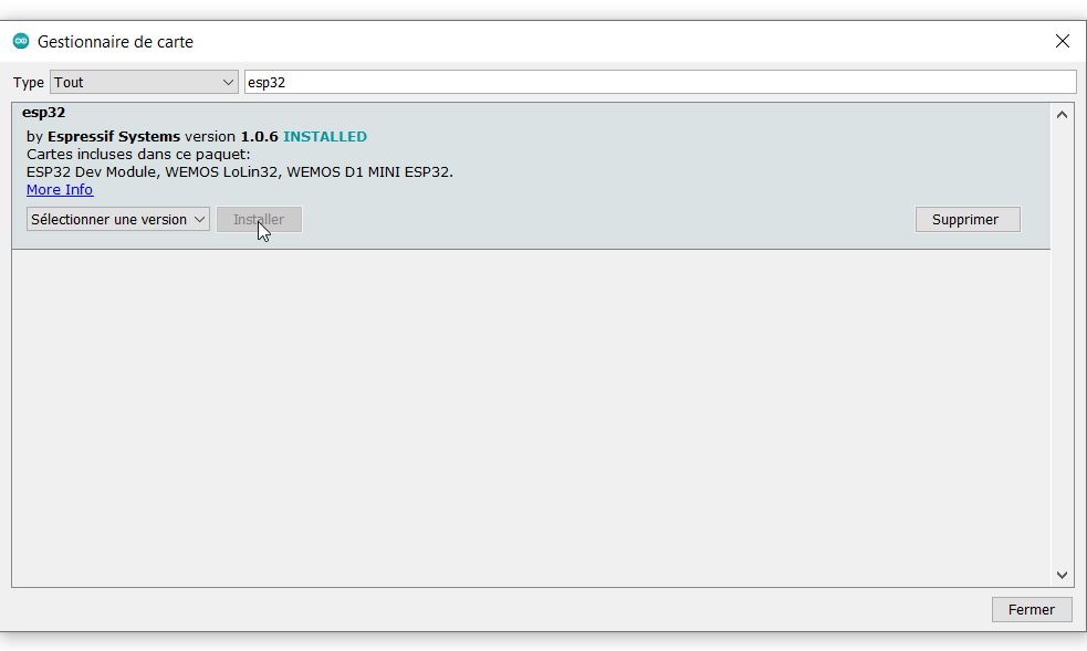
Install the esp 32
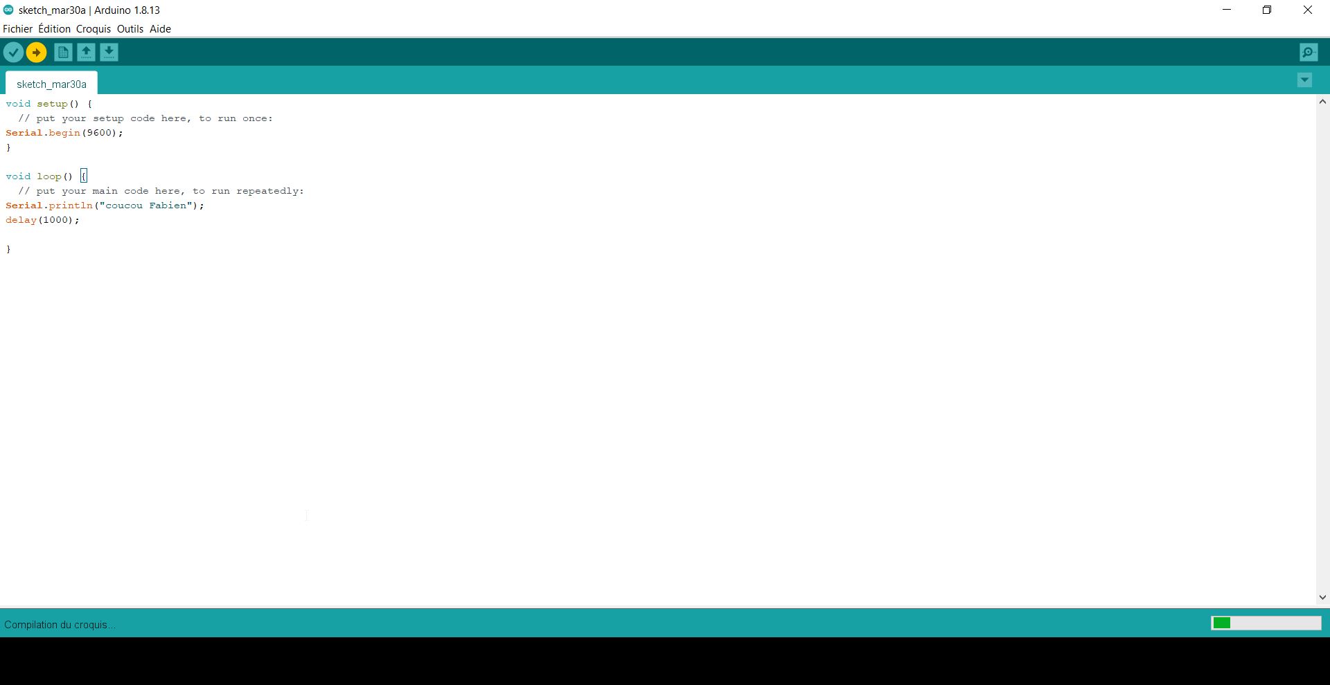
Here comes my simple code:
void setup() {
  // put your setup code here, to run once:
Serial.begin(9600);
}

void loop() {
  // put your main code here, to run repeatedly:
Serial.println("coucou Fabien");
delay(1000);

}
Next, you check and compile the code:
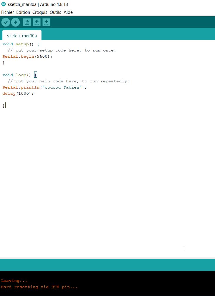
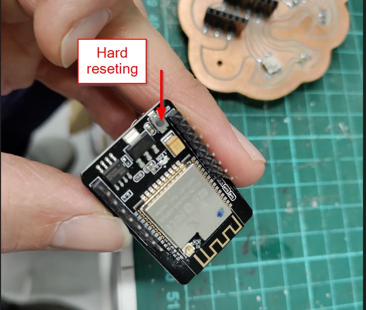
Normaly you should do the hard reseting by pressing the button behind the esp-32 board. But it is not convenient.
Another way is to unplug the usb - ttl - converter. You remove the IOO-GND link, and plug the board via usb again.
Hard reseting. Normaly you should use the reset button
The esp-32 cam is working so it is time to install it on my board.
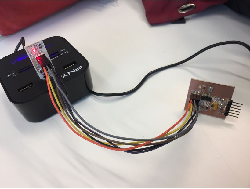
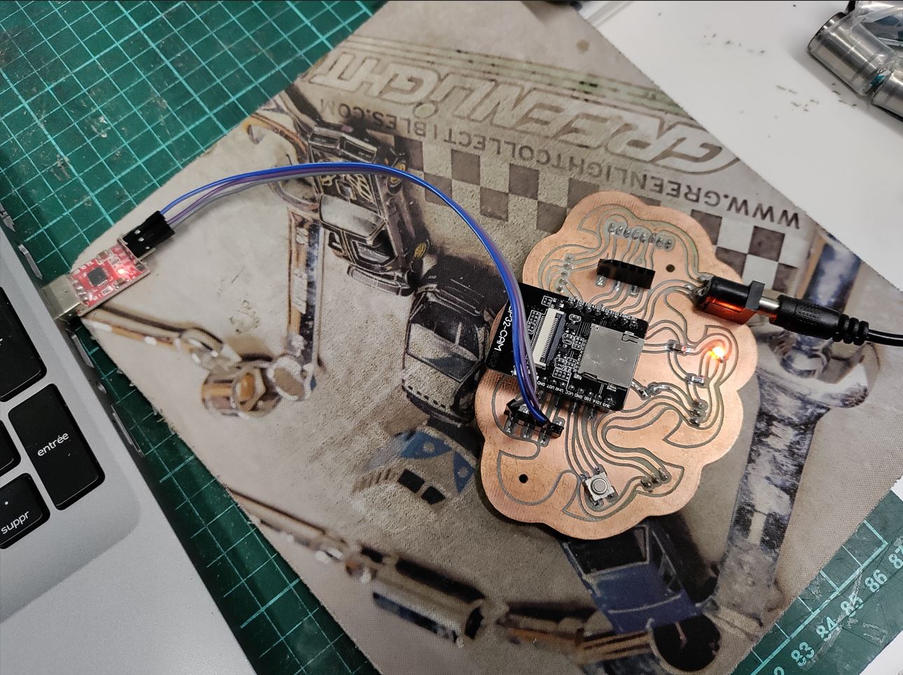 The procedure is the same but I got a first problem. For programming, I did not put the GND on the ttl programmer. I was not able to load my program.
communicating .....communicating.....communicating.....
Albin one of my colleague, gave me some trick.
Checking the continuity and there is 3.3V on the multimeter.
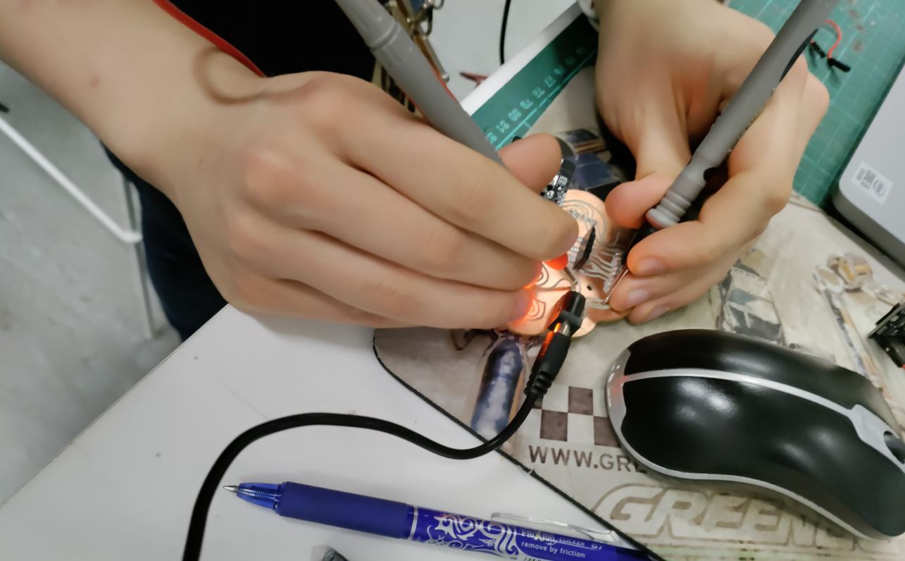
Continuity switch Checking 3.3V Voltage and GND.
Having a look, he told me that I forgot the gnd on the programmer. I thought the 5V -1A brought from the board was enough, but my friend told me that there is no reference coming from the ttl converter. I linked the wire, and was able to load my test program.
The second problem was the DC plug, the inner diameter is 1.5 for the plug and the DC adapter is 2.5mm.
Data sheet:
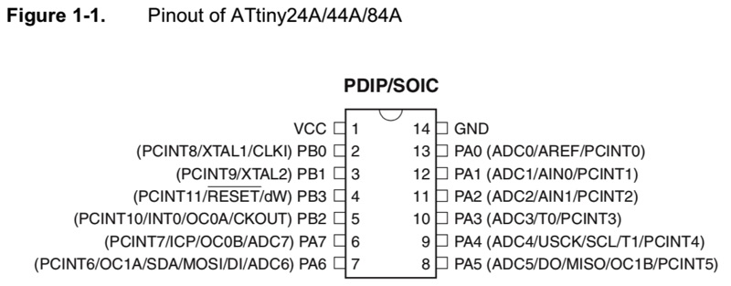
To familiarize myself with the technical data of microcontroller and especially to know the specifics of each pin, I read the ATtiny44 A datasheet. I also had to look for the correspondence between the different pins according to the languages and programming tools used. Especially to make the serial communication work.
| cellule 1 | cellule 2 |
|---|---|
| A | B |
| C | D |
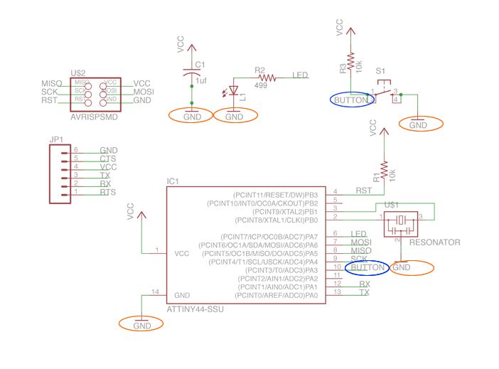
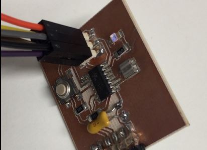
Here comes my schematics from my ATtiny44 board:
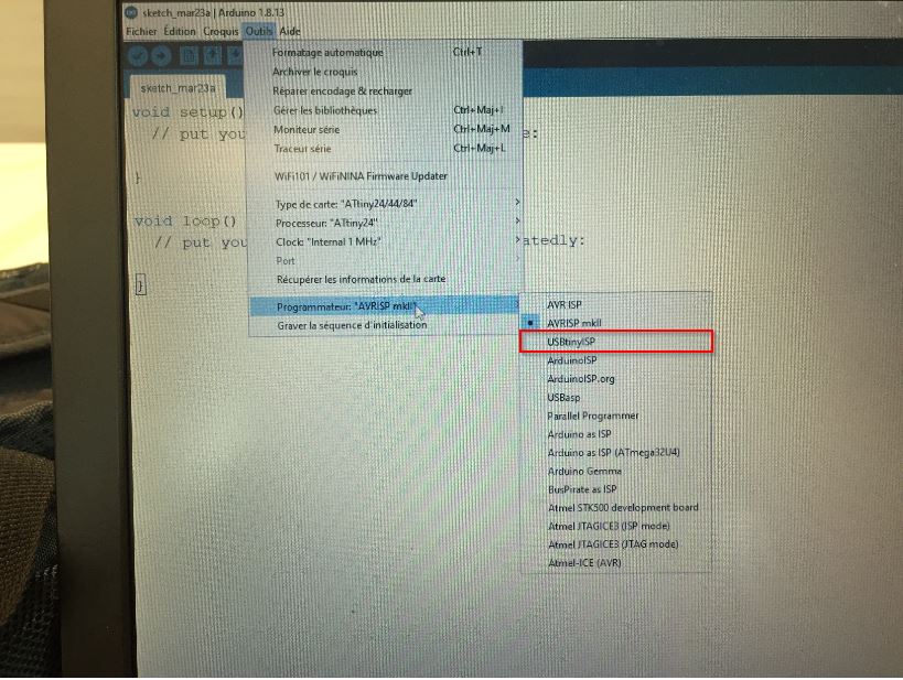
ARDUINO IDE.
I need an in-system programmer (ISP) created during the week05: THE FABISP
 To be at work, I download the usbtiny driver from adafruit.
The programmer fabisp has been selected:
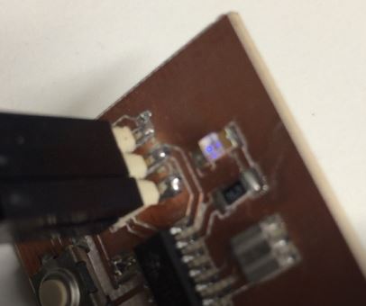
I had some FAILS because I did not find the proper pinnouts. Firstly, I changed the pinnout from blinking to pin6. But pin6 is called PA7 and Button is on pin 10 which means : PA3
When the board was flashed, I did not see anything. In fact, my blue LED is not shiny.WRONG CHOICE. Anyway I thought the board had a problem but not. Great
Blinking
// the setup function runs once when you press reset or power the board
void setup() {
  // initialize digital pin LED_BUILTIN as an output.
  pinMode(LED_BUILTIN, OUTPUT);
}

// the loop function runs over and over again forever
void loop() {
  digitalWrite(PA7, HIGH);   // turn the LED on (HIGH is the voltage level)
  delay(1000);                       // wait for a second
  digitalWrite(PA7, LOW);    // turn the LED off by making the voltage LOW
  delay(1000);                       // wait for a second
}
Switch button
// constants won't change. They're used here to set pin numbers:
const int buttonPin = PA3;     // the number of the pushbutton pin
const int ledPin =  PA7;      // the number of the LED pin

// variables will change:
int buttonState = 0;         // variable for reading the pushbutton status

void setup() {
  // initialize the LED pin as an output:
  pinMode(ledPin, OUTPUT);
  // initialize the pushbutton pin as an input:
  pinMode(buttonPin, INPUT);
}

void loop() {
  // read the state of the pushbutton value:
  buttonState = digitalRead(buttonPin);

  // check if the pushbutton is pressed. If it is, the buttonState is HIGH:
  if (buttonState == HIGH) {
    // turn LED on:
    digitalWrite(ledPin, HIGH);
  } else {
    // turn LED off:
    digitalWrite(ledPin, LOW);
  }
}
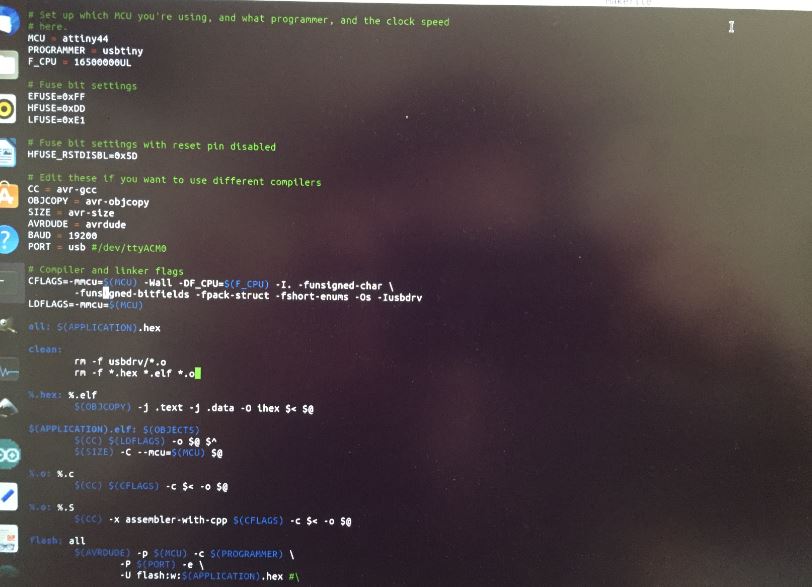
Program using anything else.
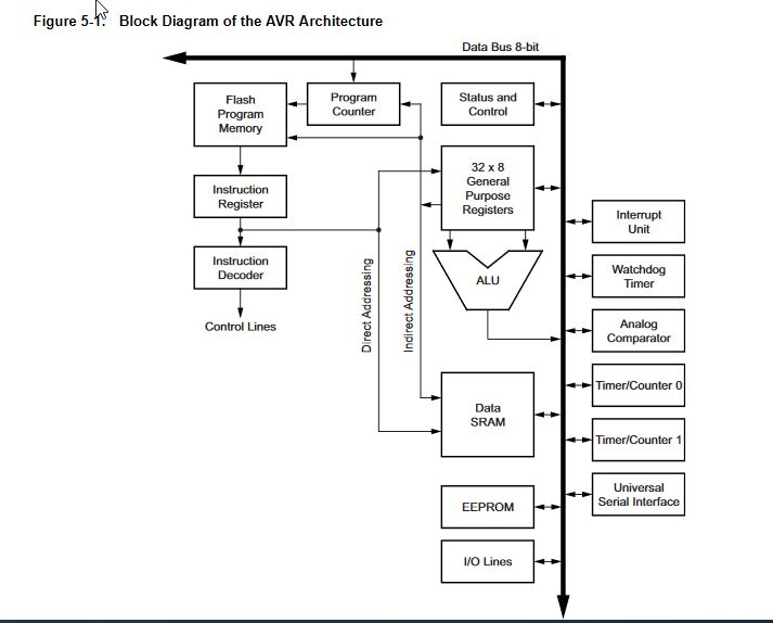
Alex, a electronics teacher and students Arthur, Johnny and Axel explained me the inside of the microprocessor.
I have recently got a linux pc, but I need to move all my datas to this computer. Anyway.
They explain me the tool chain,avrdude MAKE and all the buddies: flash , etc… main.c o etc… It is still a little bit complex for me but I am learning and try to keep that way.