BACK TO HOME PAGE
WEEK 5
3D SCANNING AND PRINTING
WEEK ASSIGNMENTS:
WEEK 5
3D SCANNING AND PRINTING
WEEK ASSIGNMENTS:
Tasks for a week
Task:Group assignment:
At the start, I have learned that how to test 3d printer? then I have tested my fab lab printer and describe Some steps related to the calibrations are given below.
3D PRINTER CALIBRATION STEPS:
1)It is an excellent result of wrap bending.
2)bridge print size is 1.29 mm.
3)The overhang is 50C.
4)Spike result is better.
5)Rounded High Resolution.
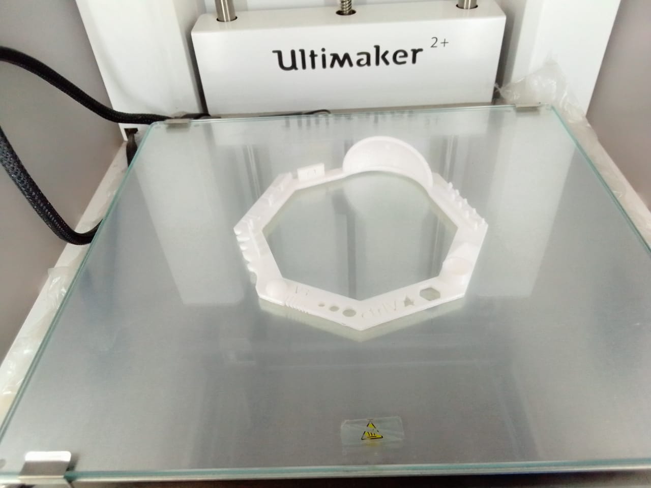
I have given a file of the v3 test card that is download from the fab schedule.

V3 test card.
Task:01 3D-Printing:
What is 3D printing?
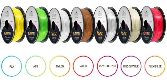
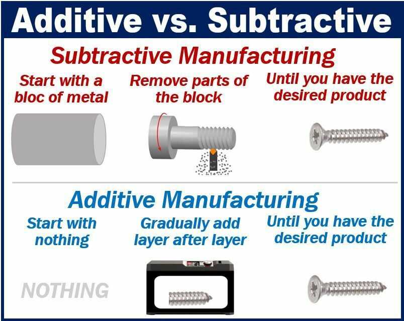
3D printing, also called additive manufacturing, is a family of processes that produces objects by adding material in layers that correspond to successive cross-sections of a 3D model. we can use different types of materials in 3D printers i.e ABS, PLA, dissolvable, etc. I have used PLA material in a 3D printer.
TYPES OF FILAMENT:
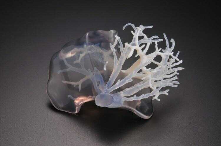
What is additive design?
Additive manufacturing (AM) is the process of joining materials to make three-dimensional objects from three-dimensional (3D) model data. AM involves adding layer upon layer until the product is completed.
Difference b/w Additive and Subtracted manufacturing:
Non-Subtractive Design Wrench Tool (incompeleted) :
In the start, I have known about additive design from the help of youtube tutorials and search engines and my local instructor is also telling me about this design. I have many problems understanding this design but finally, I have thought about this design and I have made a wrench tool.
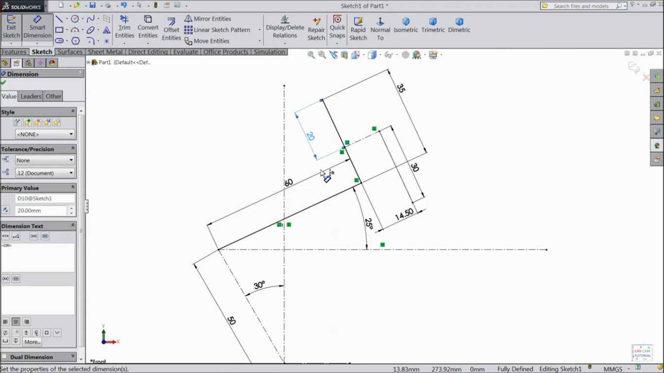
This is the first part that I am sketching at solid work software.
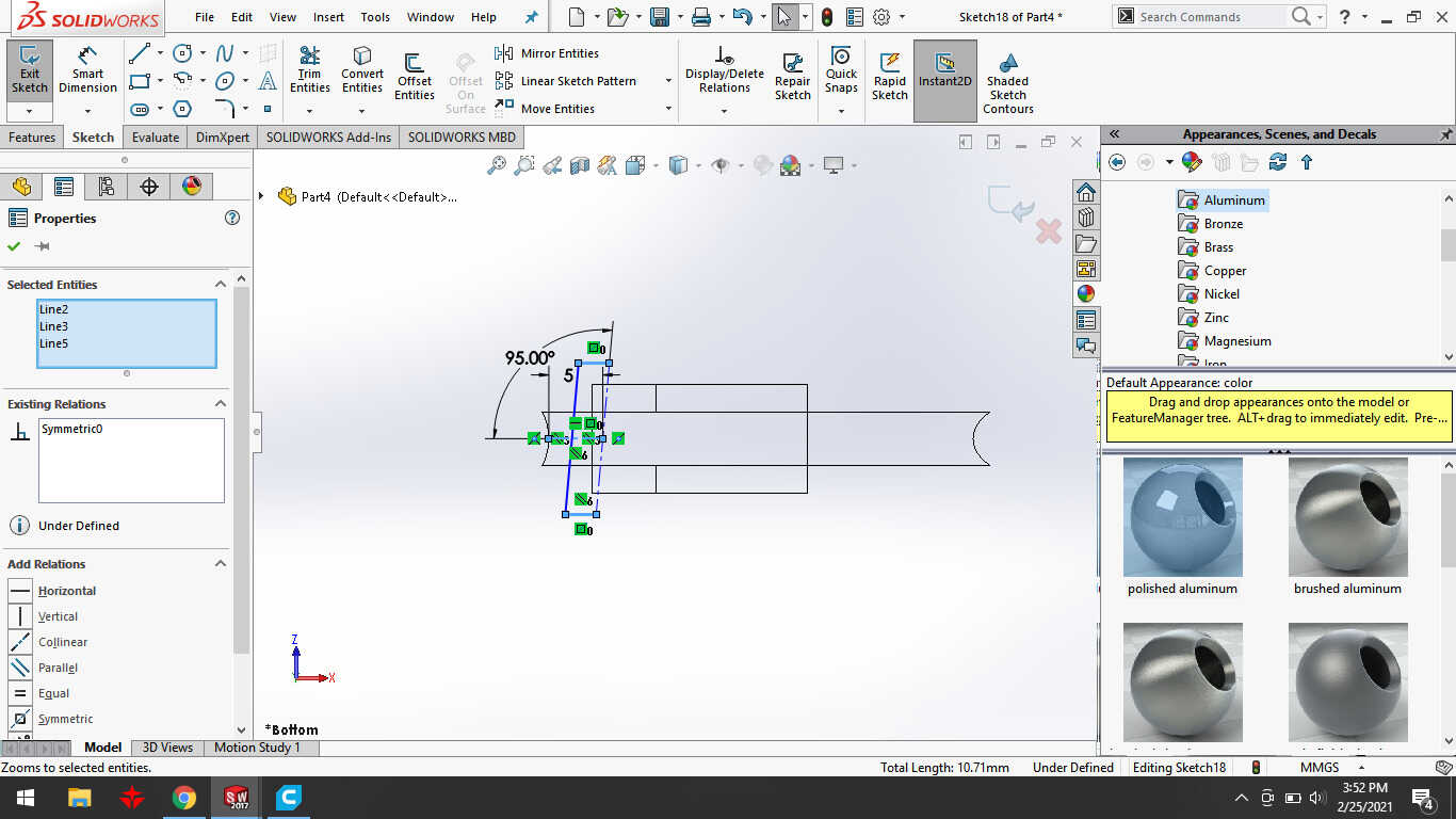
This is the second part of the model that I have sketched.
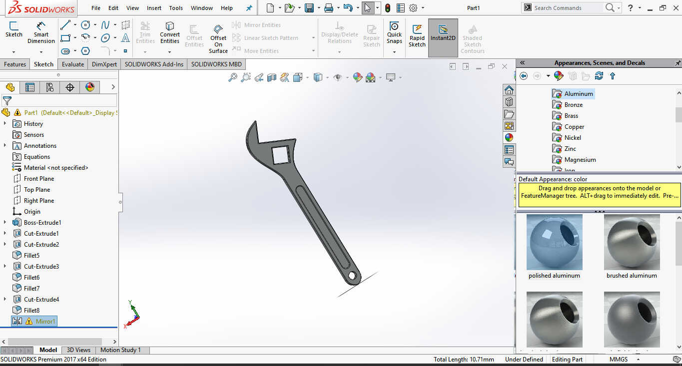
I have extruded the first part to create 3d model.
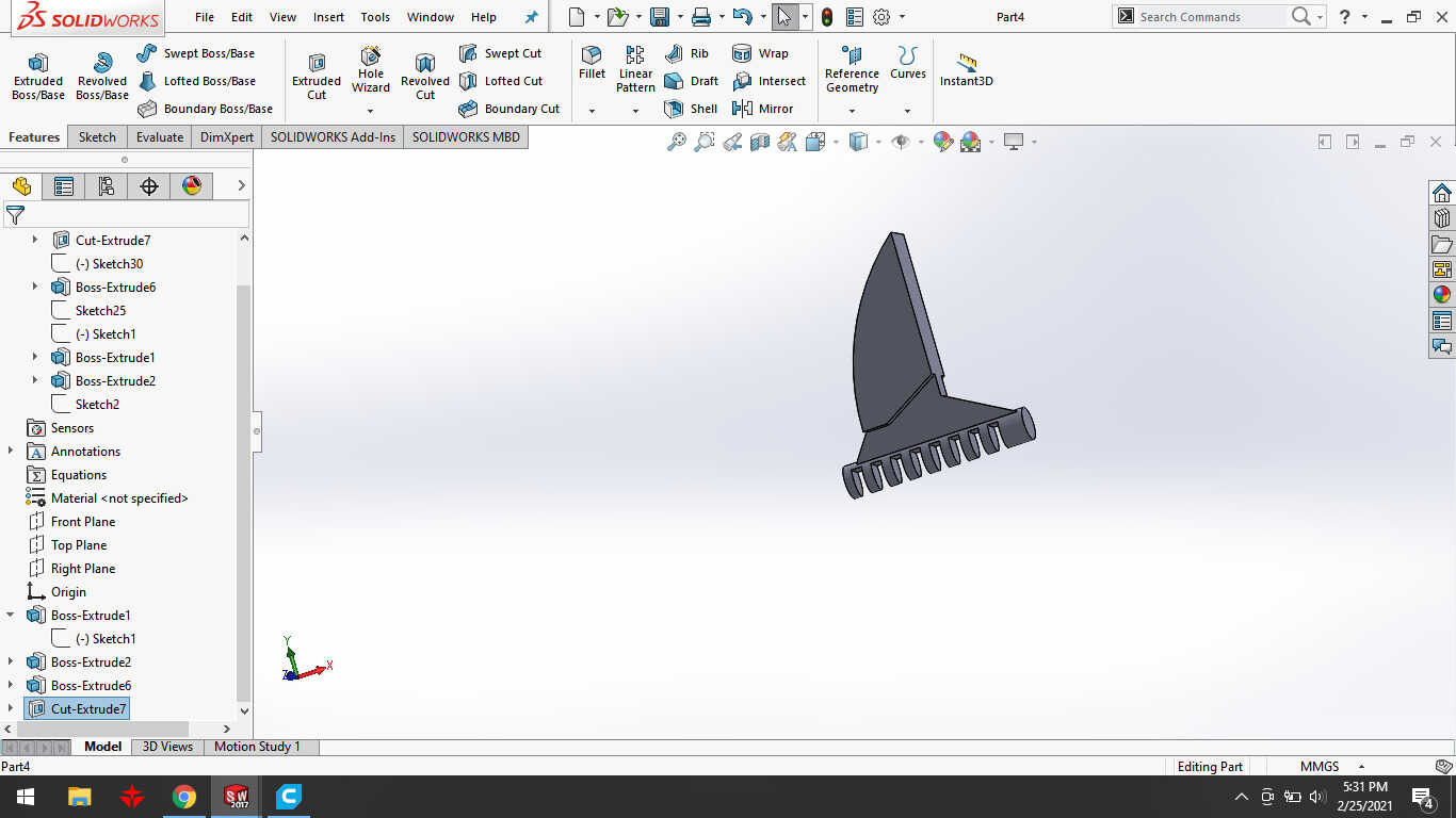
This is my second part of 3d model.

The third part of the wrench tool is a worm screw that is fixed inside the tool for adjusting the size.
I have completed the design of a wrench tool at solid work software.
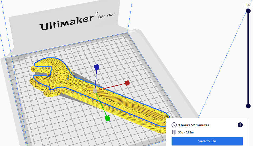
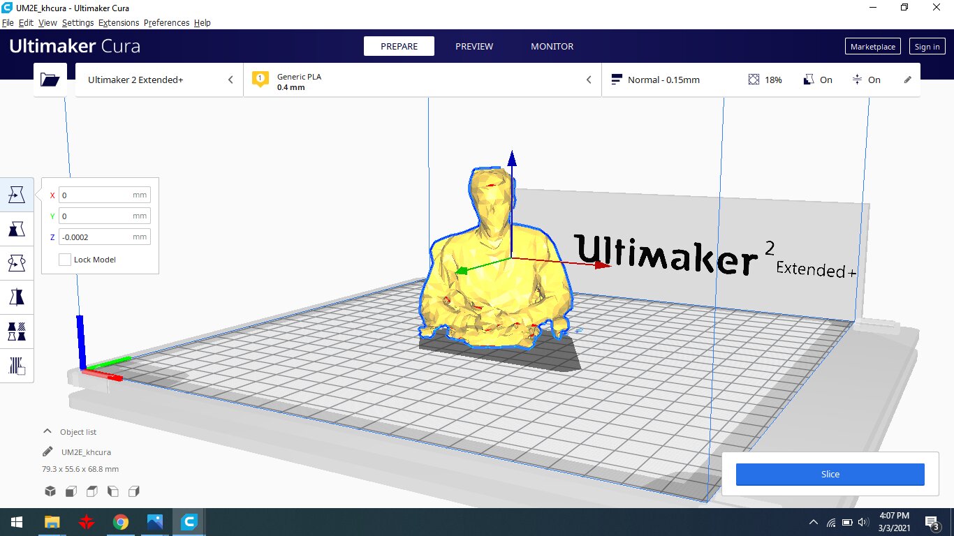
import solid work file into cura software and adjust the setting.

I have shown the nozzle diameter and file name that gives the 3d printer through SD card in a form of g.code

My design has wasted because the printer nozzle revolved without print my design due to the break of filament.

My wrench tool has been completed. but not working due to some problems with my design.

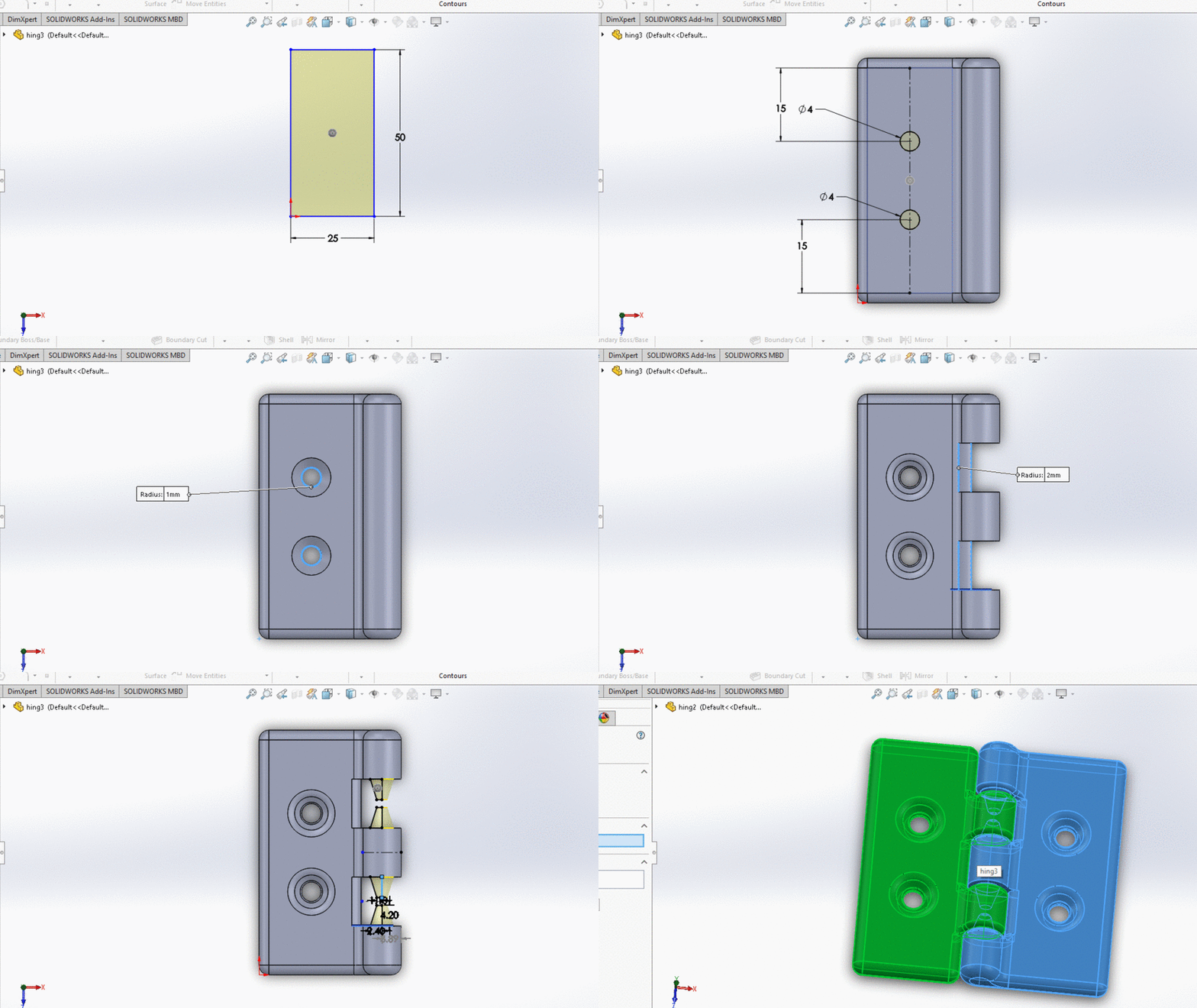
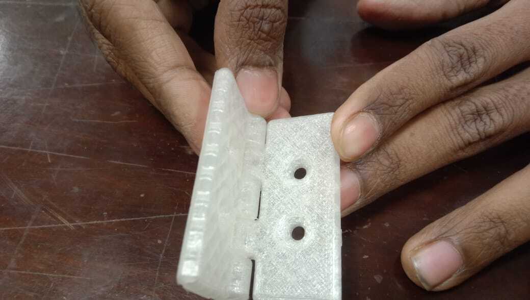
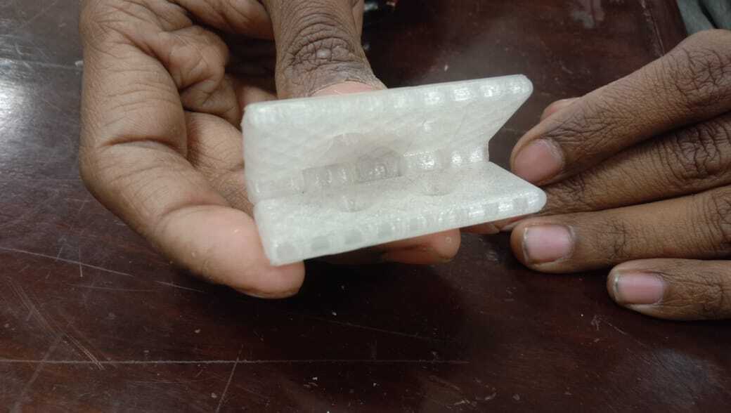
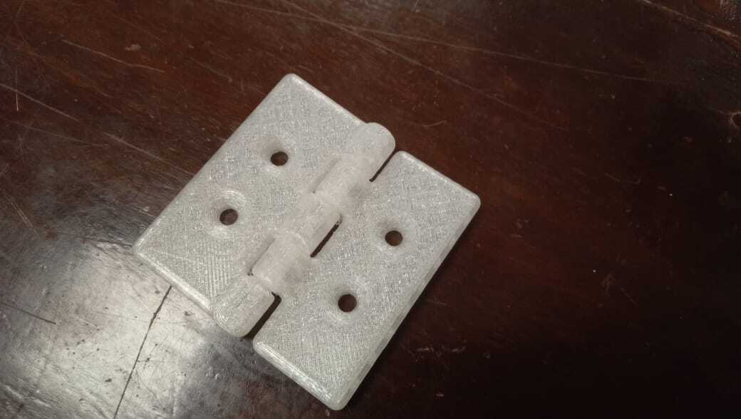
The 3d printed wrench tool is not working as I planned. Because the inner support of the wrench tool is stuck and unable to remove because of its design. As I spent too much time designing and printing of wrench I changed the project and start designing the door hinge because it covers the additive manufacturing requirement and takes less time to complete. It takes less time to print because the total weight of the door hinge model is 8 grams.
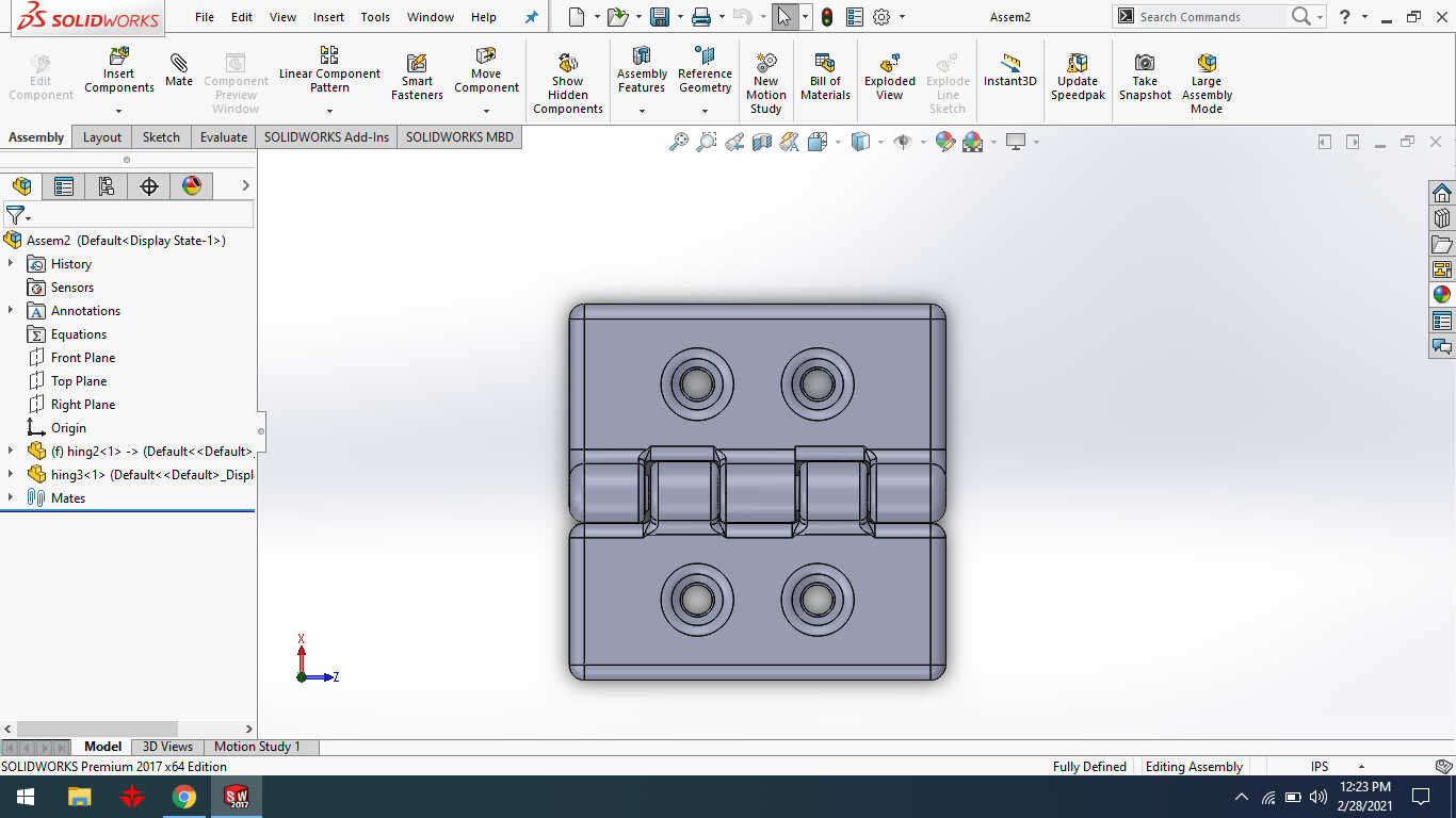
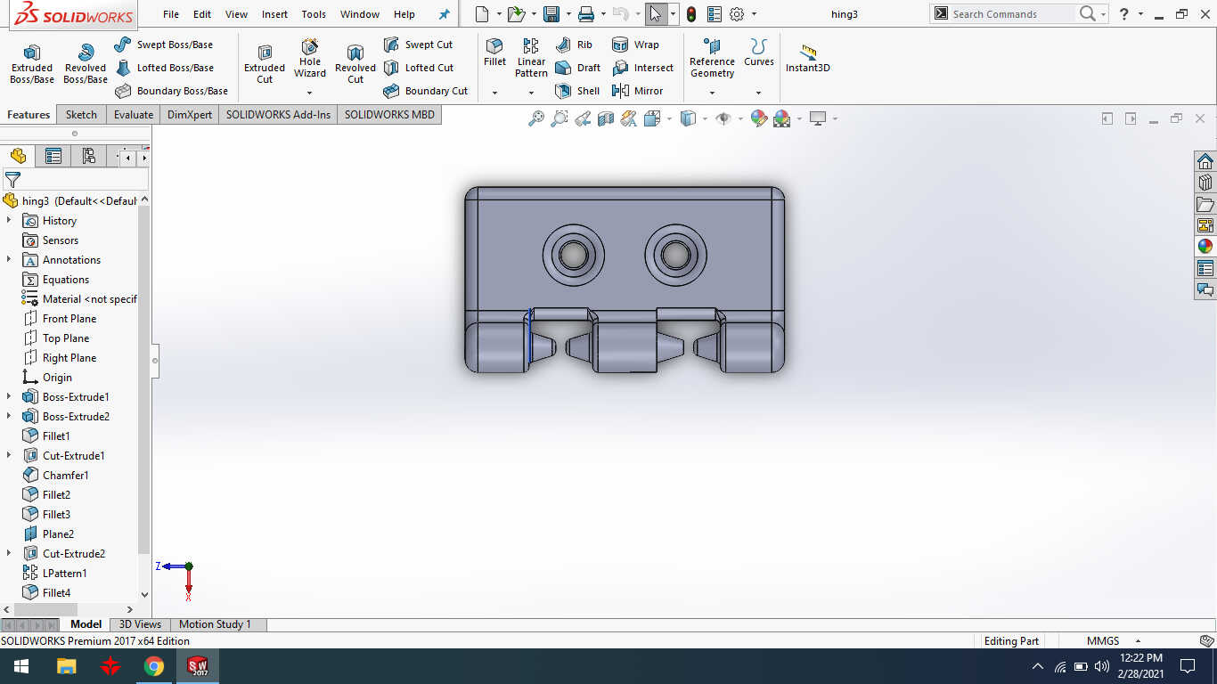
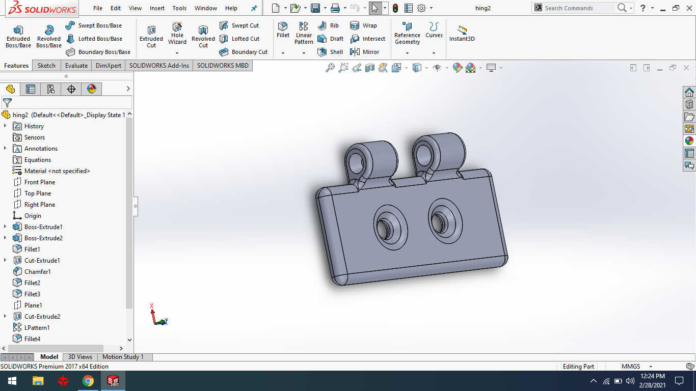
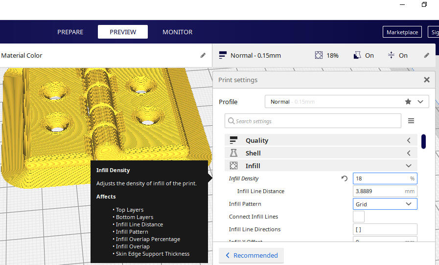
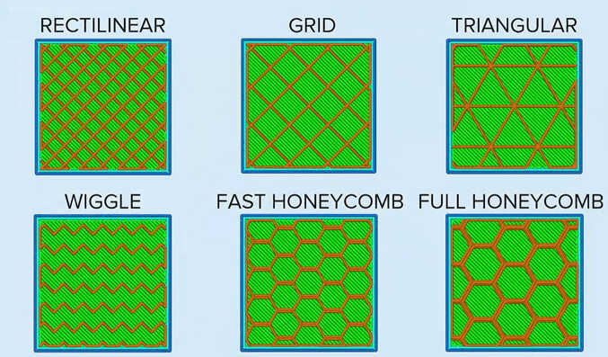
After completed my solid work design then I have to export it on cura software and adjust the settings. In this image, I have adjusted infill density and infill pattern. According to the design,I can change the different settings of the infill. But in this project, I did not need to change another setting.
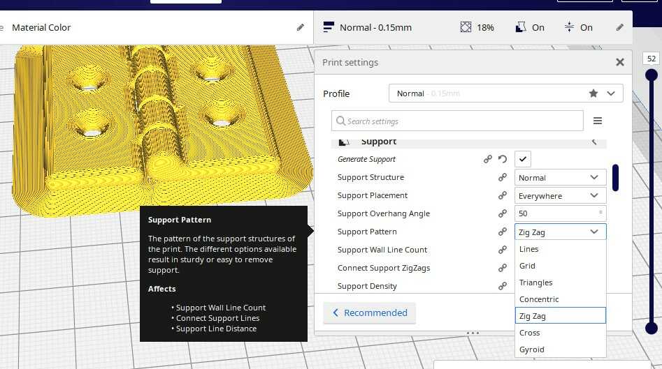
In this image, I have defined the support settings. I did not need to change the support set in my design because Supports in 3D printing are essential to print objects with overhanging parts but I can change the support settings according to the design.
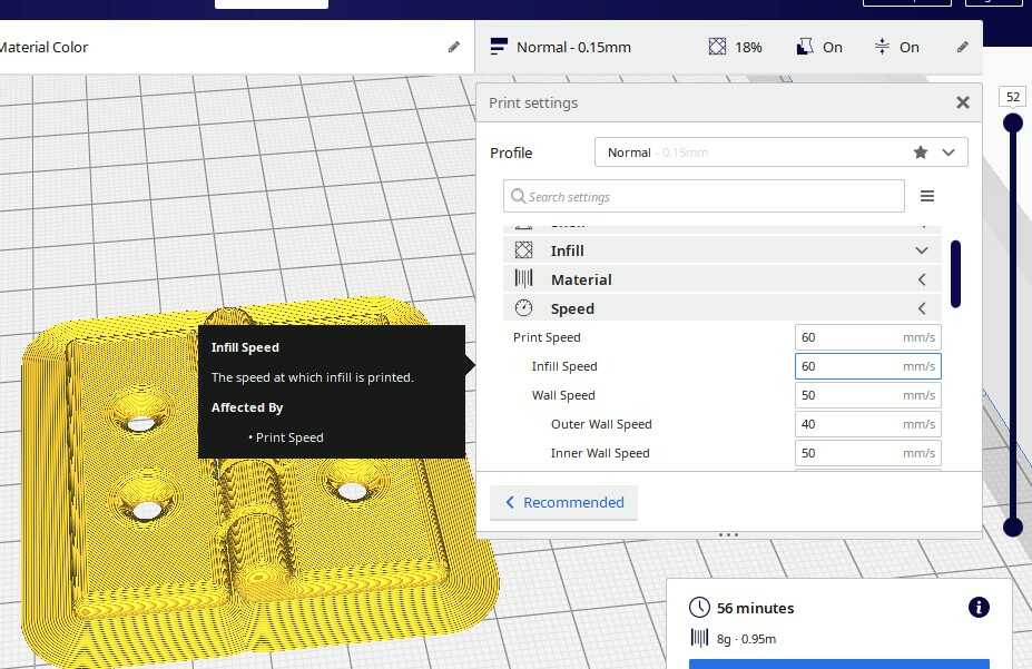
I have changed the speed of infill in my project.
Learning Outcomes:
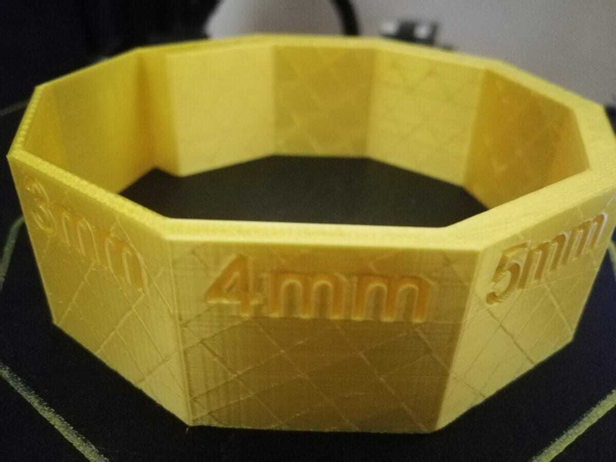
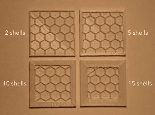
I have defined the set of shell size and no of shells in this image.
3D Printer Maintainance:
3d printer filament has broken during printing my design. So I have put the filament in the extruder.

I have cleaned the nozzle of 3d printer because the print was sticking on hotened and the plastic was burning.


This is a filament layer of Ultimaker 2+ extended.

I was set the nozzle temperature at 210C. I have used PLA (Polylactic Acid) filament. PLA is a popular 3D printing plastic material that features a lower melting point and more shallow learning curve for individuals new to 3D Printing

Task:02 3D-Scanning:
The second task was to 3D scan an object and print it(optional).There are mainly three ways to scan an object, which are:
1)Capturing multiple clicks from different angles and processing the images in software.
2) 3D scanning with Kinect device.
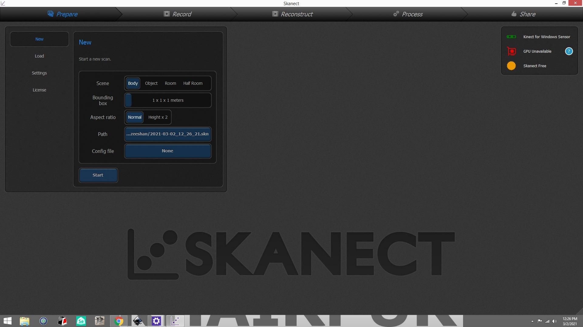
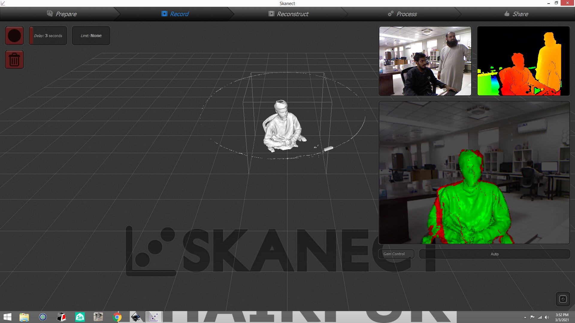
Use skanect software to perform the following steps and generate a stl file:
1. Open Skanect software, on top right check if the Sensor is connected properly
2. Go to "New" tab, click "Start" button
3. Position yourself accordingly while looking at the bigger screen of the 3 screens shown on the right side
4. Press the "Record" button
5. Once it starts recording, rotate yourself in either Clockwise direction or Counter Clockwise direction
6. Make sure that image is showing "Green" markers for most of the scanning area
7. If some are left unscanned, stay in that position for a while until the while portion becomes "Green"
8. As the scanning completes, press the "Stop" button to stop recording
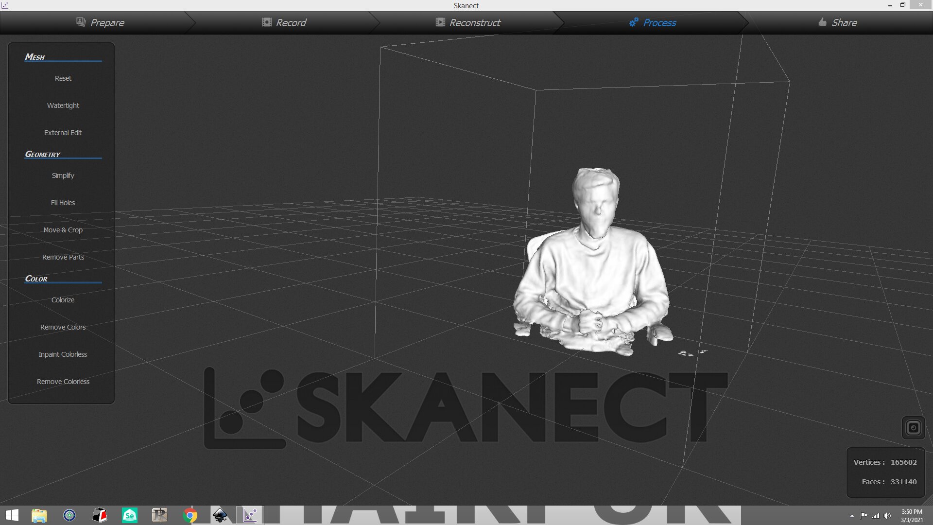
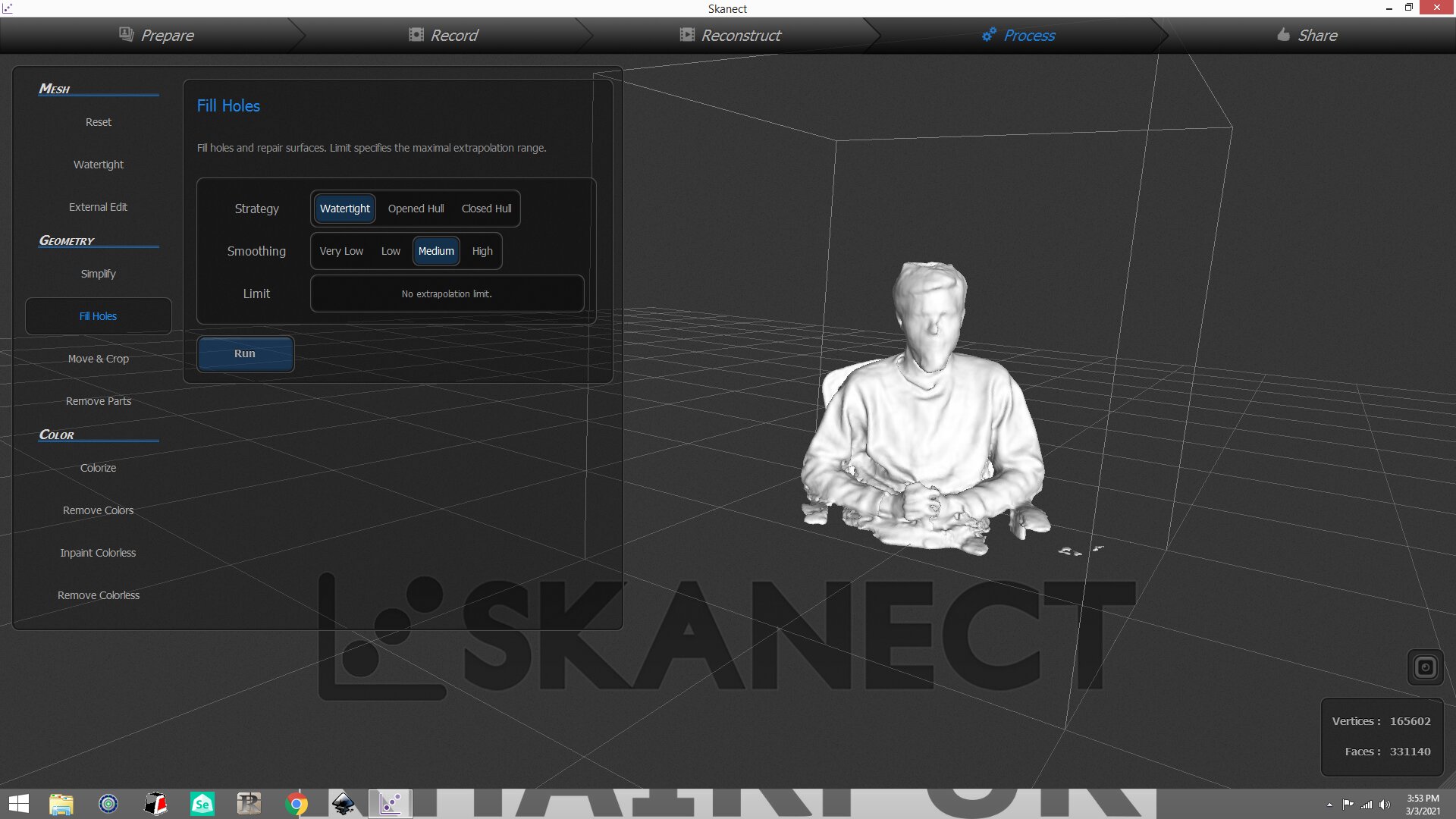
9. After recording, go to the "Process" tab and select "Fill holes" to make the model more appropriate, and press "Run"
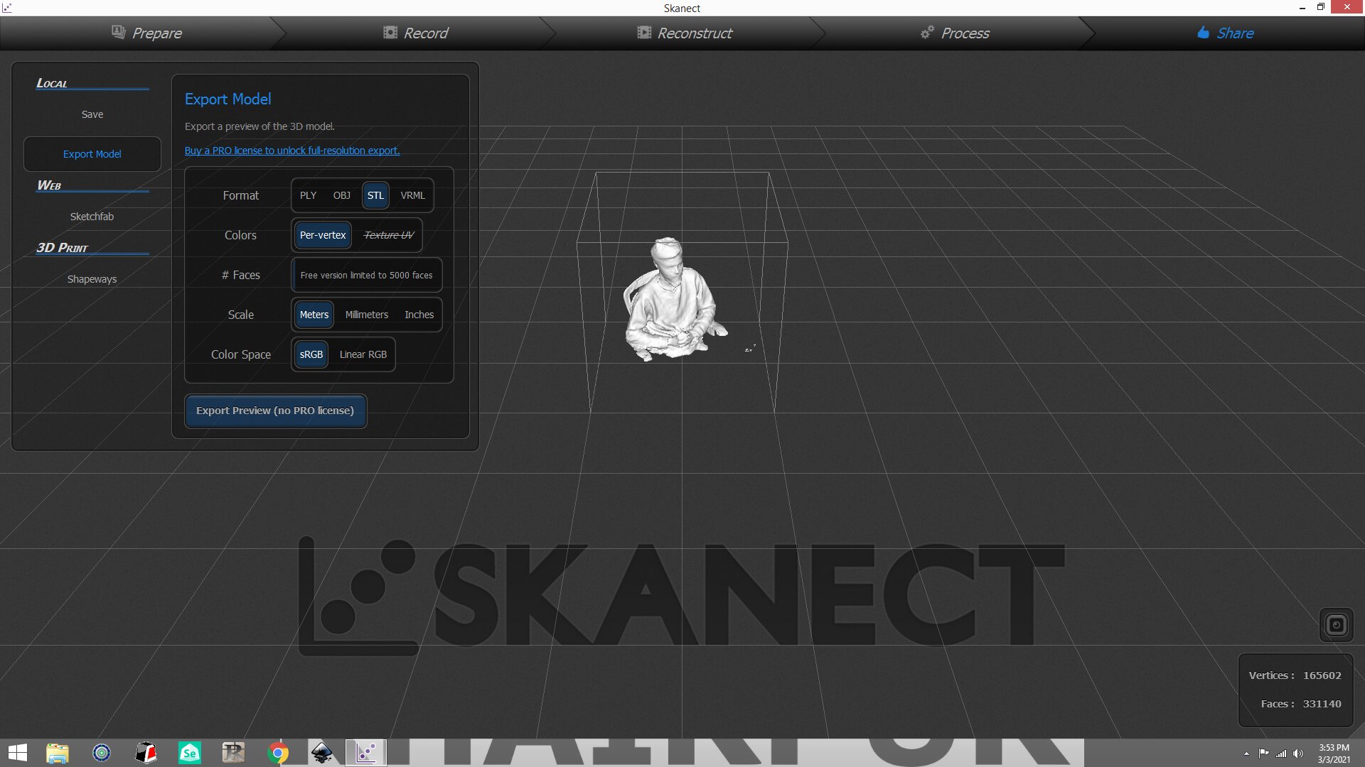
10. Now export your model as a .stl file and make sure to keep the units in Millimeters.
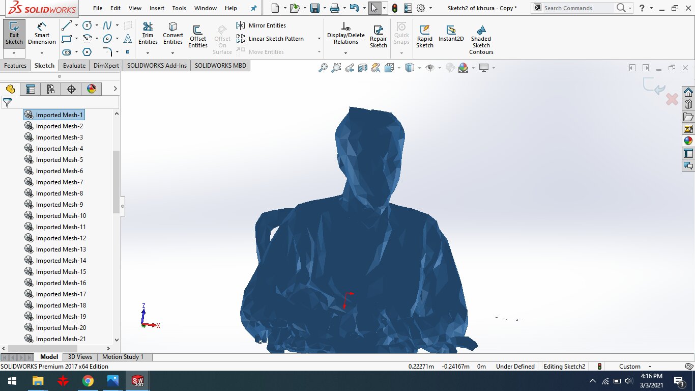
here is the command for files upload
"Click here"to download all files of this week