BACK TO HOME PAGE
WEEK 4
Electronic Production
Group Assignment:
characterize the design rules for your PCB production process.
Individual Assignment:
1)make an in-circuit programmer by milling and stuffing the PCB
2)test it, then optionally try other PCB processes
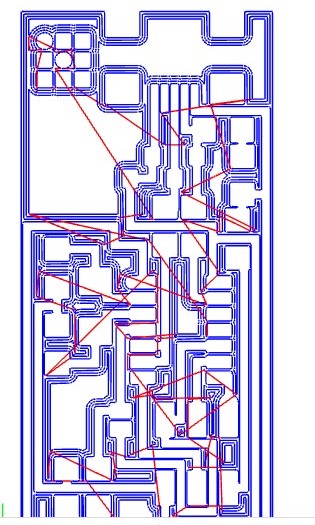
First, I download circuit diagram in png format from fabacademy 2021/ electronic production schedule/in circuit programmer/In system development/ATtiny44/Ali. I have downloaded the circuit of hello.ISP.44 board/components/traces and interior
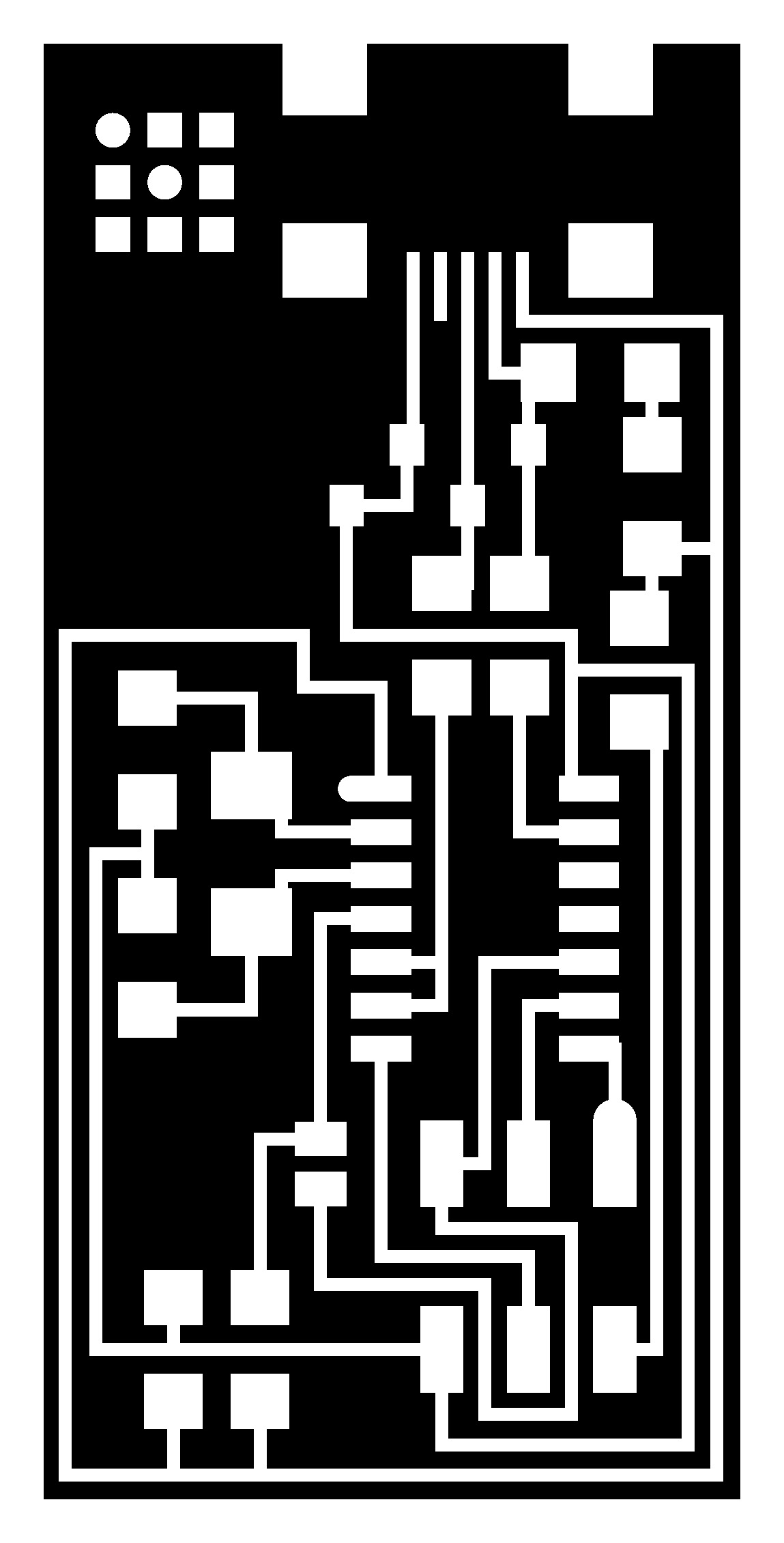
This is traces of circuit.

This is the interior of circuit.
I have included 6 holes in this circuit because I have available 2x3 pins connector.I have used 1/32 bit for holes and cut the PCB board and 1/64 bit has used to make traces of PCB board.
MODS STEPS:
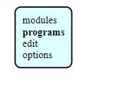
1)First, go to the mods website
2)then press right click and go to the program.
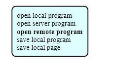
3) Then go to the open server program.
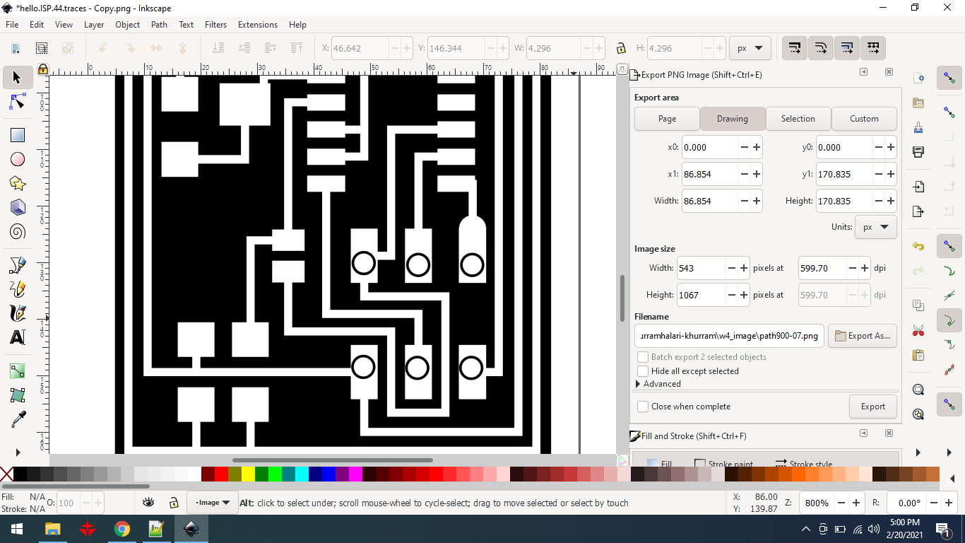
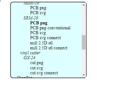
4) then click on pcb png that is in SRM 20.
5) then I press select png file button.
5) After your file is upload then you will set the x,y,z axis at zero position then press the calculate button and your file will automatically save.
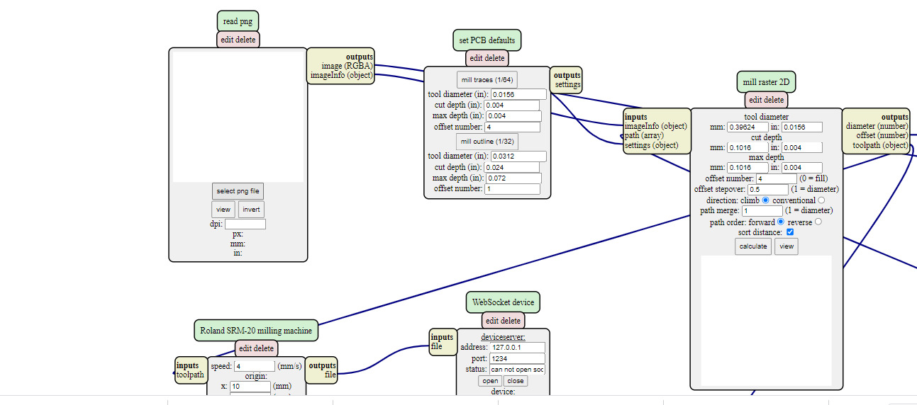
generate file from png to rml format at cba.mods.
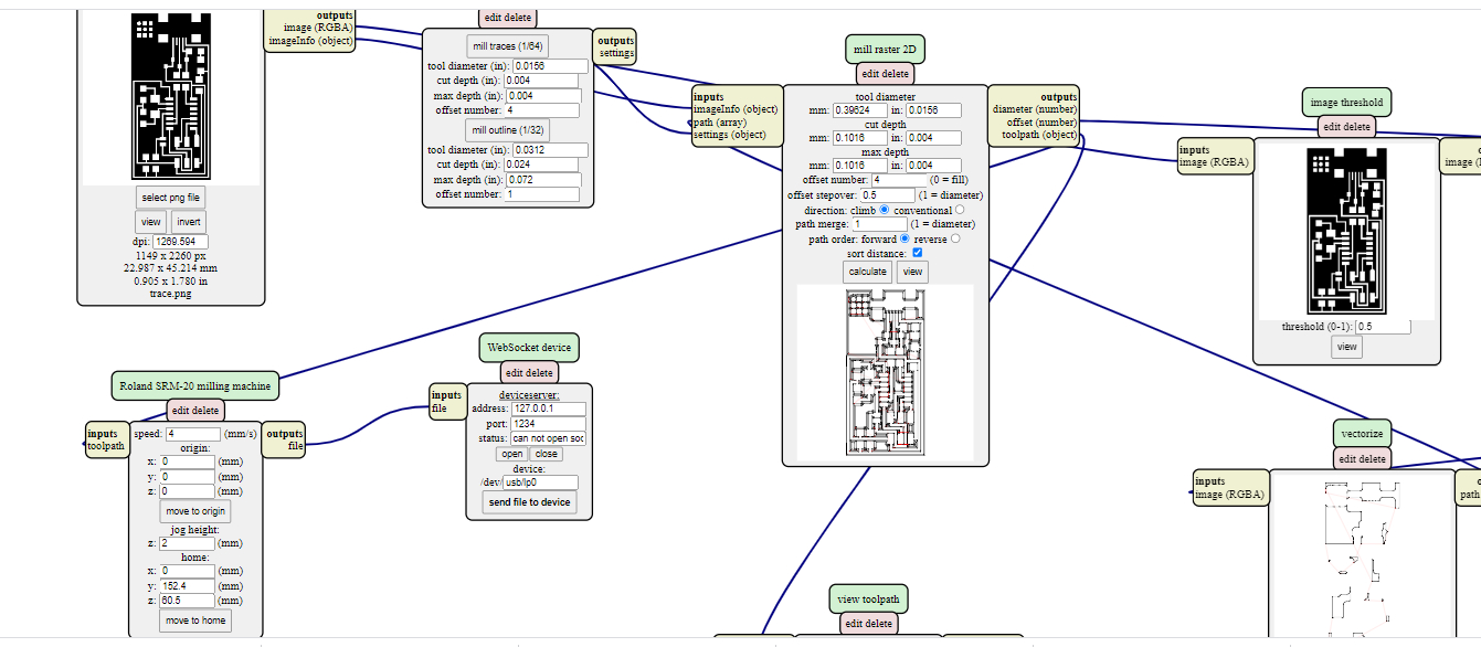
Save rml file for mill the circuit.
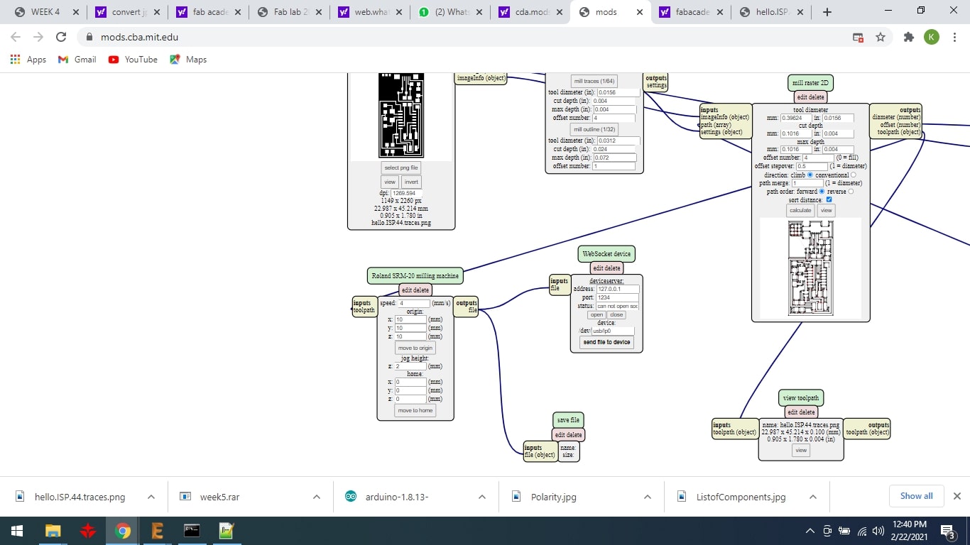
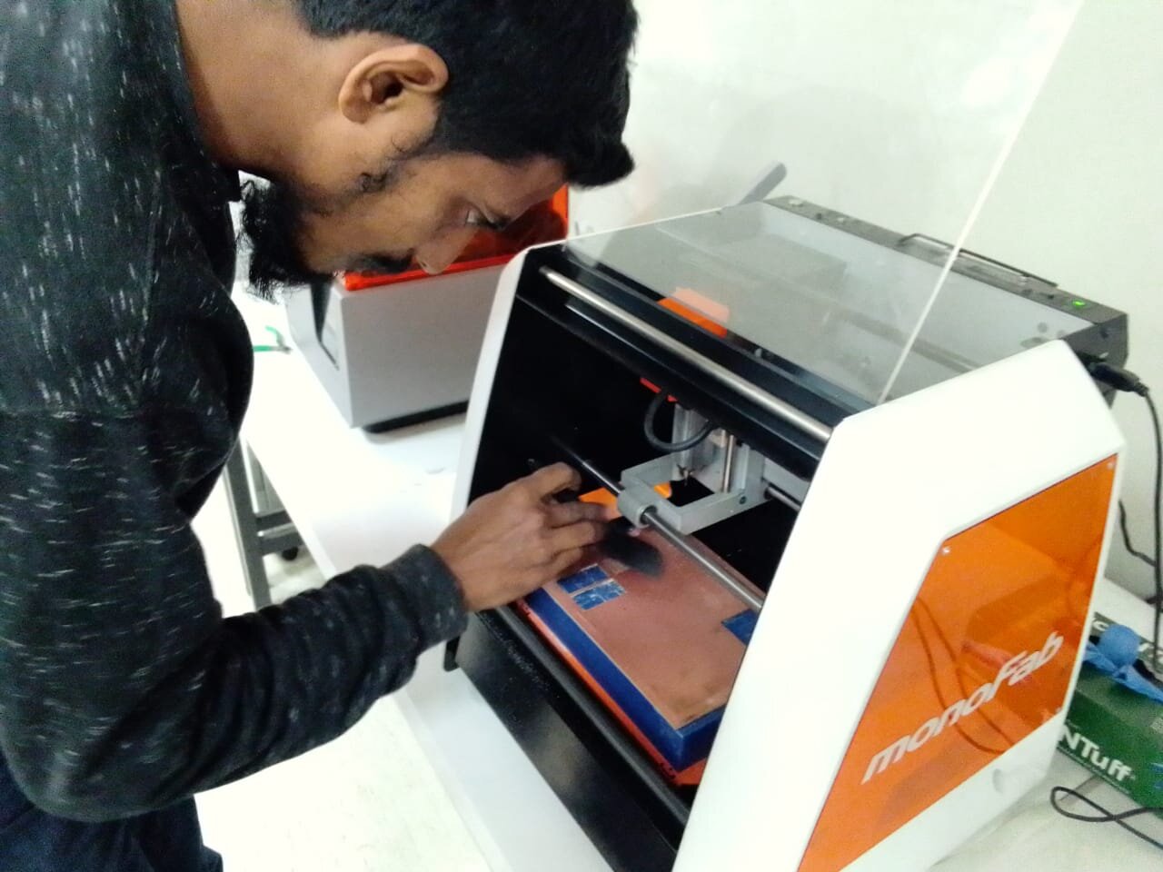
After a long process my file is ready for milling machine is Monofab.
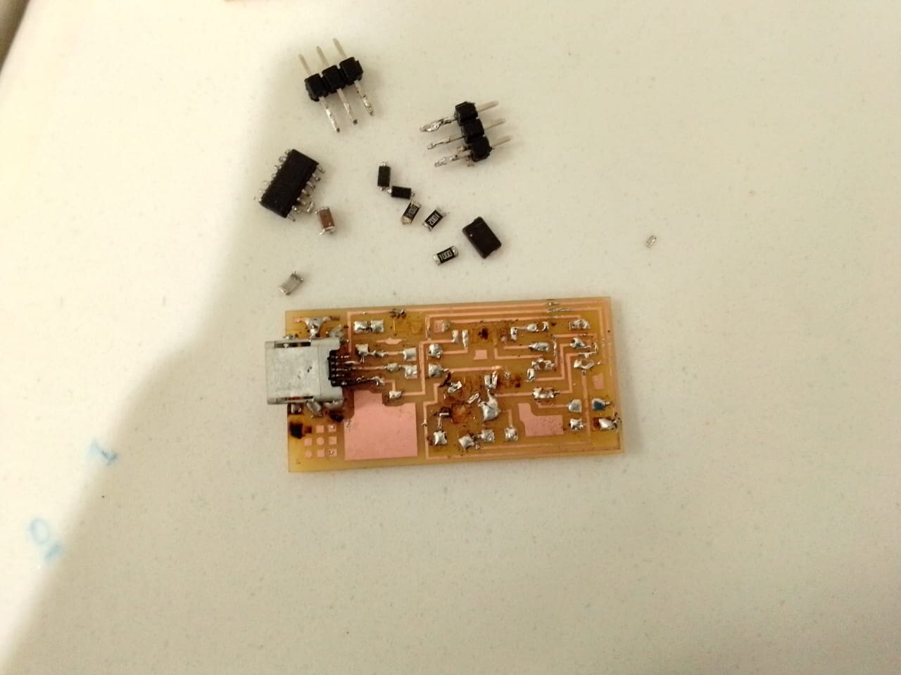
COMPONENTS LIST.

When I have given file to machine then machine has start the process of milling but after a few seconds router bit had broken.then I changed the bit 1/64 and then my circuit milling is compelete.
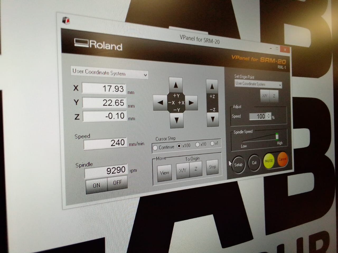
In this image I have show the rpm of motor and axis of x,y,z. The software of monofab machine is v-pannel.
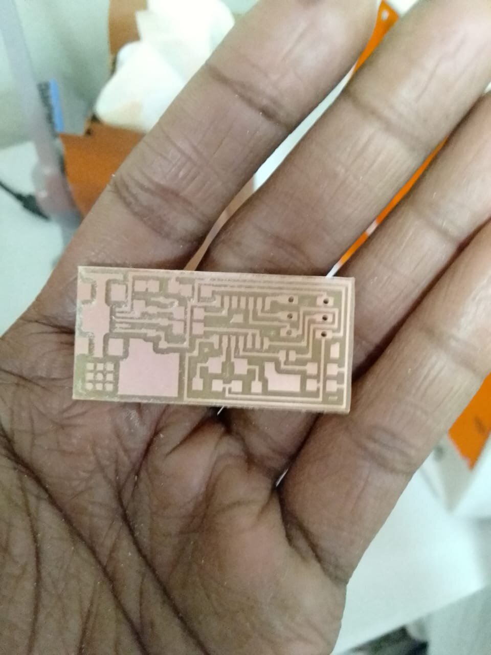
Machine has compeleted the mill of PCB circuit and also I have create holes in PCB circuit.
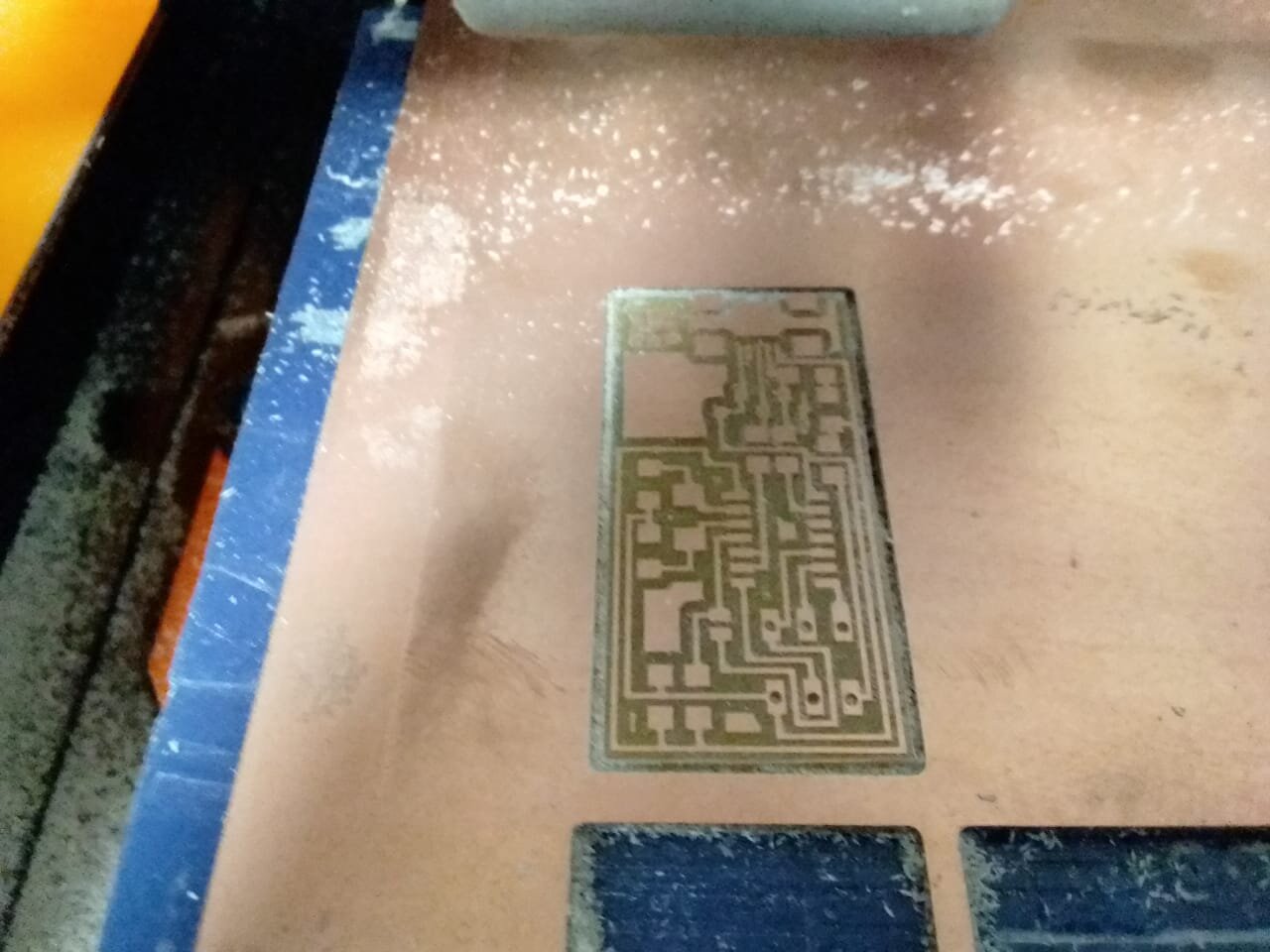
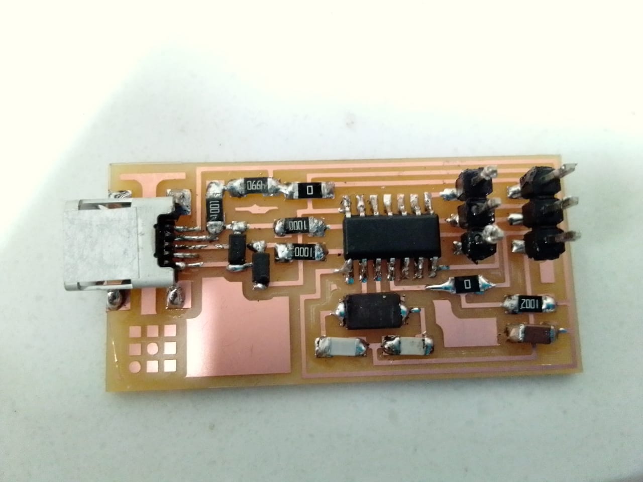
This is my PCB circuit.
when I have solder at my circuit during the soldering my circuit had wasted due to the some layers scratch then I desolder of whole circuit.because my circuit layer had wasted but components had safe.
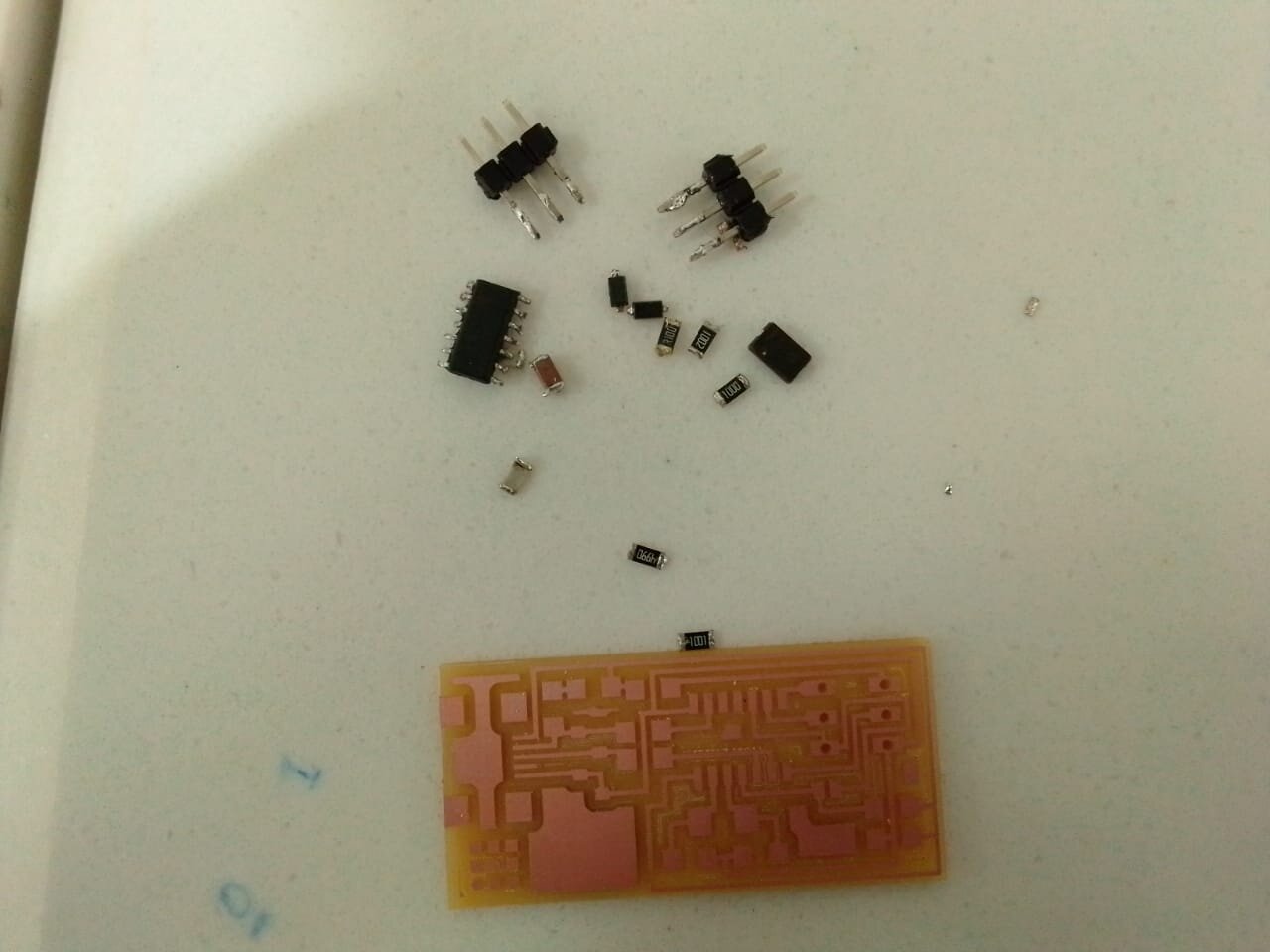
This my new PCB again I have given rml file of traces,interior and holes and after process of machine this is the result of my new PCB layers.
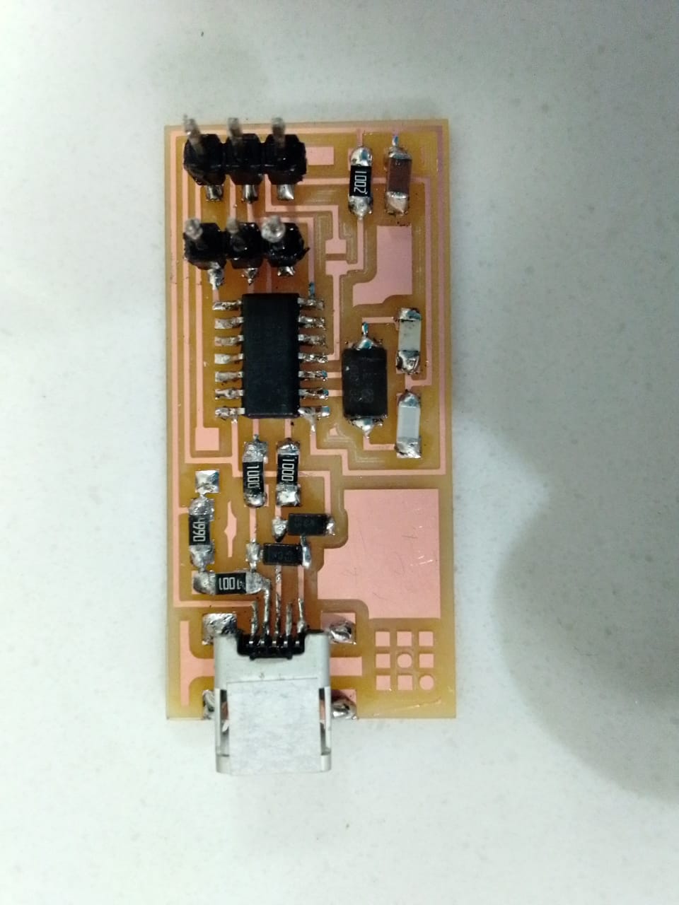
So finally I have compeleted my job to make a pcb of isb board.Before I have not a prior experience to soldering of smd components.But when I try to do this work then I have able to do this task.
Programming Process:
For burning program in development. I use linux because it is easy to work on it. We dedicate our Lab one pc for Linux and installed Ubuntu in it.
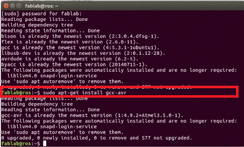
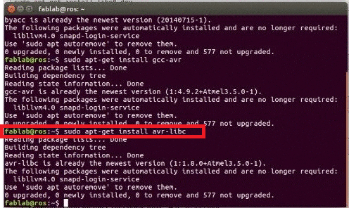
Installation of avr, GCC and libraries
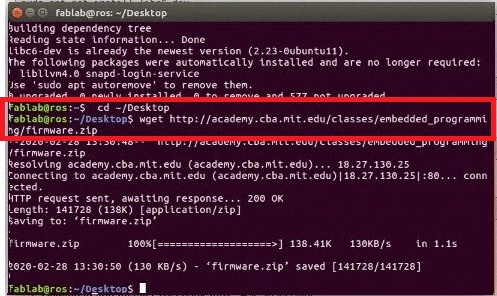
to use the wget command save firmware
Connecting both development board on PC one for developing and other for 1st one development
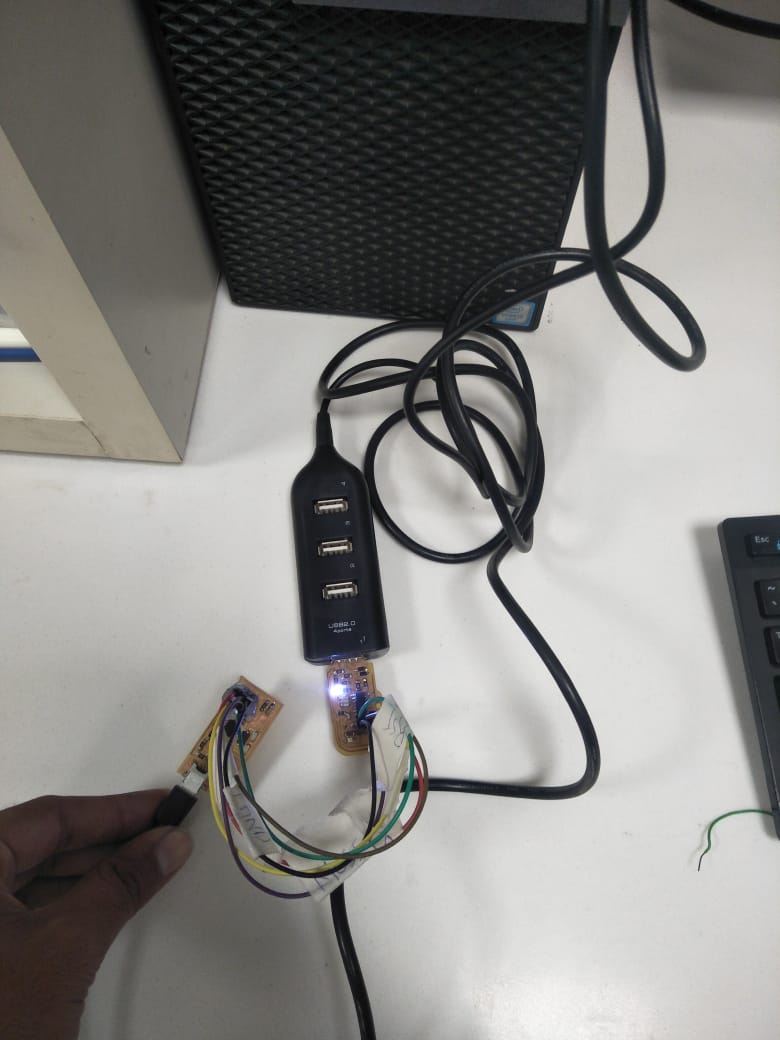
a development board is developing by development board
after connecting both cables I locate FabISB folder which is on Desktop and run command "make clean" and "make hex"
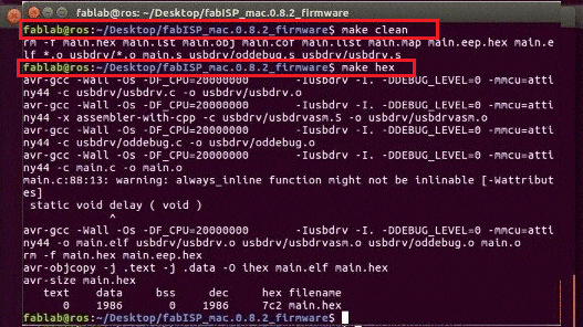
make clean" and "make hex commands"
to set fuse I used command "make fuse" then program the board we are using "make program" command
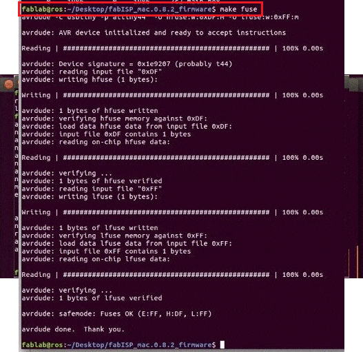
setting up fuse
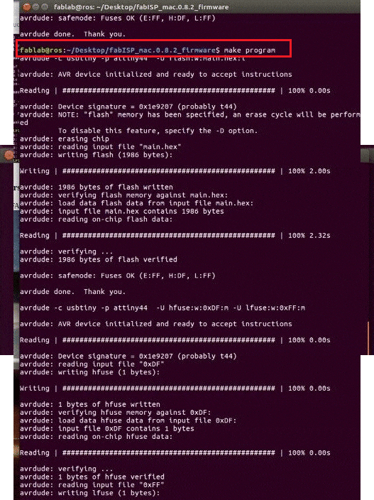
make program
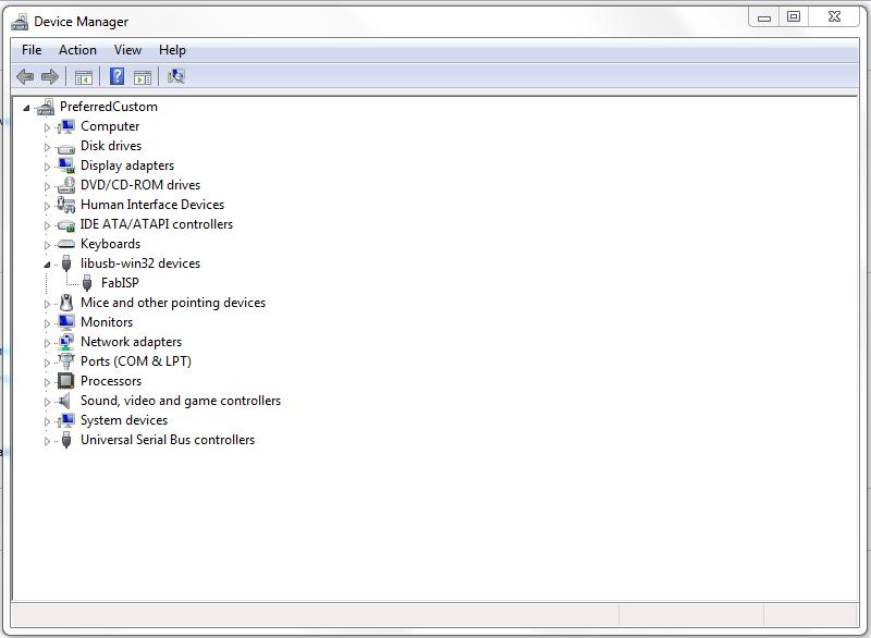
Now to check either it is working or not
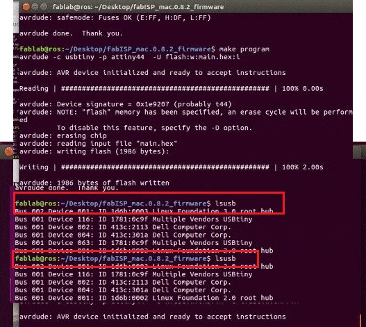
It is shown two development boards are connected
This is the result of burned programmable IC now it is ready to program another controller.
Group Assignment:
For our group assignment I learn the specs of the PCB milling process, mill the line-test file using the 1/64 tool bit and test the parameters of our tool.
Fab Modules
Using FabModules we set the input format to image (.png) and uploaded my file. The traces file should now be visible. Then set the output format to Roland mill (.rml) as these are the machines we use. Finally in process set to PCB traces (1/64) for the traces file and the repeat the process for PCB outline (1/32) for the outline (see below).
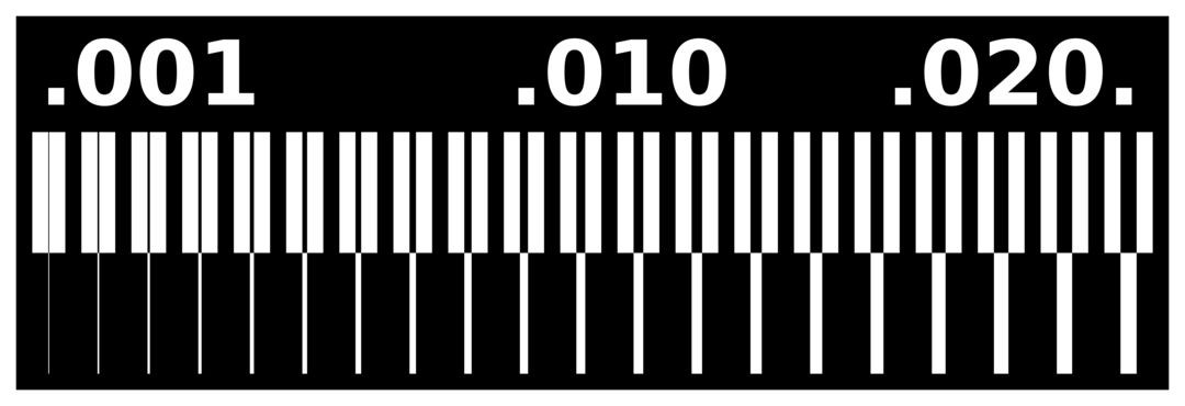
These are the traces we will mill with the 1/64 tool:

And this is the outline we will cut with the 1/32 tool:
Output Settings
We then modified the settings on our input on the right, much as is showed in this video selecting the output machine to our SRM-20 Roland Mill.
For our machines we made sure the x (mm) y (mm) z (mm) and xhome (mm) yhome (mm) are all set to 0.
The only exception is zhome (mm) which we add a 5 value. This is specific to our machines, and makes sure the spindle will raise the tool before returning to the origin when finished milling. Without this zhome margin, the tool risks scratching its way back across the surface of the board ruining both bit and board.
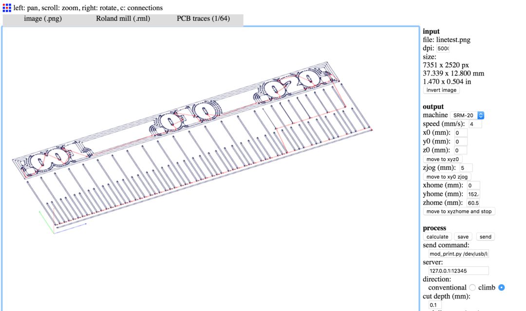
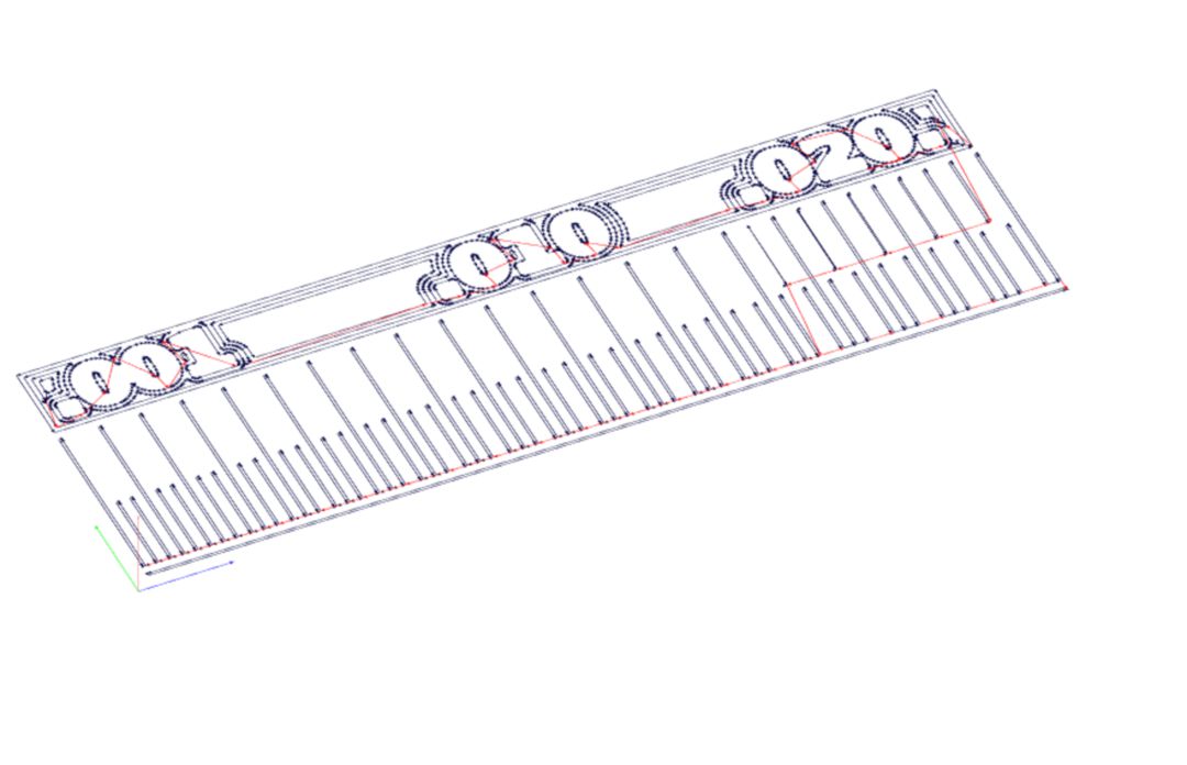
Below you can notice the 4 offsets the simulated tool path makes, and how with a 1/64 bit it will not completely define the traces which are closer together.
Milling the PCB:
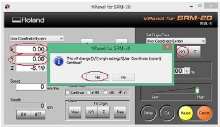
Select origin to x/y and z axis by changing values of x, y and z axis from where it should be start.
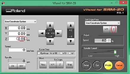
Adjust drill bit z axis until it touches PCB board,then Change Z-Axis value little bit to dig PCB board slightly and then set new value of Z-Axis as origin.
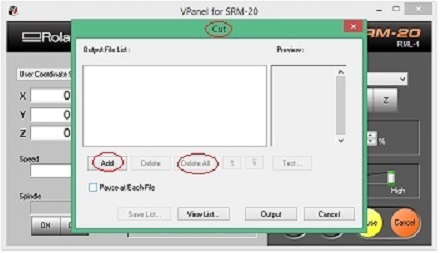
Click on "Cut" and locate .rml file which we want to use.
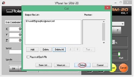
Click on "Output" to start the process.
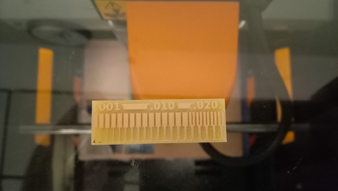
This is my group assignment for the pin test.