BACK TO HOME PAGE
WEEK 10
INPUT DEVICE
WEEK ASSIGNMENTS:
Tasks for a week
Task:01 To Add a sensor to microcontroller board:
During this week we have learned about input devices which are also called 'sensors'. The sensor is a device that converts a change in a physical quantity to a measurable change in electrical values i.e current, voltage, capacitance... etc.
The main task is to program different sensors using our own boards.
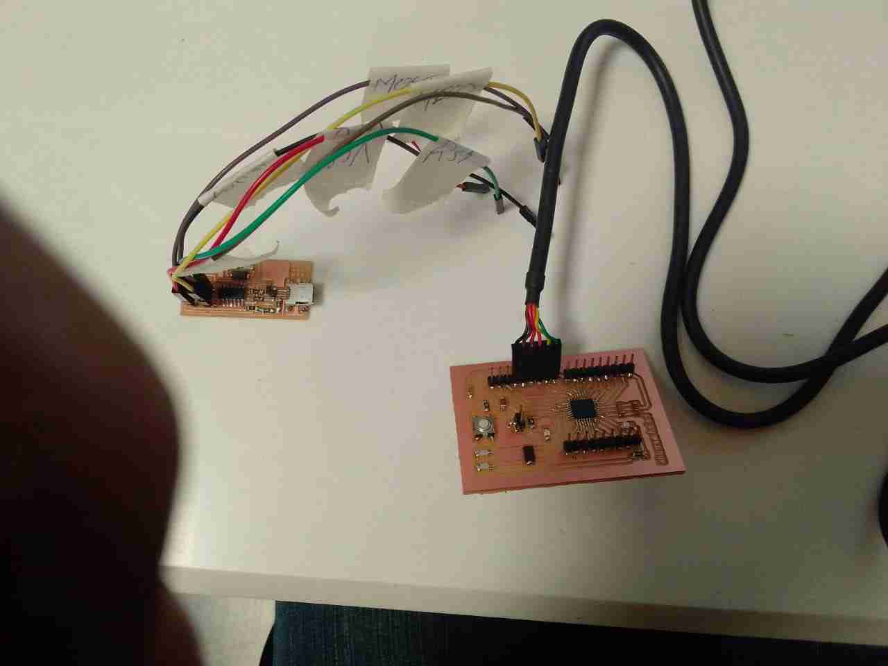
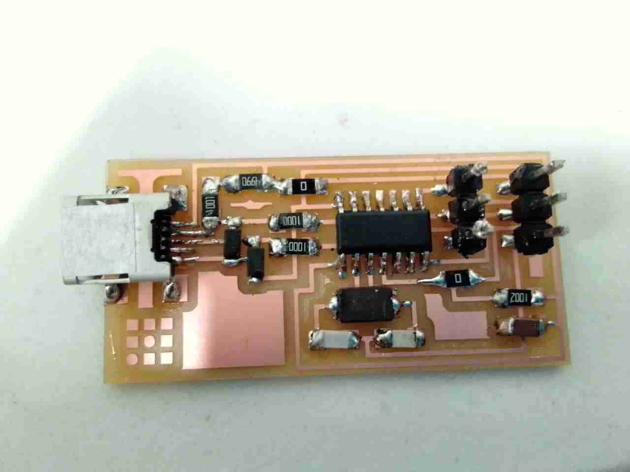
I used my General Purpose Board with Atmega 328P microcontroller chip, which I made in Electronic Design Week. I started by programming my Arduino using FAB ISP board following these steps:
Connections:
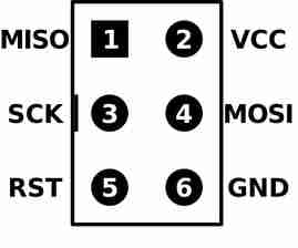
Using FAB ISP board In-System Programmer, allows the Arduino(Vastuino) microcontroller to be programmed and reprogrammed without having to remove it from the circuit. Programming any AVR microcontroller six wires are needed:
This is a top view of ISP headers:
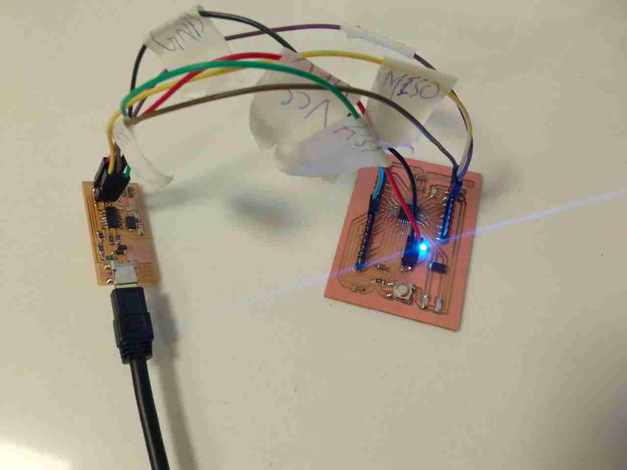
I used Attiny Microcontroller board with my Arduino(Vastuino) board, which I made electronic designing week.
I connected the ISP header to the Arduino pins on the PCB via jumpers:
Bootloader:
1.Change board settings as shown below then press Burn Bootloader.
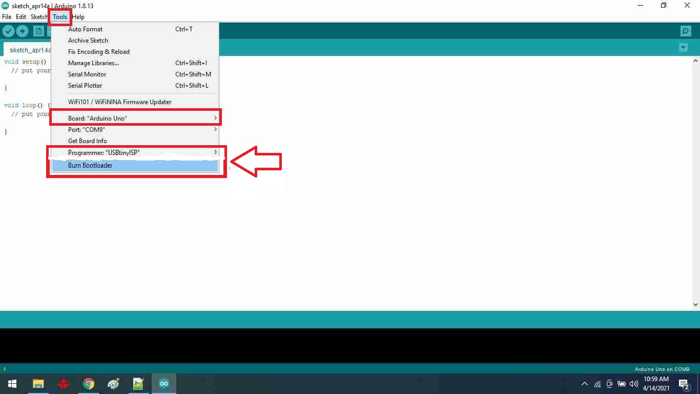
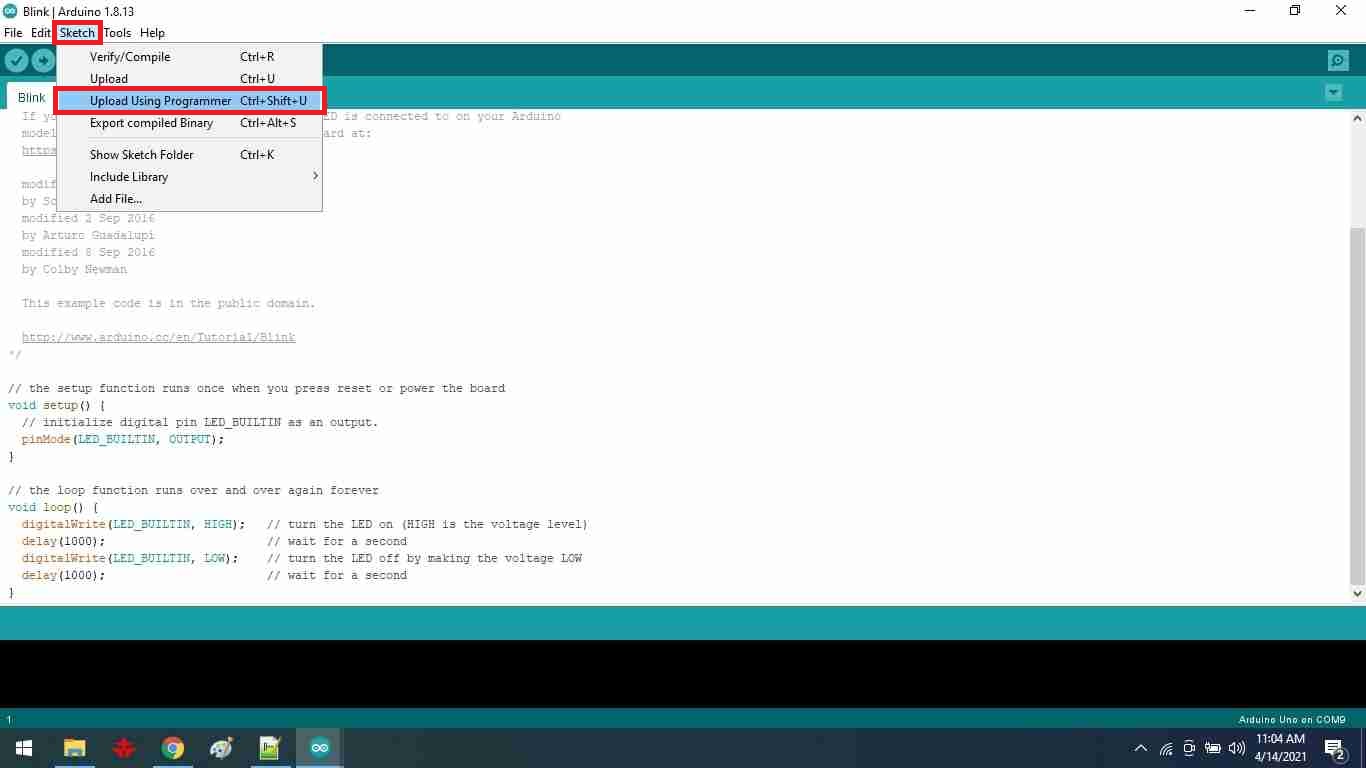
2.After that if Done burning bootloader message appears, that means your Board is ready to receive any code and you can upload this code as shown:
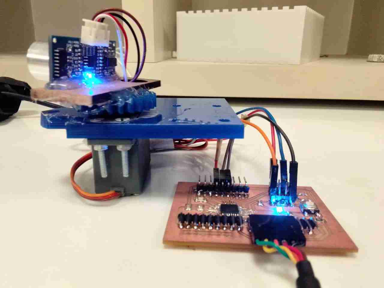
Ultrsonic Sensor:
I will use an ultrasonic sensor because I used it in my final project to measure the height of the smart desk. Ultrasonic sensor that sends ultrasonic waves at a specific frequency by TRGE pin, then ECHO pin receives the reflected wave. Through programing code you can measure the reflection time, then find the distance from the object by multiplying the time with the sound velocity 343m per second and divide it by 2 ( because the wave goes to the object and reflex from it).
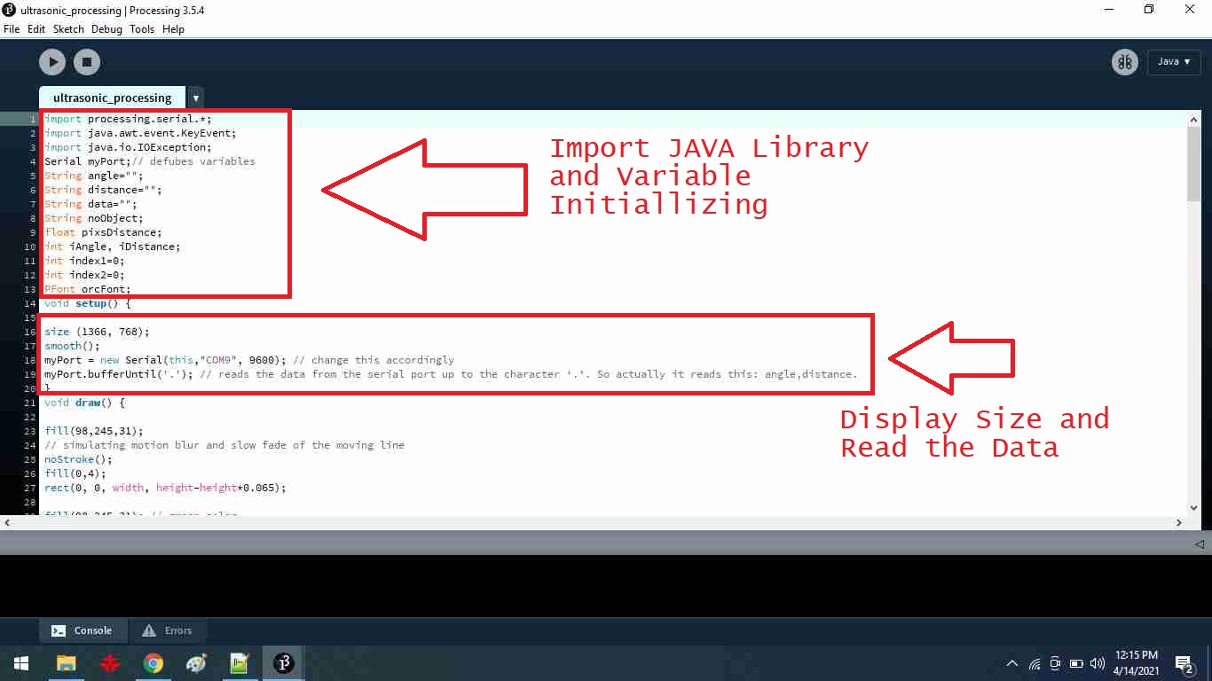
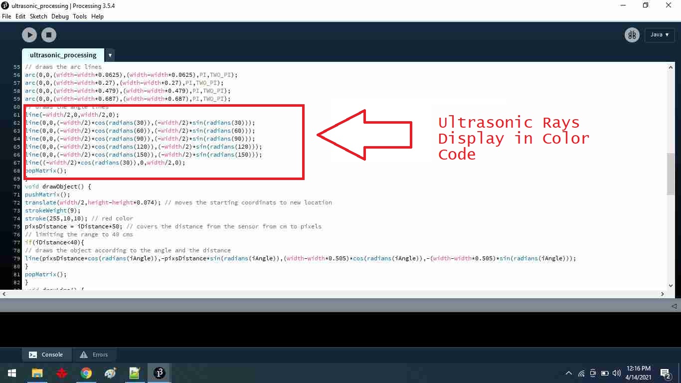
I wrote a code that measures the distance of an object and if it is between 10 to 40 cm the red wave will be shown on display and also I can connect the speaker at the output pin of the Arduino controller. Green waves show the distance is larger than 40cm. This is my code I explained each line within it by a command line.
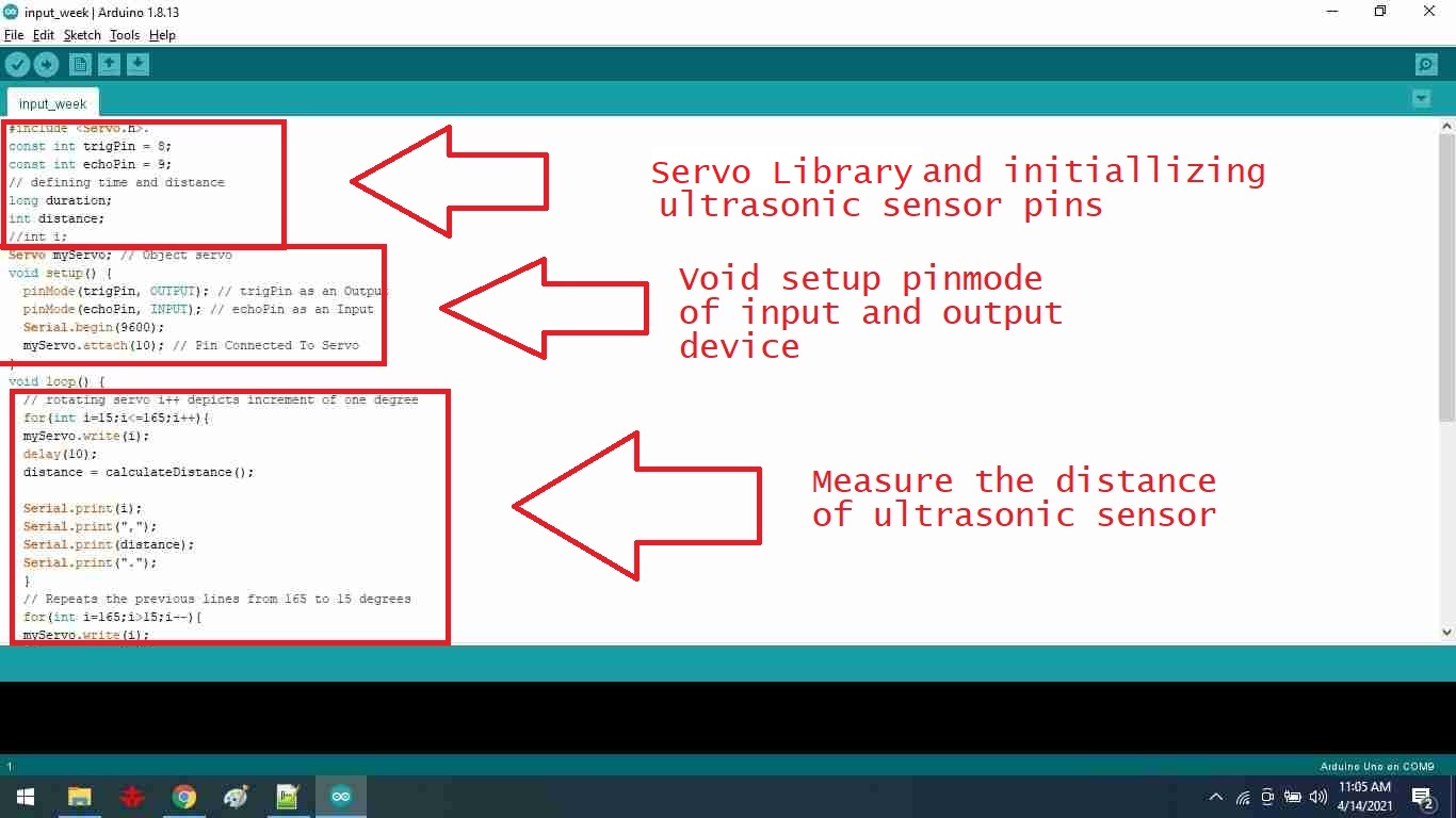
Servo and Ultrasonic code
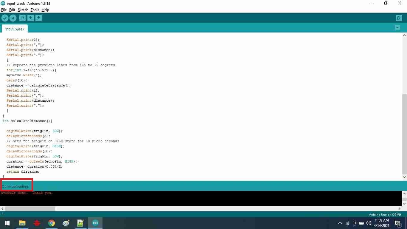
Done Uploading
Then I use FTDI cable to upload the code to the Arduino board.
After uploading the code I disconnected all wires and connect the ultrasonic and servo motor with my Vastuino Board as shown:
Watch the video
I begin by uploading the code for a basic servo motor movement. Then I downloaded the processing software, which I'm using to generate the obstacle reflection signal.
I created a program that generates a red and green signal. When an ultrasonic sensor detects an object, a red signal is produced in the output. A green signal is produced if the target is out of range.
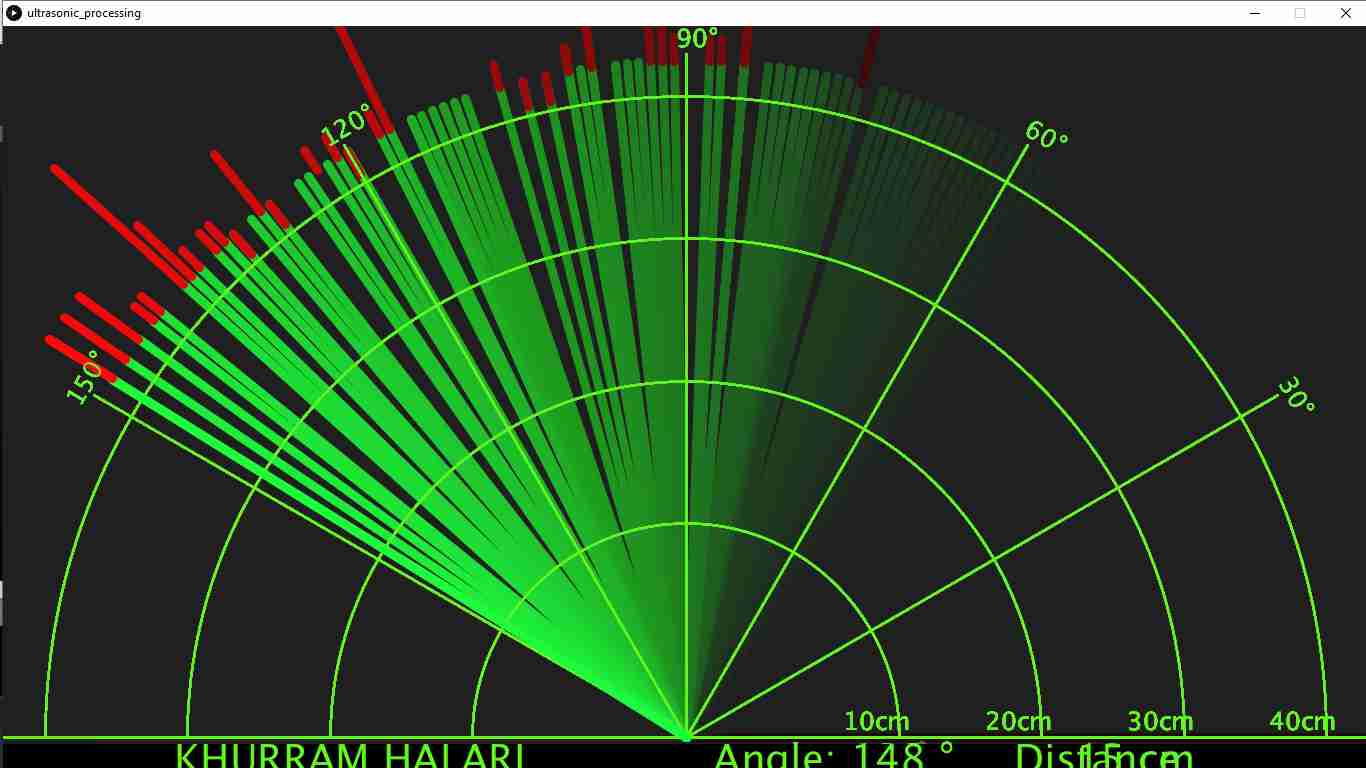
The object is now out of range.
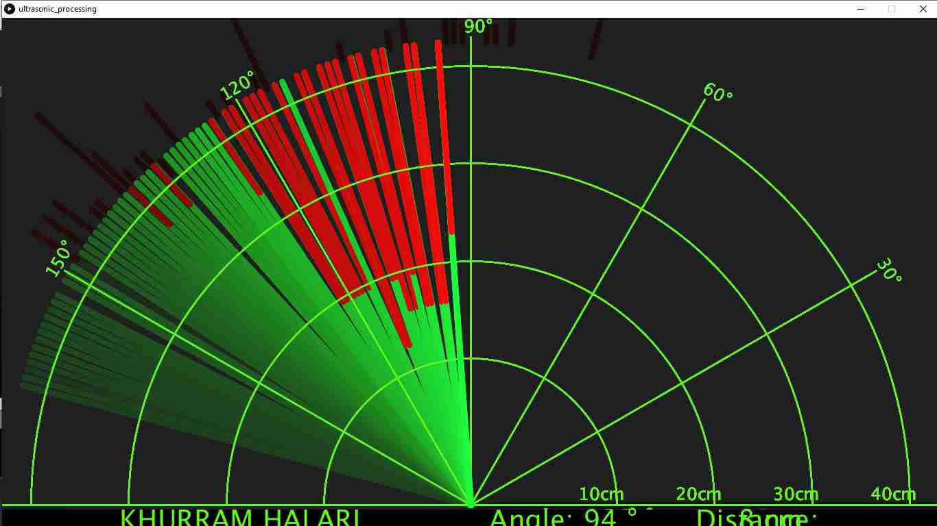
The object is detected by the sensor.
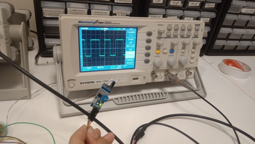
Tasks: Group assignment
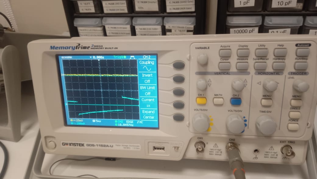
I start by calibrating the oscilloscope, and the steps are described below.
1.Examine all the controls on your scope and set them to
2.Turn your oscilloscope on. ...
3.Set the VOLTS/DIV control to 1. ...
4.Set the TIME/DIV control to 1 ms. ...
5.Set the Trigger switch to Auto. ...
6.Connect a probe to the input connector. ...
7.Touch the end of the probe to the scope's calibration terminal.
Touch the end of the probe to the scope's calibration terminal.
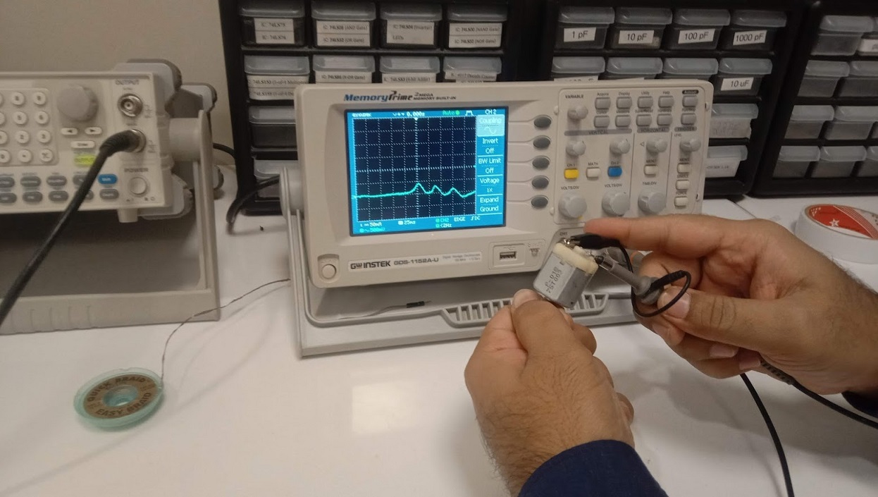
Then I connected the infrared sensor to the oscilloscope to get the signal.
"Click here"to download all files of this week