Week 7
Another fun and creative week has come, and everyone is is ready to be a carpenter, well a computer controlled carpenter because in this week's assignment we will be fabricating something big using CNC machines such shop pot and big milling machines.
1. Group assignment:
do your lab's safety training
test runout, alignment, speeds, feeds, materials, and toolpaths for your machine
2.Individual assignment:
make (design+mill+assemble) something big (~meter-scale)
Learning outcomes
- Demonstrate 2D design development for CNC production
- Describe workflows for CNC production
Group assignment:
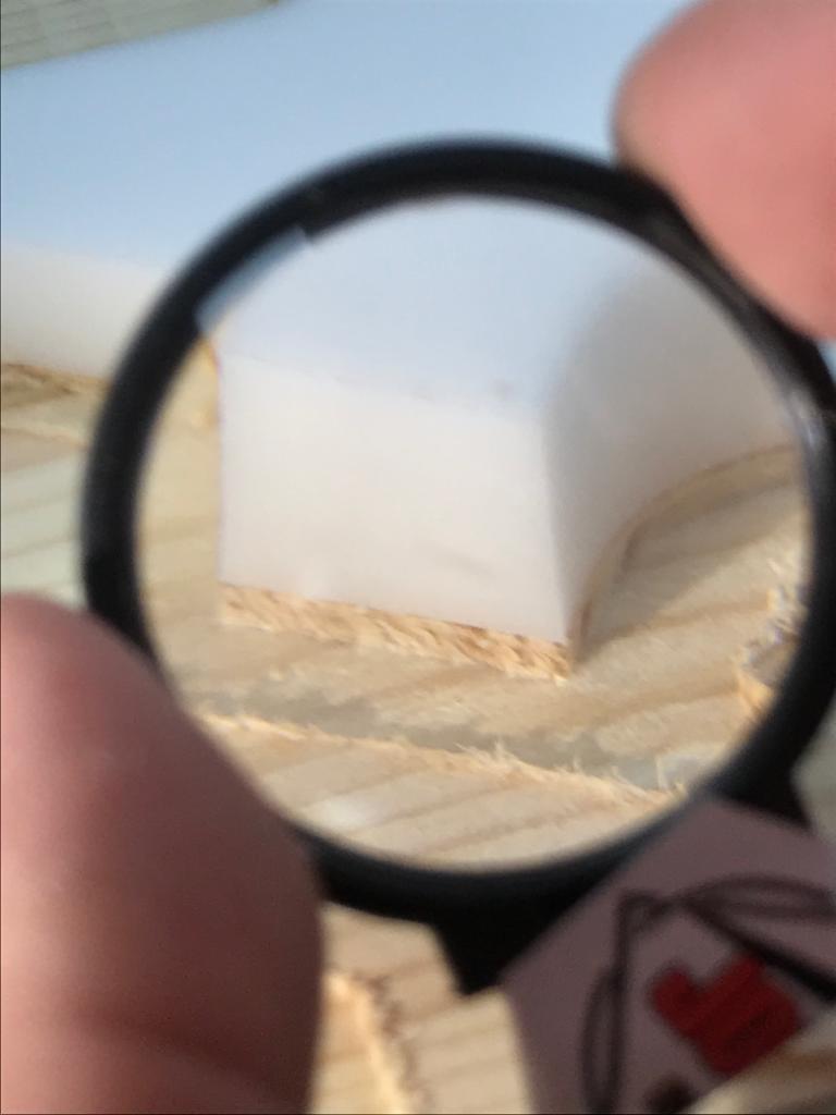
So, for this week we did a fit test to characterize the machine run out and kerf so then we can come up with a design that is a perfect fit with no issues. Thanks to my college cicely she designed this nice-looking press fit model that we can use for testing the machine.
Spindle speed and federate:
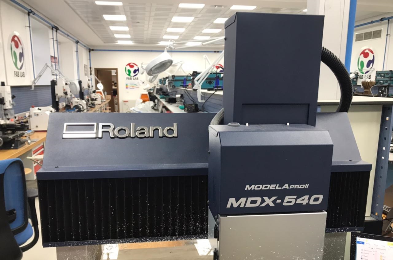
The feed rate is the rate at which we move the mill bit across the material. The Spindle speed is basically determined by how fast the spindle turns the cutting tool. Depending on the material being cut, the feed rate and spindle speed will change. A typical rule of thumb is to pass the tool through the material as fast as possible without ruining the surface finish so basically we have to find out what would be the best spindle speed and federate in order to have a nice surface finish and of course without breaking the tool.we will be using roland MDX-540 as our CNC machine since our lab still do not have the big shopbot machine.
We did 3 samples with 3 different settings:
| Spindle Speed(rpm) | Feed Rate(mm/min) | Material Thickness | Tool Diameter | |
| sample 1 | 12000 | 1800 | 12.1 | 6mm |
| sample 2 | 12000 | 1000 | 12.1 | 6mm |
| sample 3 | 12000 | 800 | 12.1 | 6mm |
First sample:
The first sample is usually a failure in any kind of test so the moment the machine started cutting we noticed that federate speed is just too fast just by the sound of it so the job was not that accurate because in the last layer It started cutting through the tabs created to stabilize the object from moving however the surface finish was not so bad so we know that the spindle speed is good enough we just have to play with feed Rate to get the best result.
second sample:
we decreased the the feedrate 1200 to see if it makes any difference and it did improve the surface finish but it was a bit fast it cut the tabs that was created to stop the object from moving so that means we have to decreas the speed even more.
Third sample:
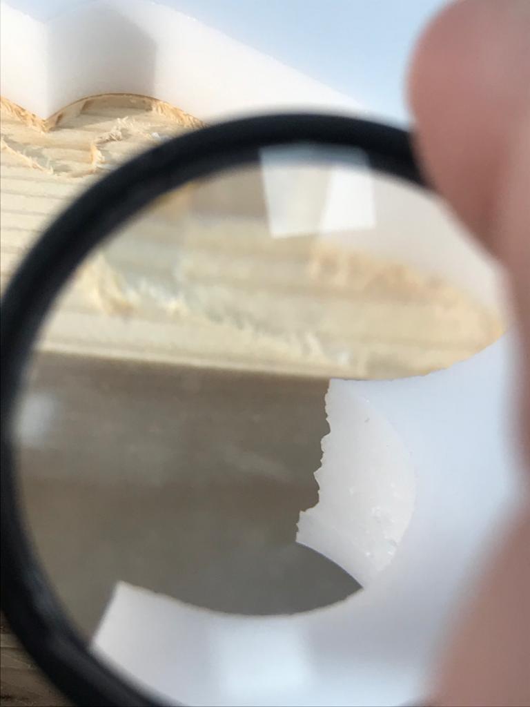
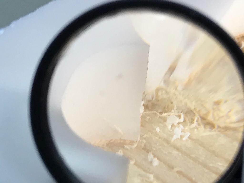
in third sample we decreased to 800 and the surface finish imporved drastically as showen in the picture so in the future we will be using these settings when cutting a 12 mm plastic sheets.
CAD Designs :
Unfortunately, we still don't have the shop pot machine so we cant really create something big so we decided to make a design for it now and then when the machine arrives we can do it.
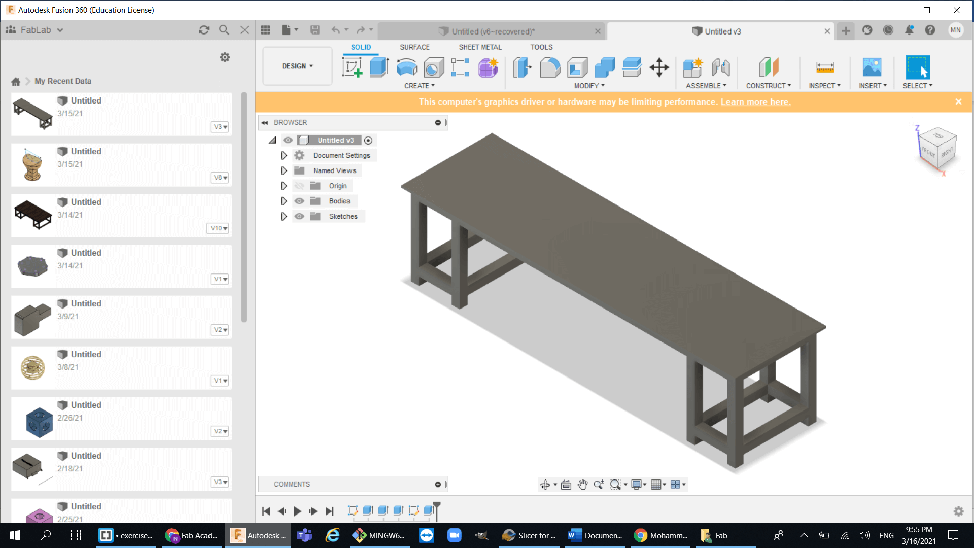
So for now I started doing some designs on fusion360 and I came up with this desk design:
After I made the desk design, I saw my collage designing an egg-shaped chair so I wanted to do the same but a table instead of a chair.
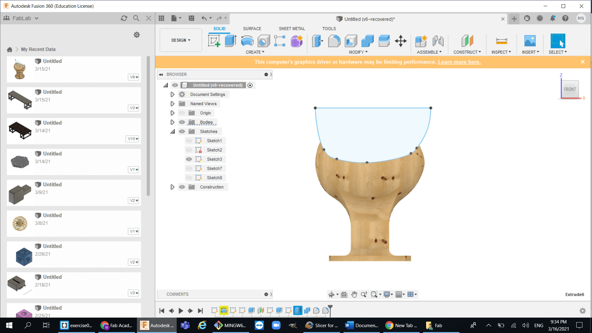
Here's how I did my egg-shaped table::
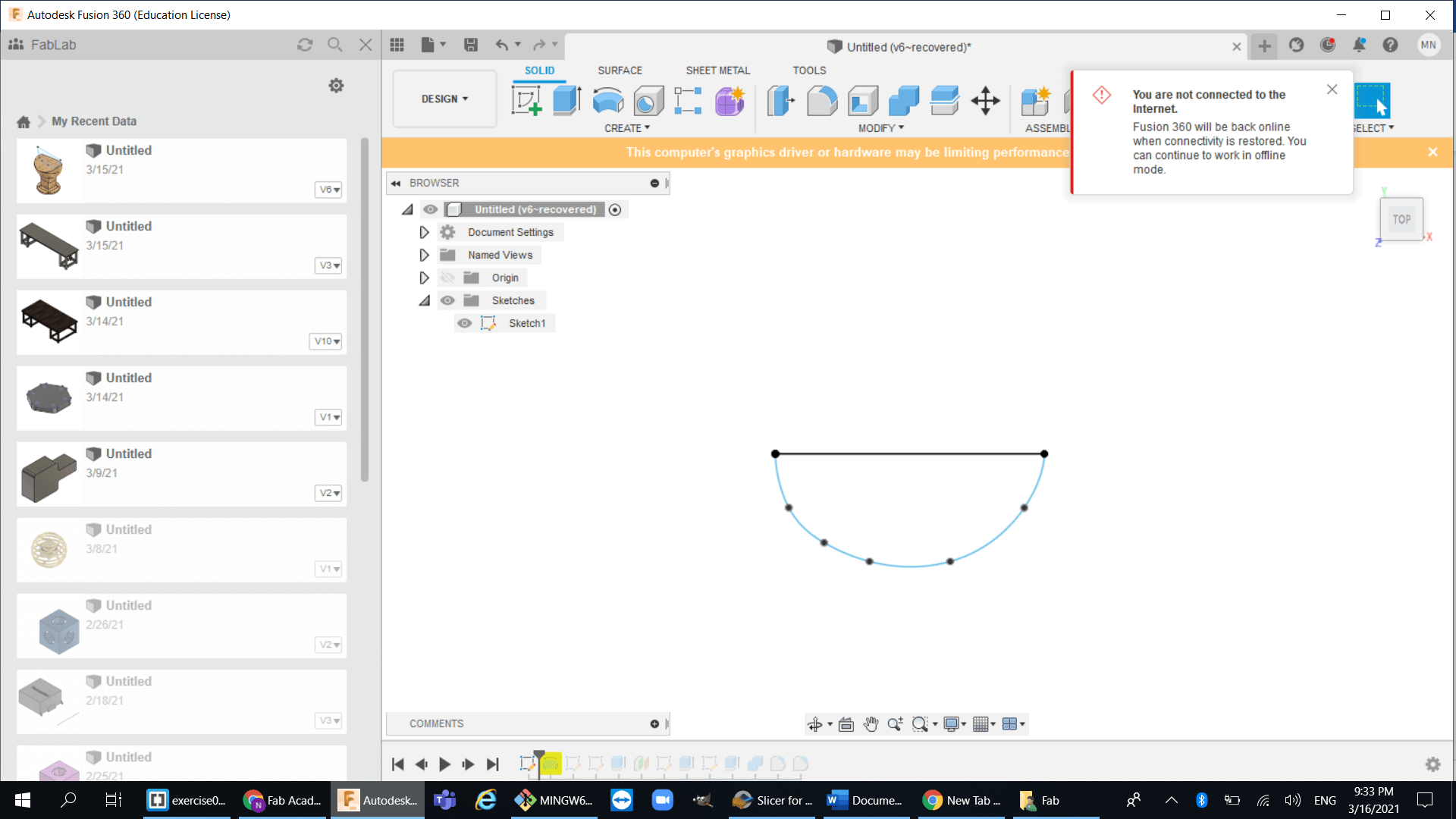
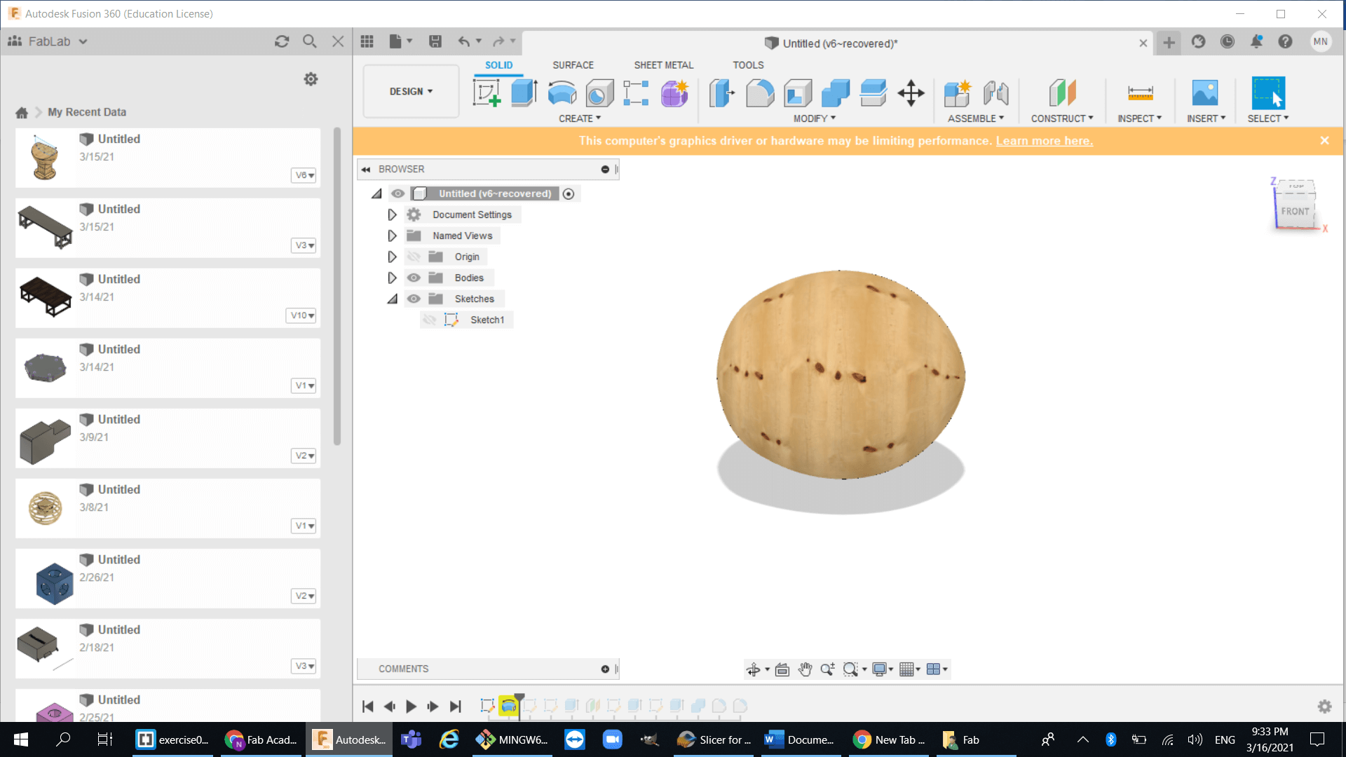
1.Create a simple polygon then revolve around horizontal axis to make an egg :
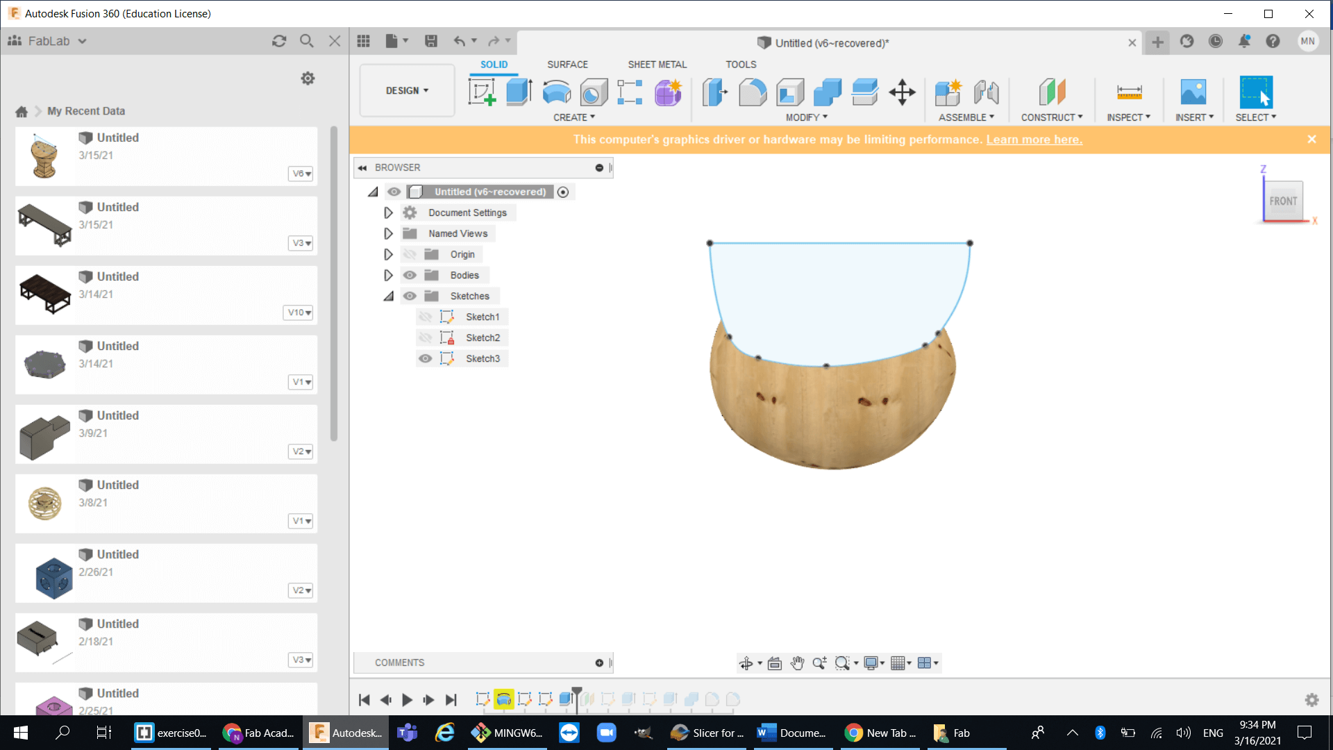
2.Then cut through it with another polygon
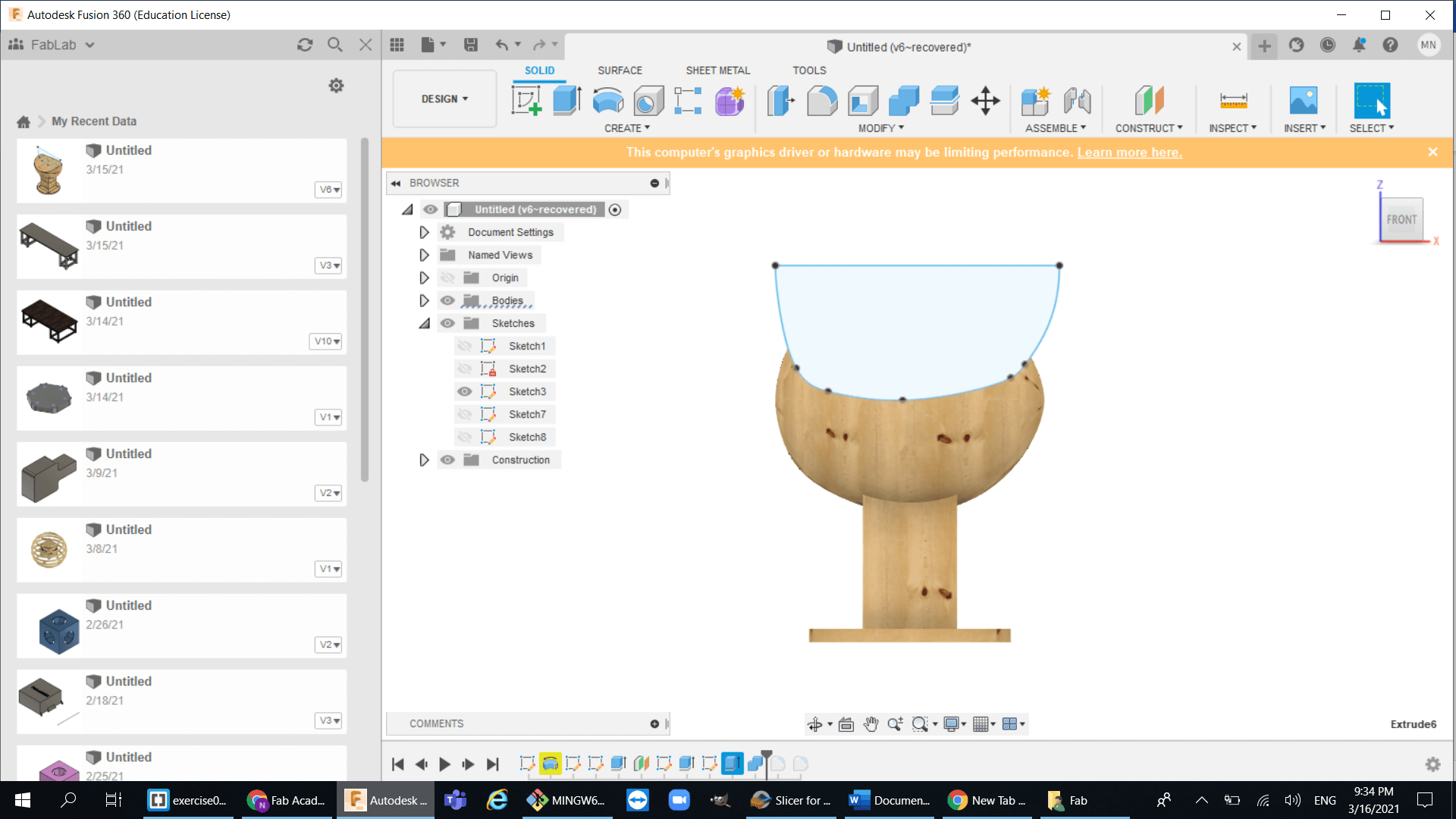
3.Now create the base for the table :
4.Finally use the fillet tool to make stronger and look better :
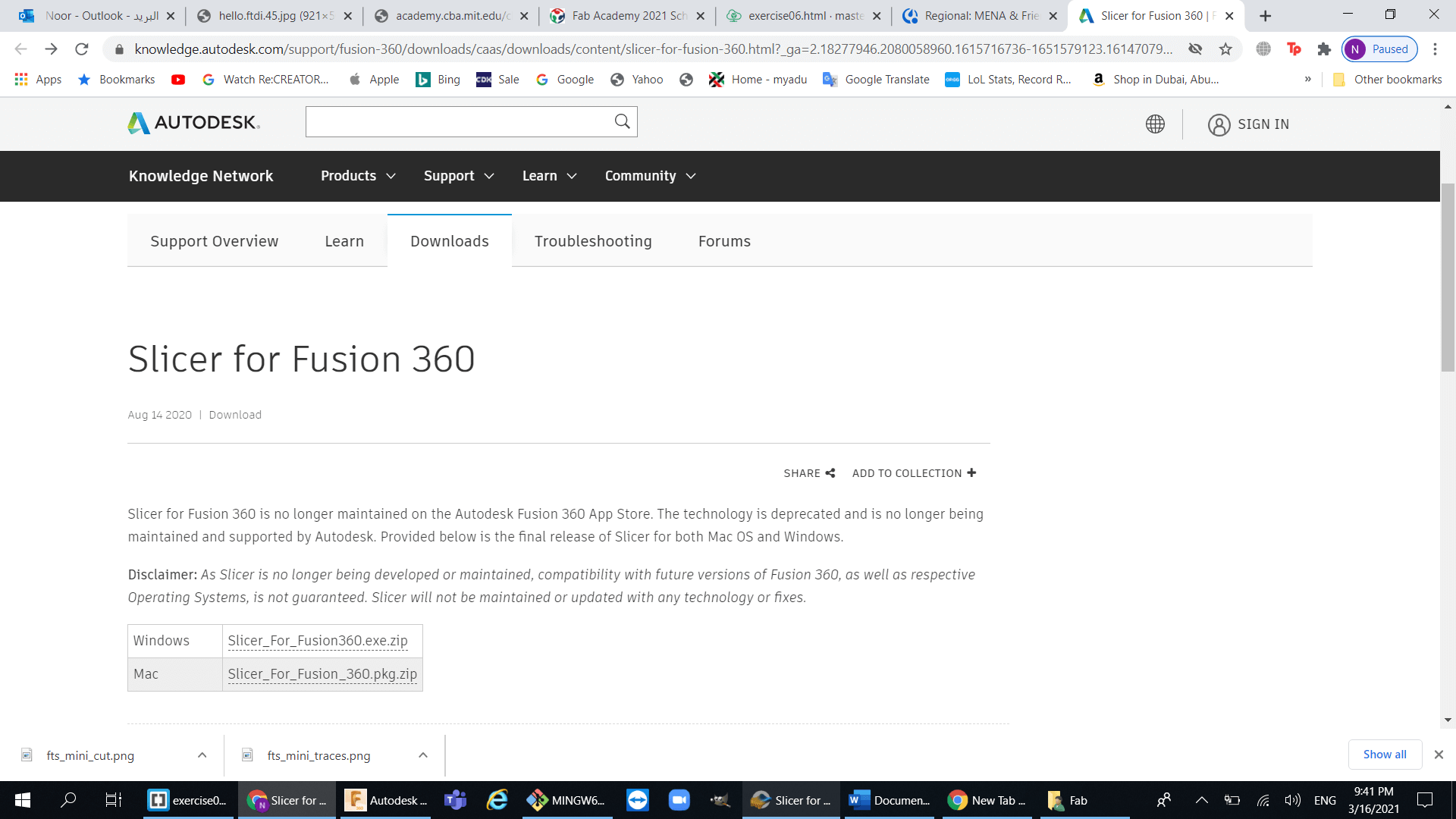
Slicer:
After I was done with the design, I used a program called Slicer, and this probably one of the best programs that I will be using a lot in FabAcademy. I highly recommend using this program.
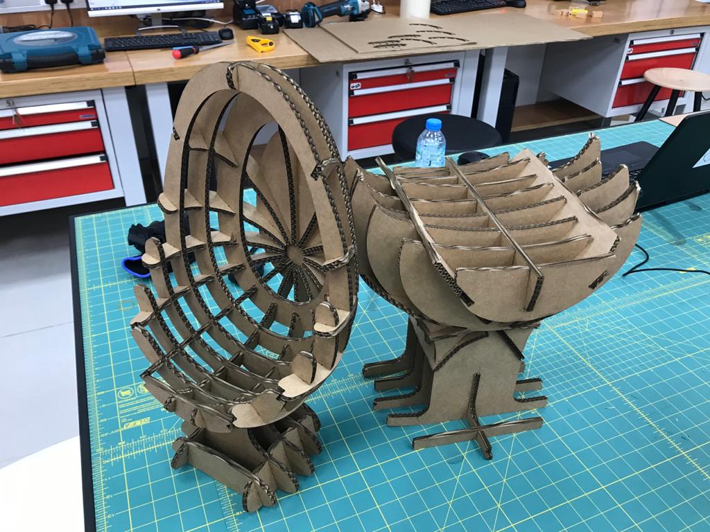
So basically, this software converts your 3d model into bunch of 2d segments and then you can assemble those segments to create your 3d object:
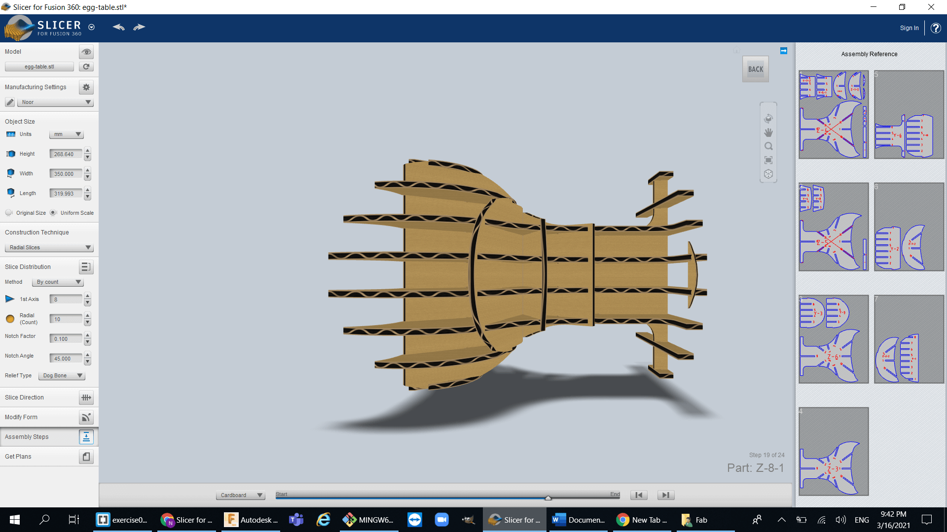
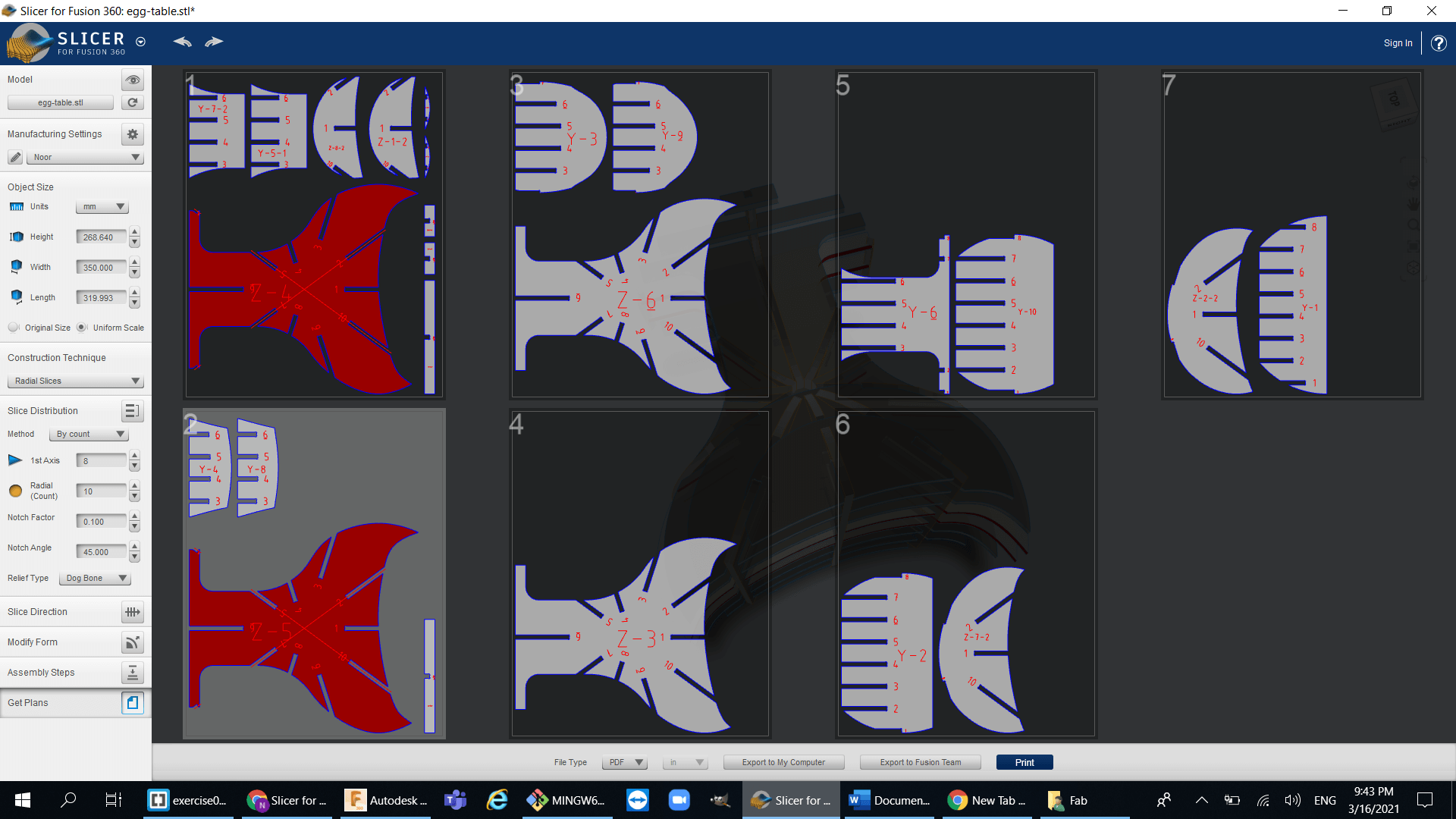
so using slicer I was able to export my table design and then make it into segments :
Cutting and assembling the Table:
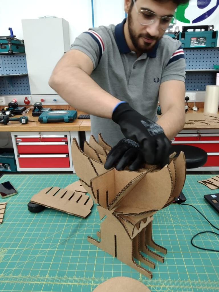
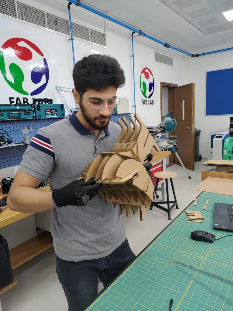
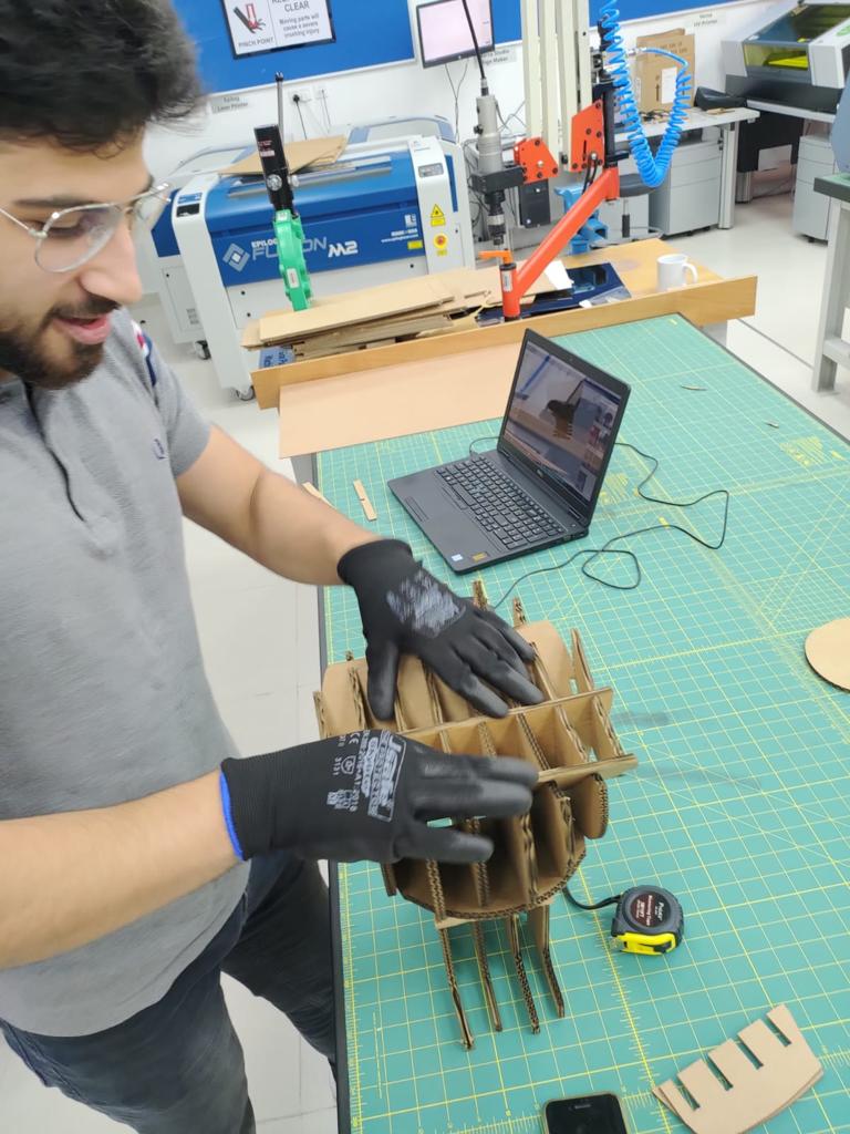
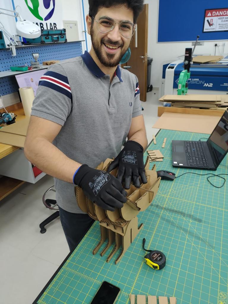
Different Design:
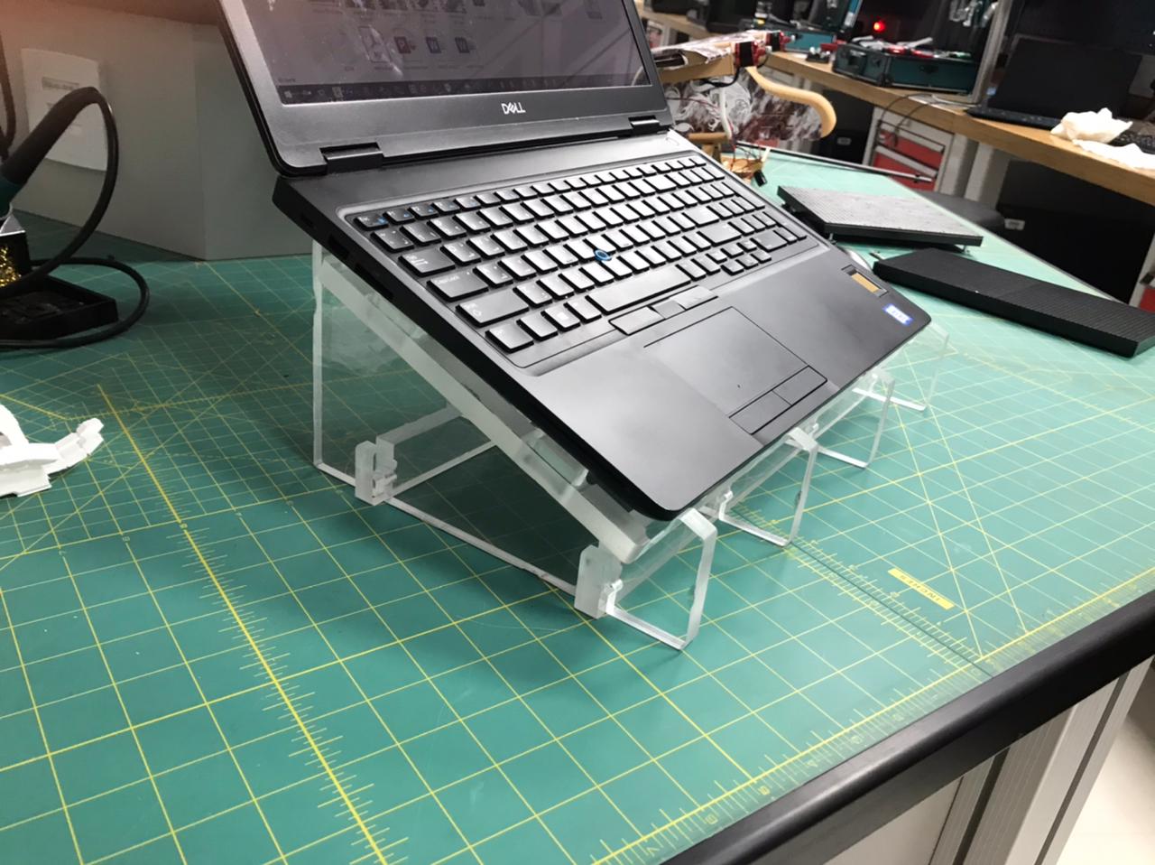
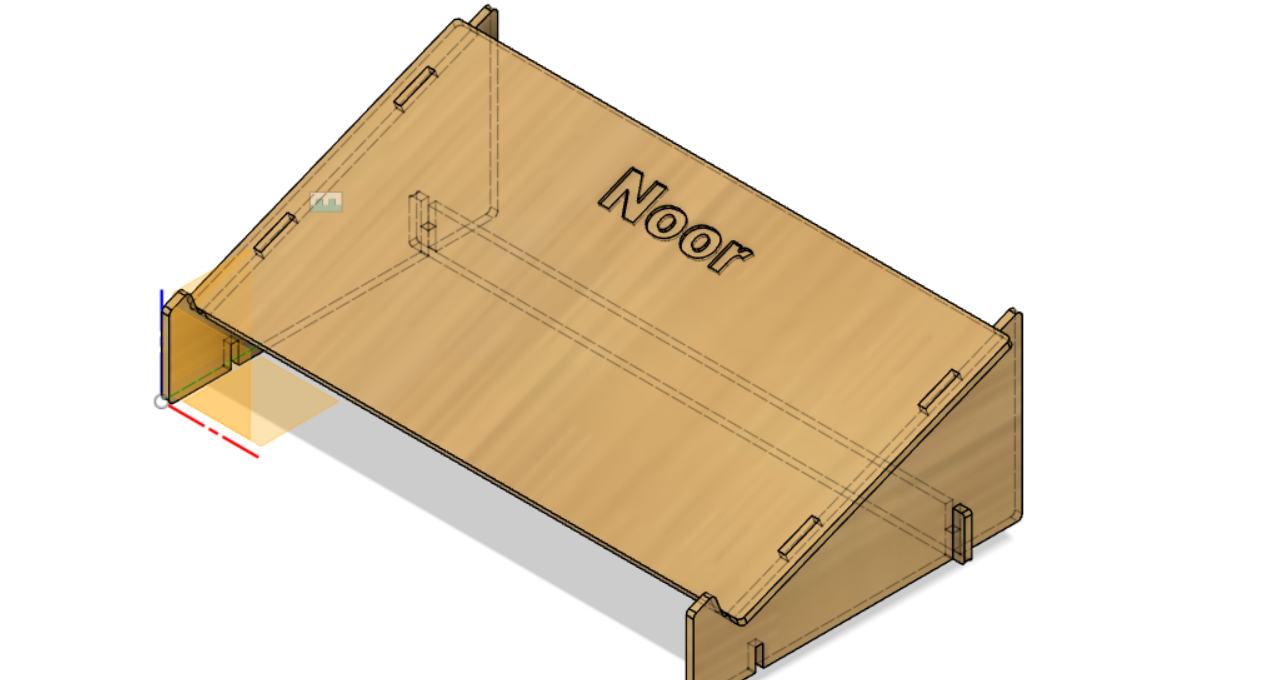
Due to time limitation I couldnt actually use the CNC machine to cut the table that I made using the laser cutter so I decided to take my old laptop stand model from week3 and modified to fit the CNC machine requirements.
Preparing the Design:
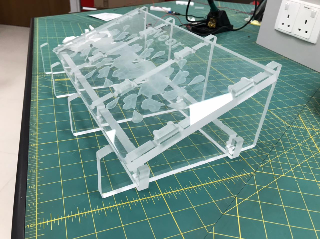
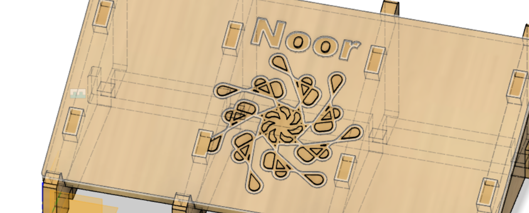
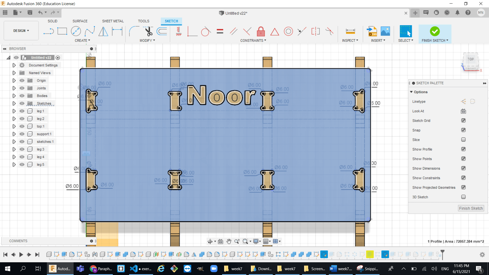
- So first I did some art work on the top surface to make look better.
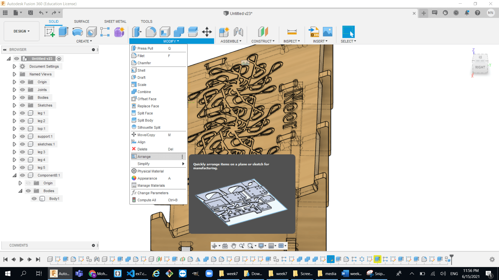
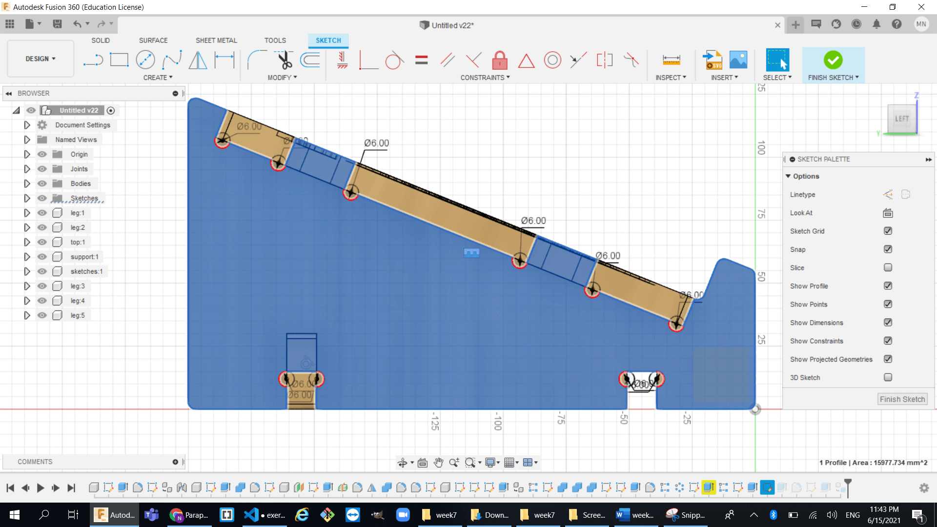
- then I convert all the finger joints into T-bone joints because it will give more tight fitting parts and so much better than just finger joints.
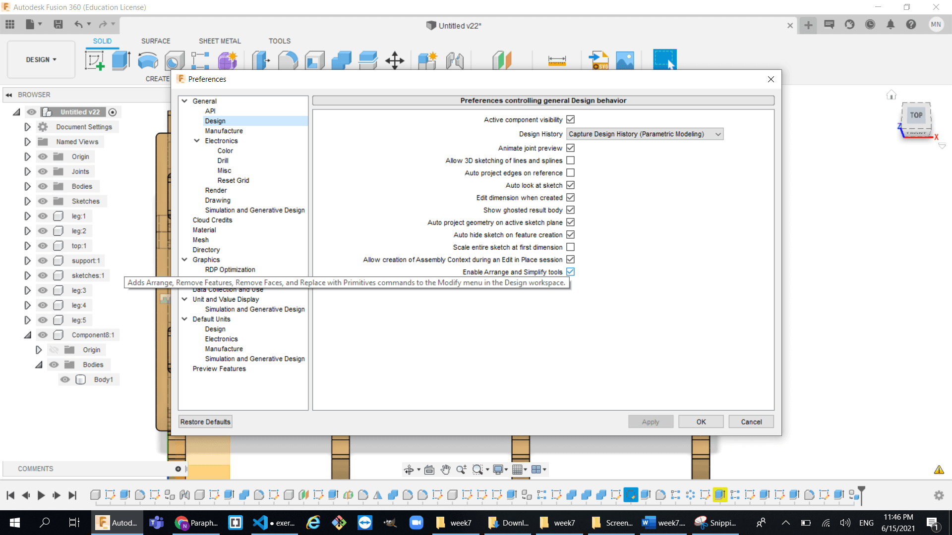
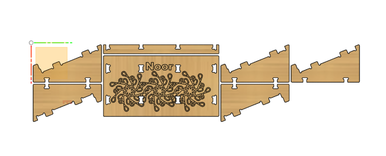
- Finally I used the arrange tool to prepare the parts for CAM and to do that:
- enable the arrange and simply tools library in the prefrences
- then use the arrange tool to arrange each part of the model to one plane.
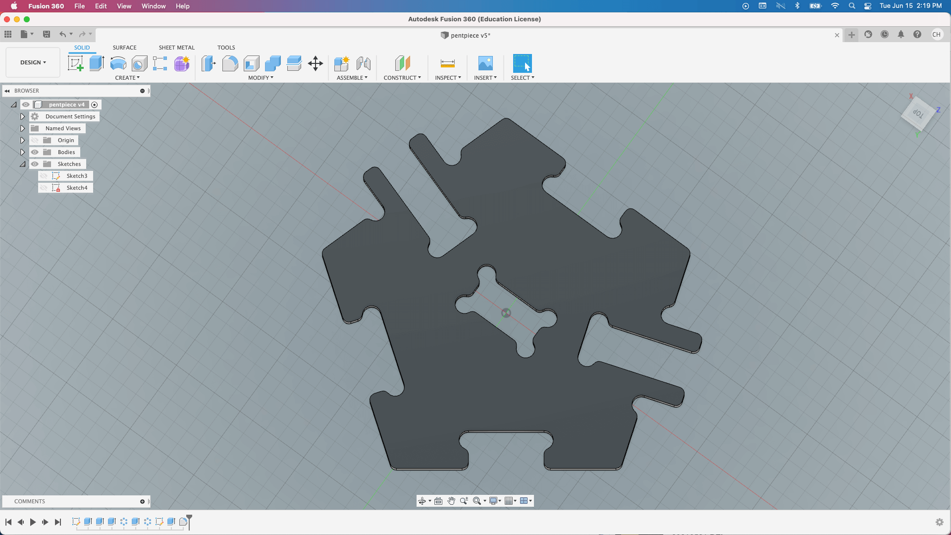
- this is how the design look like after using the arrange tool:
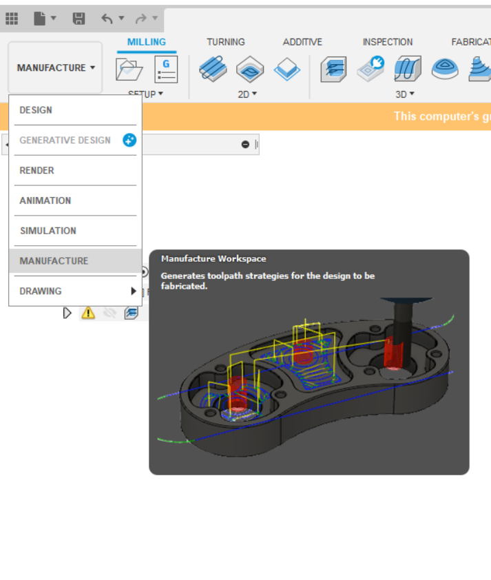
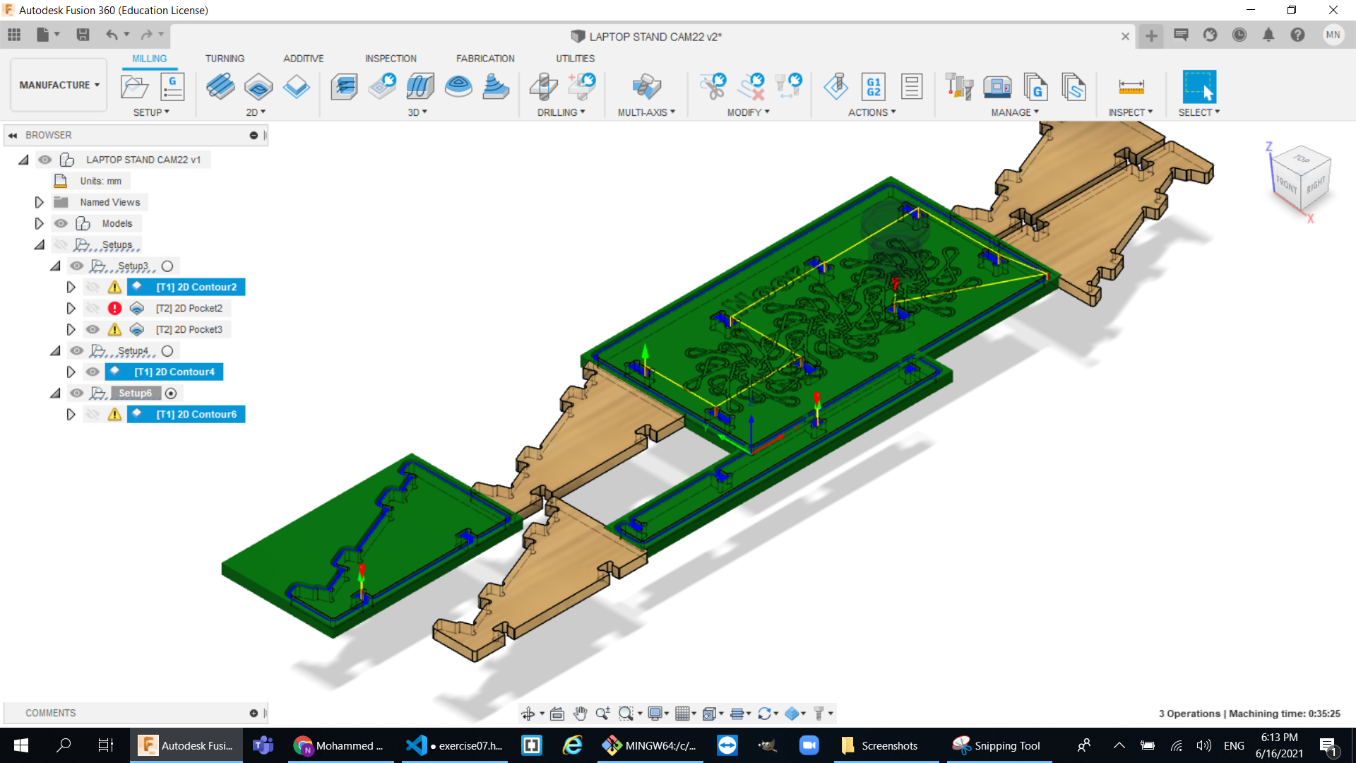
CAM Design:
Cam design is basically telling the machine how to operate like choosing the tool and the tool path. So first go to the manufacturing tab in fusion:
- cutting using the 6mm Tool:
- create a setup and select the machine that is going to be use
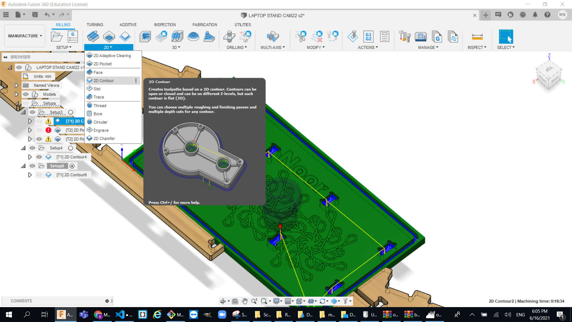
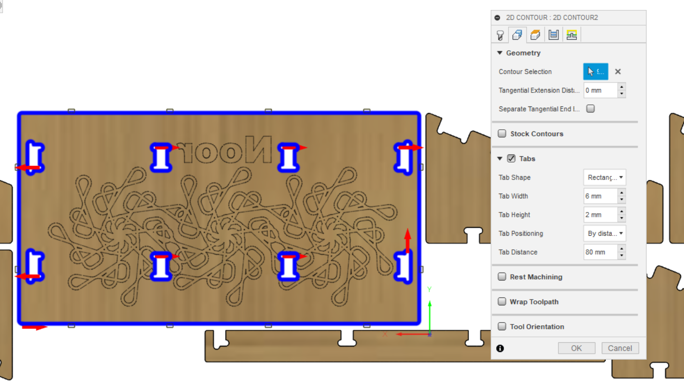
- I used the 2d contour tool path to cut through my object
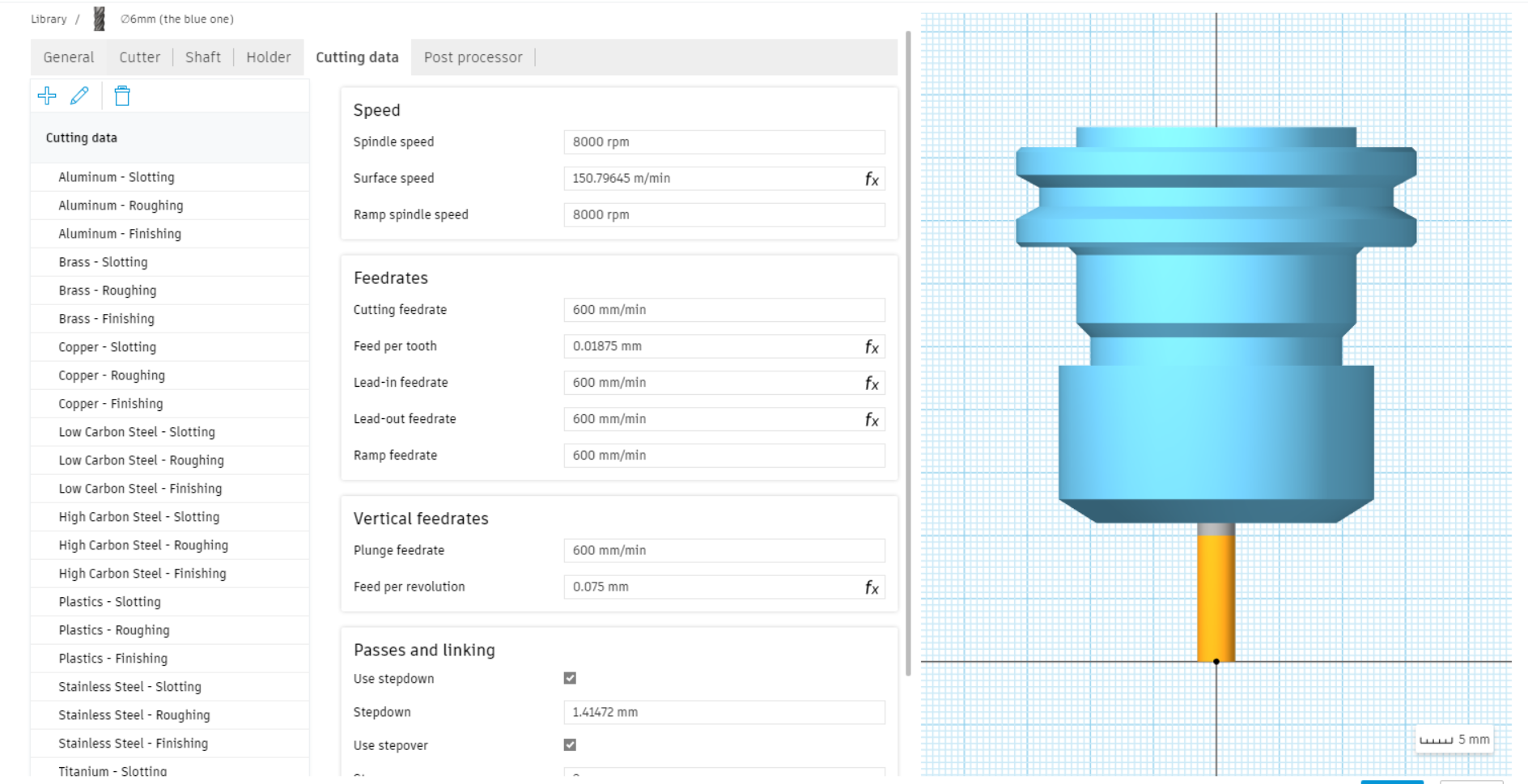
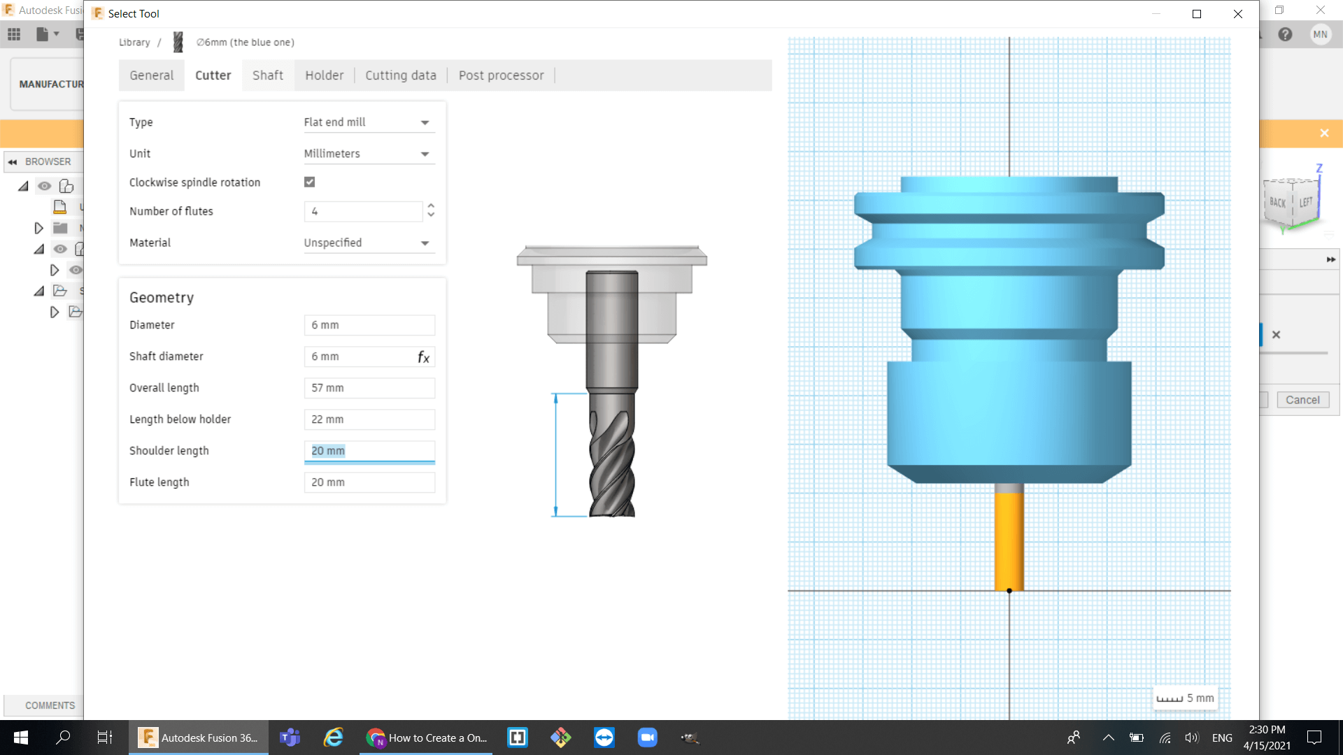
- select the tool and adjust the setting to fit your tool. Mine was 6mm flat mill bit:
- select the face:
- I used the same method to do all the legs and supports :
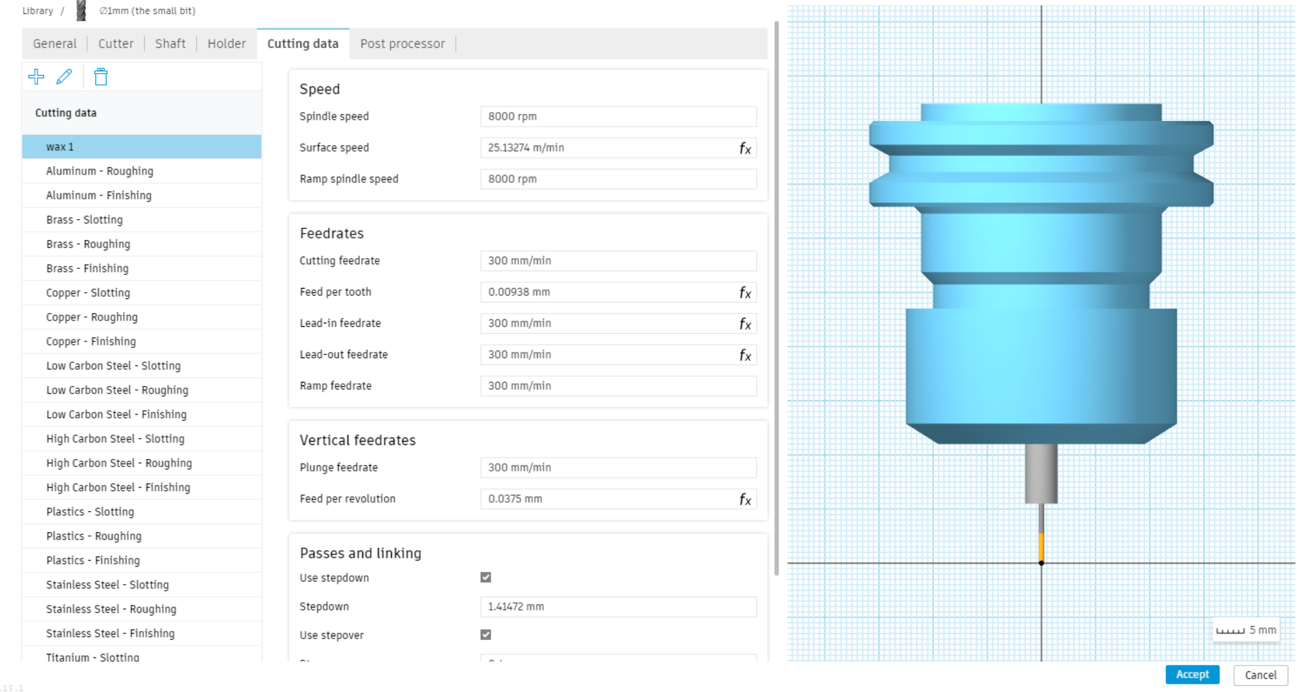
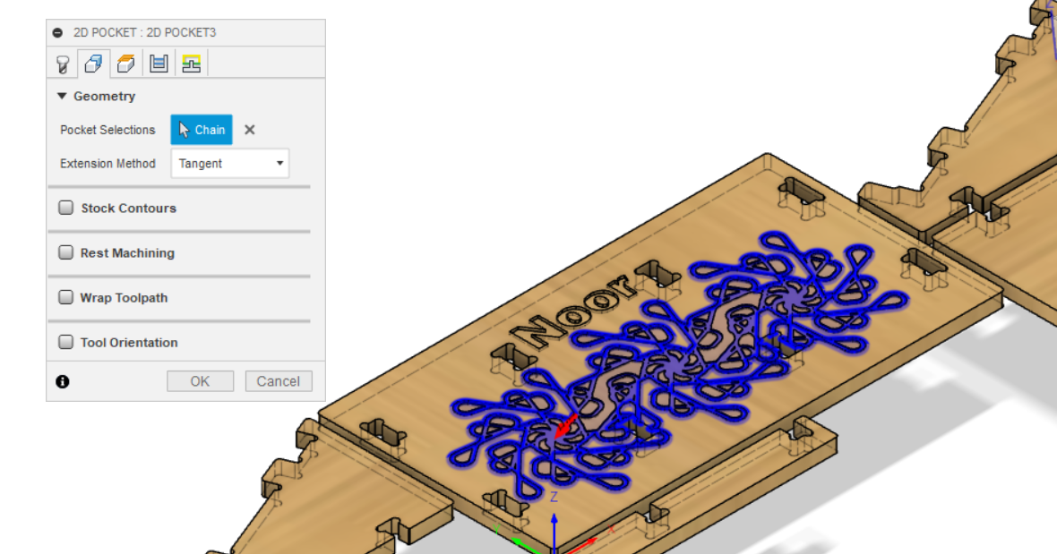
- engraving using the 2mm tool
- select and adjust the settings for the 2mm mill bit:
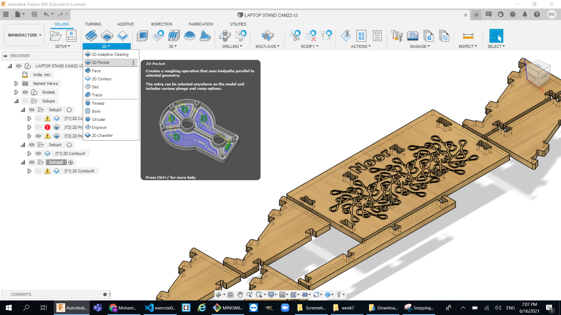
- now to engrave the shape that I have I created a 2d pocket clearing tool:
- select the face :
- Job Simulation:

The milling process
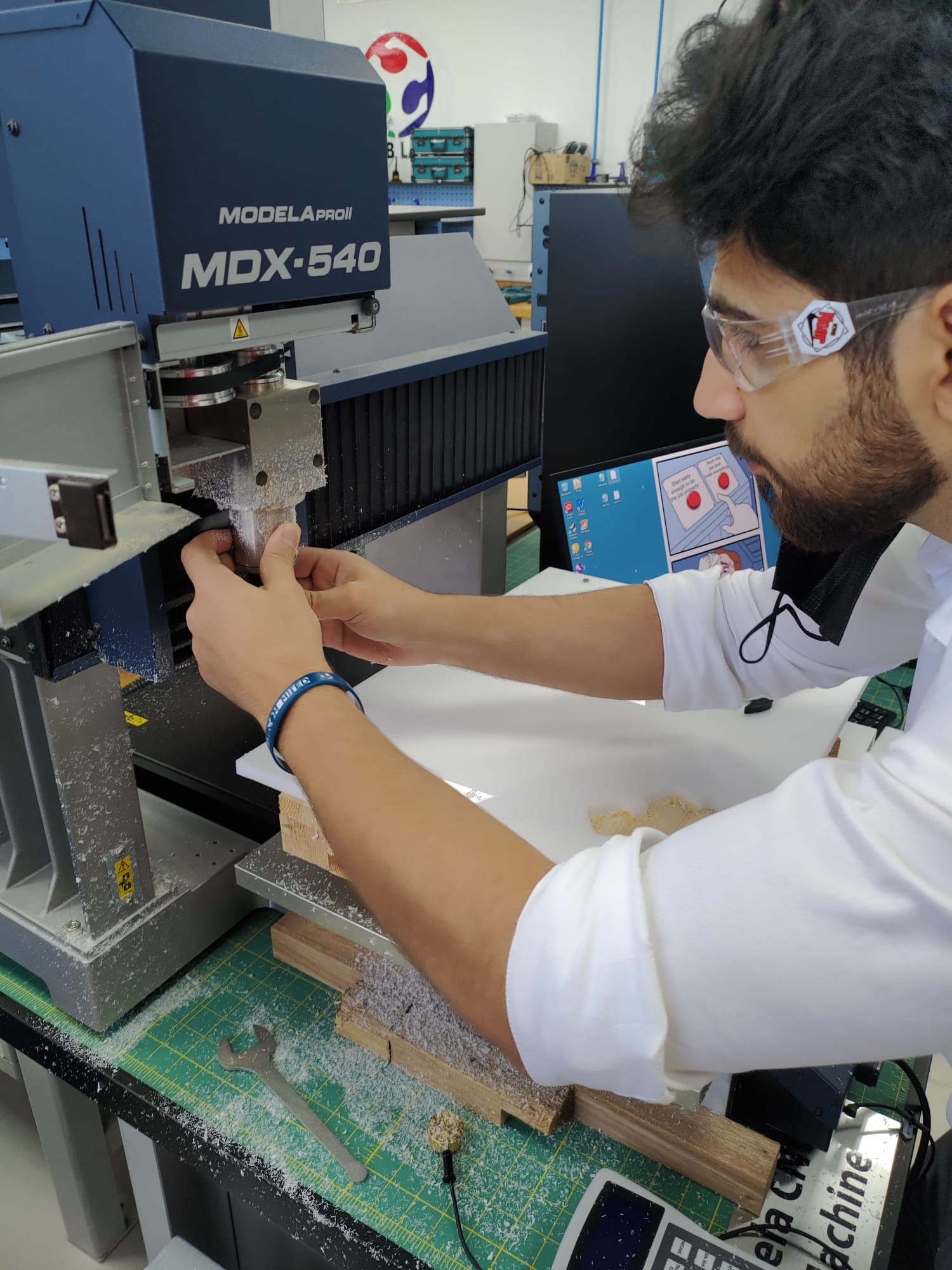
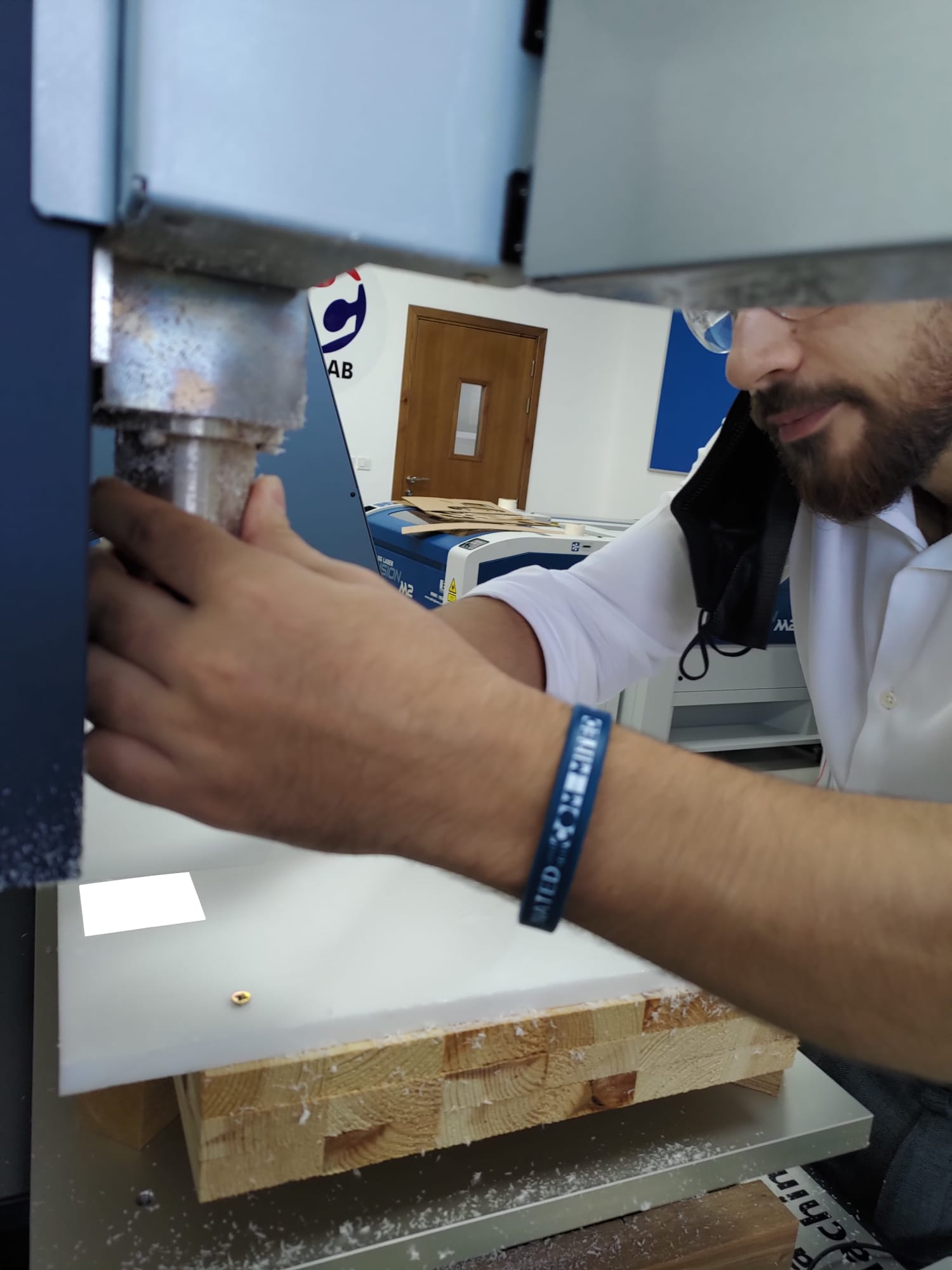
so after exporting our G-Code from fusion the rest of the job is done by the machine and you just watch it doing the job but before we start cutting we need to prepare the machine.
Steps to prepare the machine:
- First of all make sure to apply all the safery precautions.
- Make sure that the sheet is fully stable before cutting anything(we used to bolts).
- Put the proper tool for the job.
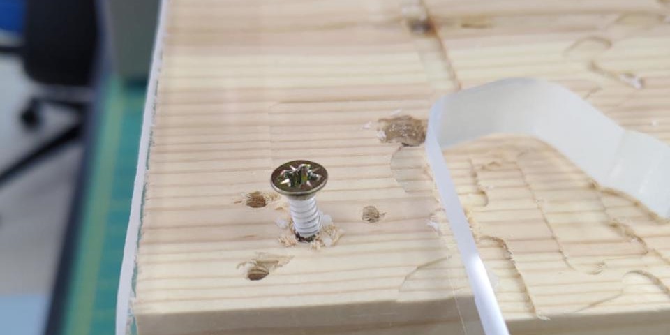
- Zero the x ,y then do an air cut test so you roughly know that your job will be in the right place because it is very dangerous if the tool hit any of the screws.
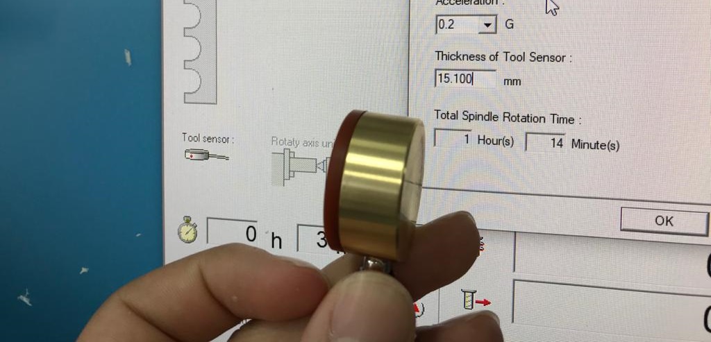
- Finally use the sensor tool to zero the z and then start cutting
- Video of milling:
- Final Results :