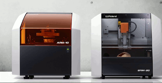
Week 6
I am an absolute beginner when it comes to electronics, so I am super excited to learn a new skill. In this week I am going to learn how to design my own circuit board from scratch and then test it and program it. as for the assignment:
1. Group assignment:
Use the test equipment in your lab to observe the operation of a microcontroller circuit board (in minimum, check operating voltage on the board with multimeter or voltmeter and use oscilloscope to check noise of operating voltage and interpret a data signal)
2.Individual assignment:
Redraw one of the echo hello-world boards or something equivalent, add (at least) a button and LED (with current-limiting resistor) or equivalent input and output, check the design rules, make it, test it.
Learning outcomes
- Select and use software for circuit board design.
- Demonstrate workflows used in circuit board design.
Kicad Design :
Kicad is a great software to work with since I am new to electronics I felt like this a start up program that I should learn and fortunately it was downloaded on my laptop and I chose because it is a free program with open resources.
So I started by downloading the fab library that is posted on the schedule then export it to my kicad as well as the footprint library.
Due to covid restrictions our lab inventory still did not arrive, so we had to work with the resources that we have. So what we did is learn the milling machine and then created a simple circuit using kicad and since we do not have the components we decided to connect the circuit to the Arduino and program it.
Go to creating a new project then go to the schematic editor, this the circuit I wanted to create and it contains 3 leds with 3 resistors :
.jpeg)
After creating the schematic design we generate a netlist so we can update to the pcb design :
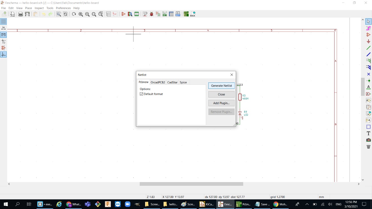
Then start working on pcb design and try to connect all the components with traces , then make an outline for the circuit using edge cuts color :
.jpeg)
.jpeg)
and before we export the file to svg , check the design rules and make sure that clearance fits our design:
.jpeg)
finally export the svg file as followed :
.jpeg)
I personally used gimp to take out the traces and the outline separately, but any software can be used:
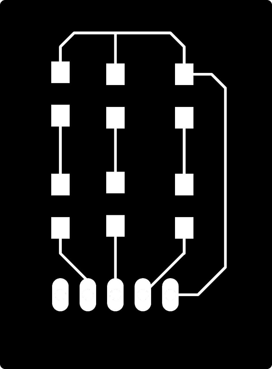
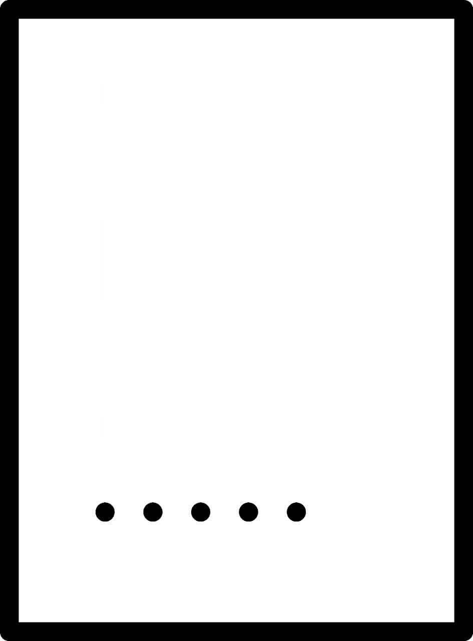
Milling and soldering the board:
So we have a roland spm milling machine in our lab:
we used two kind of v-bits:
1.1/64: for cutting out the traces
2.1/32: for cutting the outline:
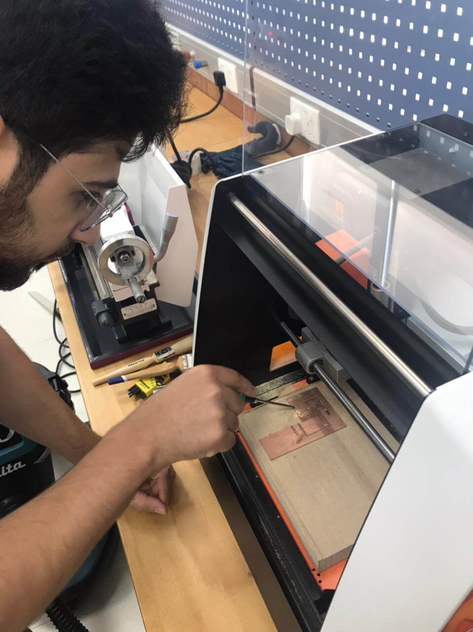
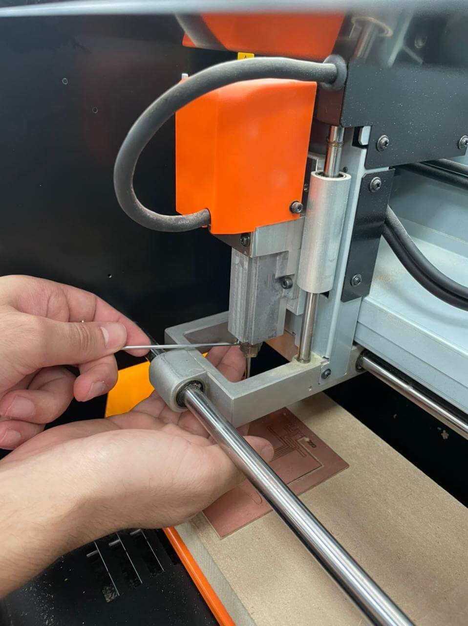
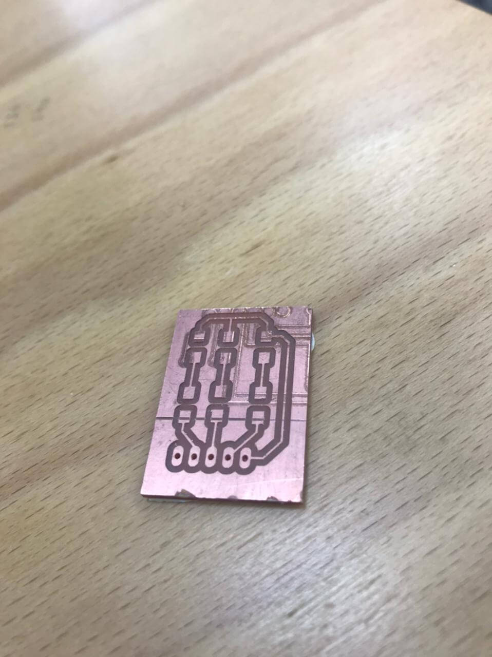
After cutting out the board it is time to start soldering the components:
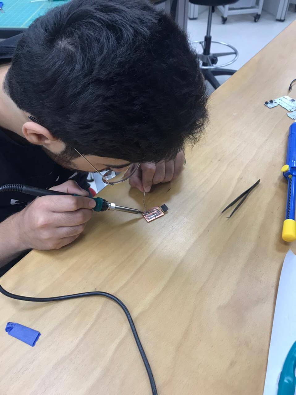
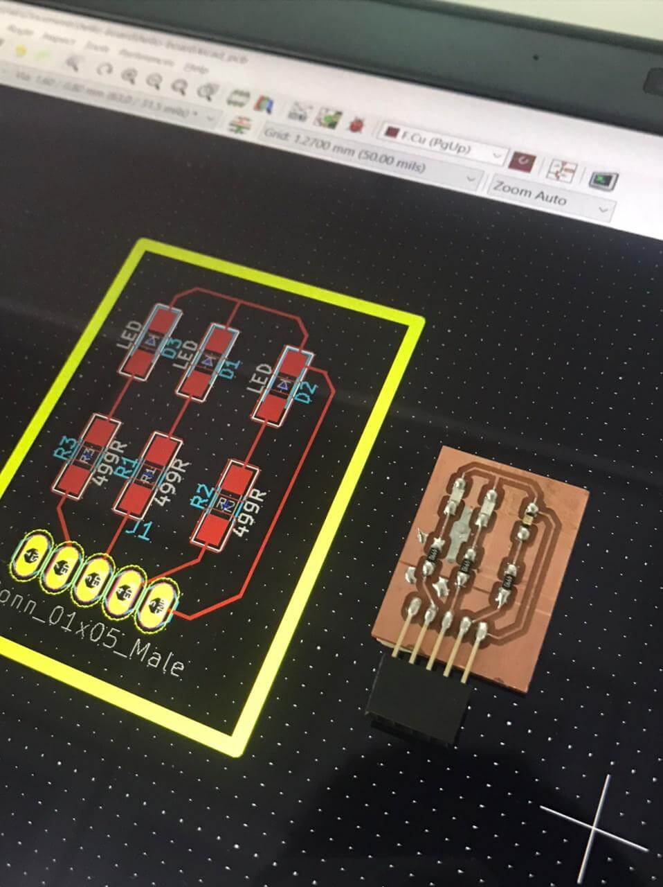
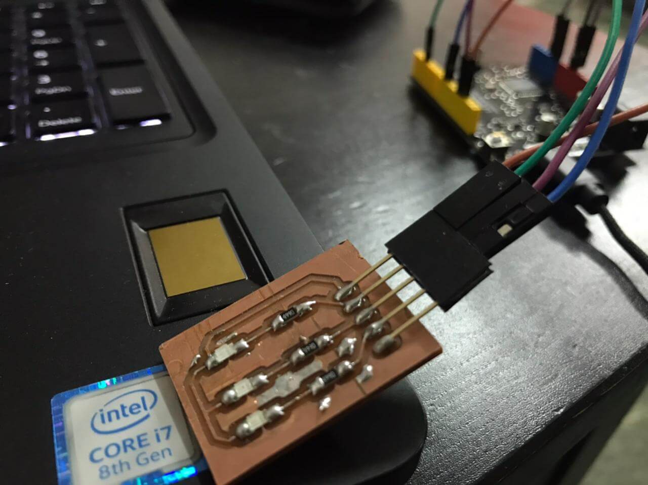
Now the circuit is ready to be connected to the Arduino so we can program it
Testing and programming:
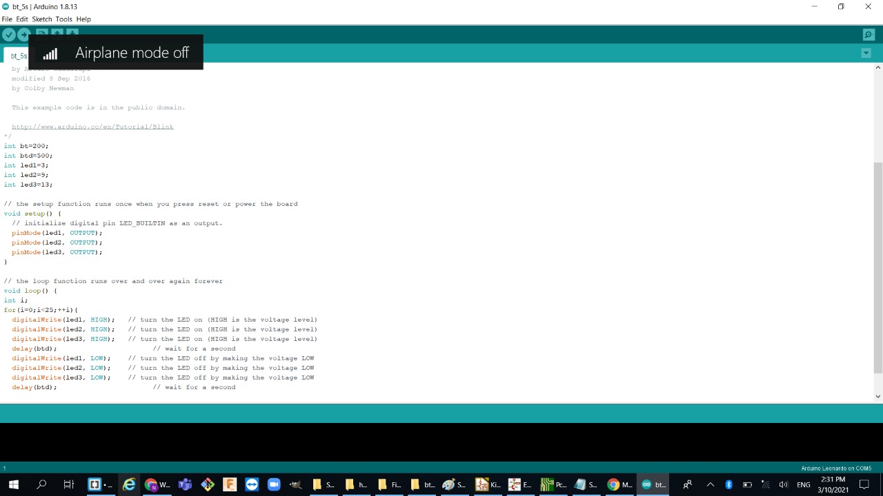
Since we still do not have our lab inventory we connected the circuit to the Arduino and programmed a simple blinking leds:
hello-board design :
Finally, after waiting for two weeks some components has arrived so now I can start fabricating my hello-board circuit:
For this week assignment we had to redraw one of Neil's echo hello-boards and then add led and a button so this the board that I will try to redraw:
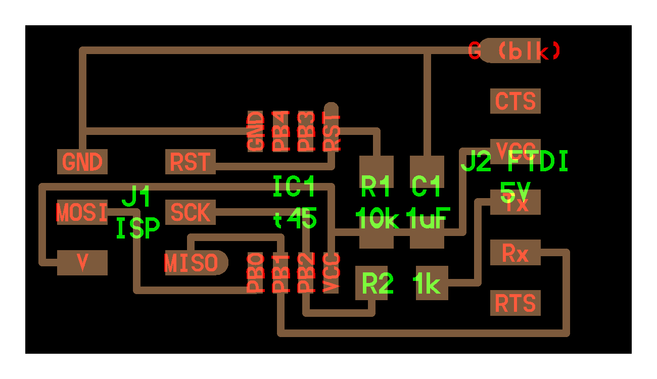
Hello-board kicad design :
4 simple steps To redraw neil's hello-board :- Open the schematic then start adding your components + adding LED and a button:
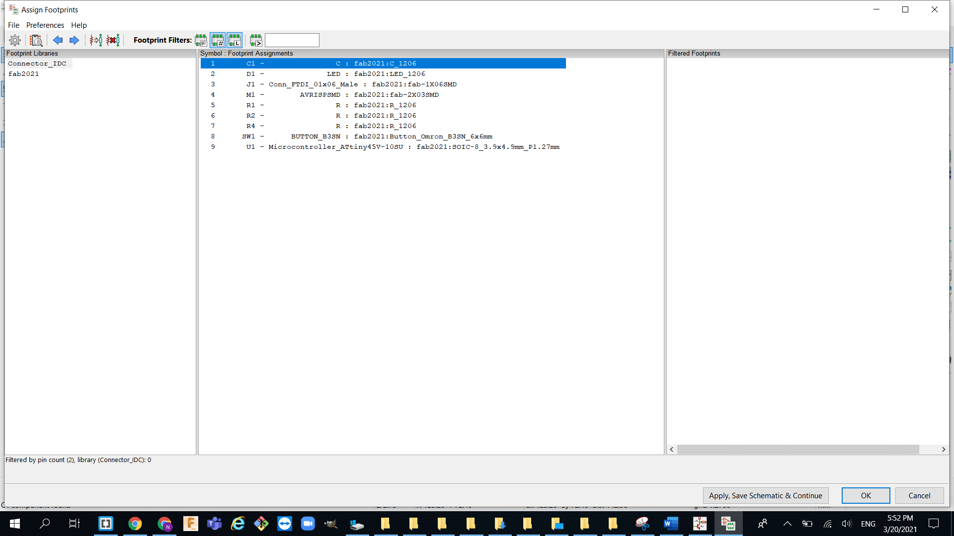
- Assign the footprint for each component:
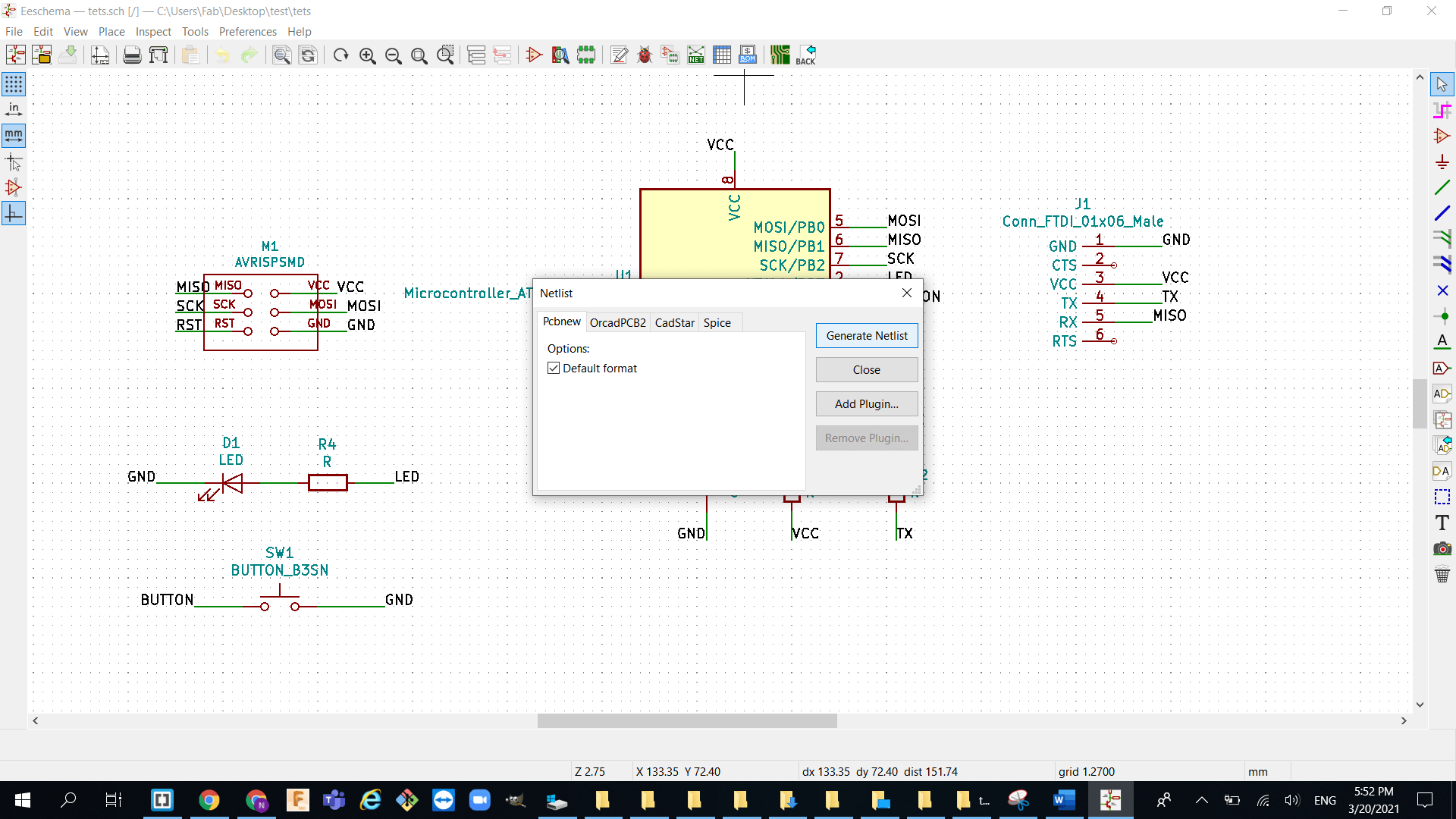
- Generate a netlist and import it to the PCB design:
- Now start wiring everything up with traces :


Milling:
- after exporting my files from Kicad I used gimp to seprate the traces from the outline so I can excute each one alone :
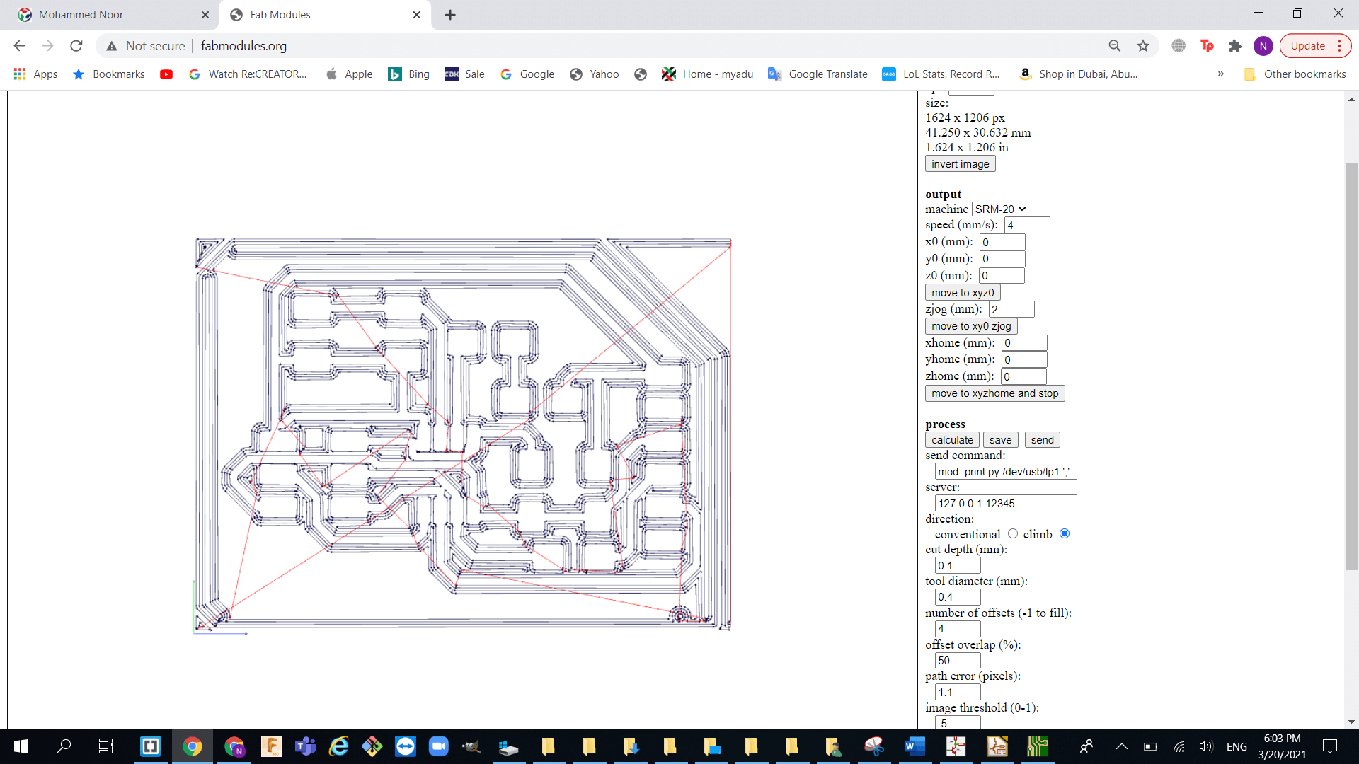
- Now export the PNG files into FabMedoule and follow the same steps in week 4:
- milling process:


Mistake : my mistake was that I did not fill the white corner with black color therefore, the milling machine milled the edges twice and ended up with useless overcut so I will be fixing this problem in my next board which is in week 10.
Stuffing the board:
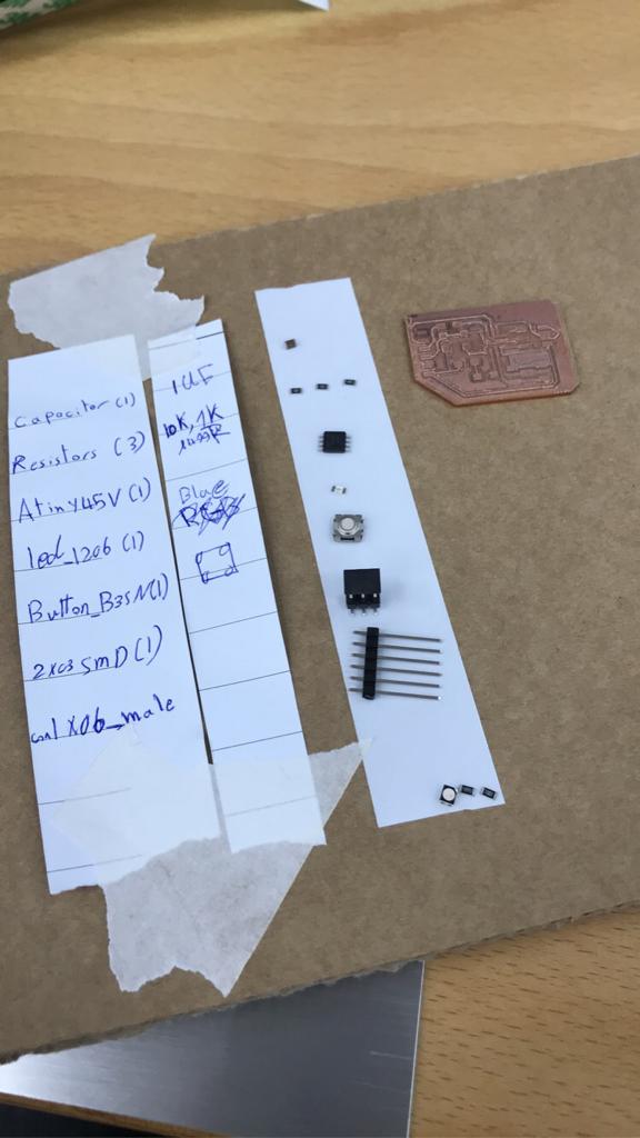
finally i am starting to understand how soldering works after I burned my self with the iron lol , and I learned that it is always best to set your stuff before you start soldering anyway here are the componets needed for my hello circuit:
6-pin header
ATtiny45
2x03 SMD connector
Capacitor (1uF)
3 Resistor (10k,1k,499R)
Button
LED

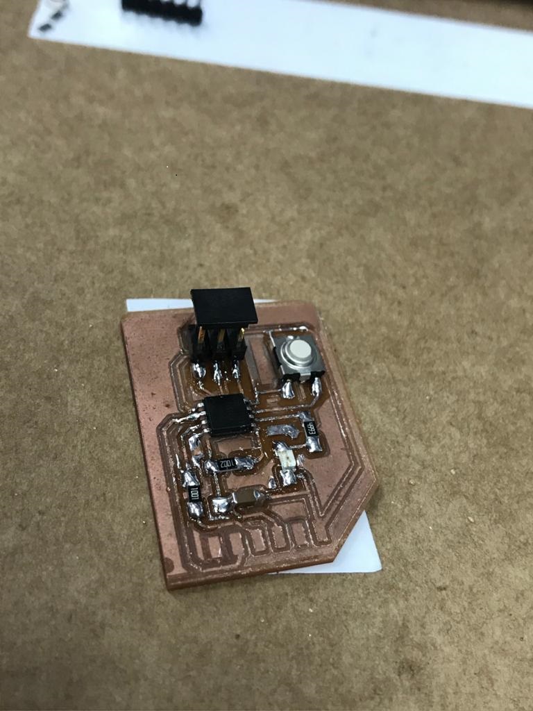
Testing the board :
- Checking if my board is sending signal through the serial monitor (basically just sending 1 when the button is pressed):
- Testing the led toggle switch
Things I have learned this week:
- Designing pcb using Kicad: at first it was very difficult what was going on but then after some explaintion and practice I was able to understand the process for designing pcbs and that includes dealing and arranging the schematic as well as knowing how to connect the traces in the software.
- Using the milling machine: I was able to learn how to deal with such machines like the Roland SRM-20 and by dealing I mean setting up the computer for it and knowing which tool to use without breaking it , how to set the origin .
- Basic electronics knowledge: knowing what each component does and why do we use it was part of learning how to make the pcb so it can work without any malfunction, and I found this very helpful note from one of my instructors documentation.
- Using the micro-controller: I learned how to assign the micro-controller pins and what each pin is responsible for.
- Adding led to the pcb: first I learned that any led needs a resistor attached to it because most led can not handle the voltage that is coming from the source so we use resistors to limit the current that flows through the led otherwise it will burn.
- Adding a button : the only problem I had to placing the button and wiring it because it had 4 pads that needs to be connected but at the end I placed near the micro-controller pin that I assigned for the button and that was It was easier to wire.
