Week 2 : Computer Aided Design
☛ Assignment
☐ 1. model (raster, vector, 2D, 3D, render, animate, simulate, ...) a possible final project, compress your images and videos, and post it on your class page
▸ OBS Studio
I am using OBS Studio to capture my screen.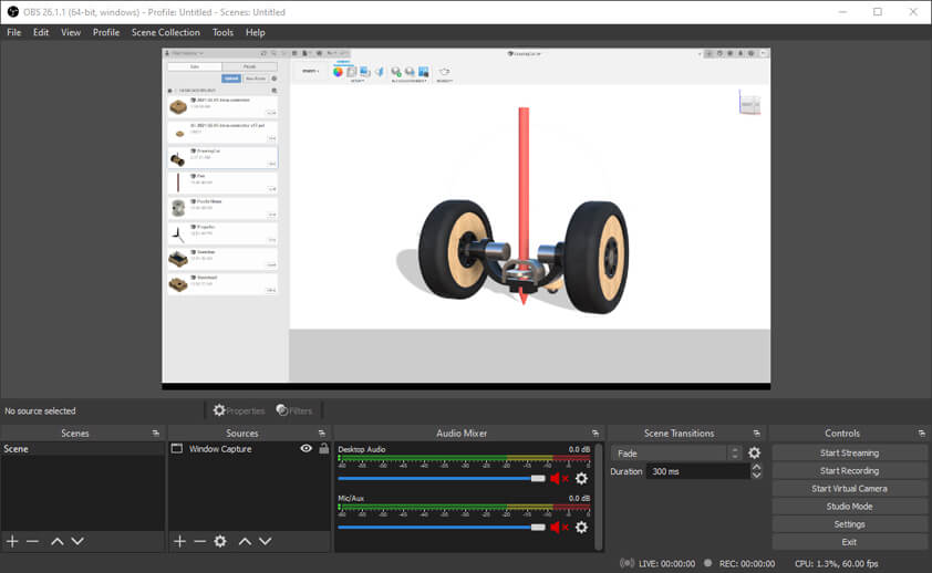
▸ Illustrator
This week I worked on modeling a possible final project. I began by these 2D sketches using Adobe Illustrator but I didn't went very far, I have been using this software for the past 7 years in order to do illustrations and to prepare my files for lasercutting.
▸ Inkscape
I tried once to use Inkscape, and I chose to stay on Illustrator because it was easier to understand the interface and to use it. This time I followed a quick tutorial to use Inkscape as a parametric tool using the cloning option. When using the Duplicate option, the object is simply copied, while using the Cloning option, we are cloning the properties of the object : if the original object is modified, the clones are modified as well. This approach can be useful in order to conceive "press-fit" constructions to assemble objetcs easily.
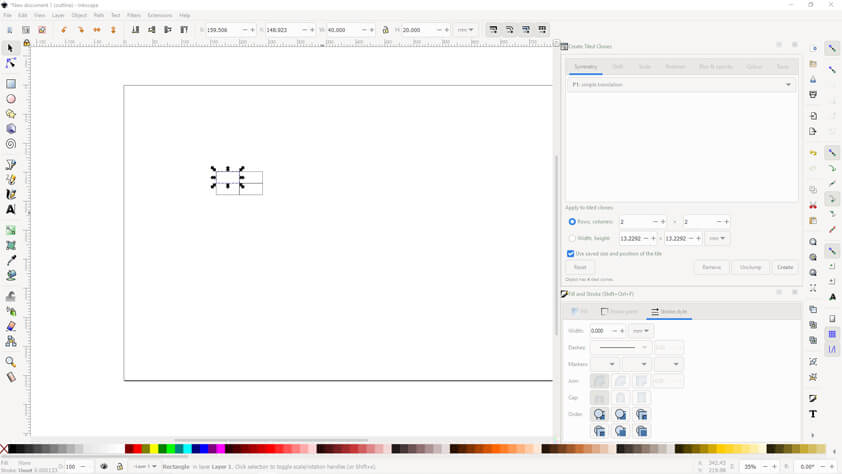
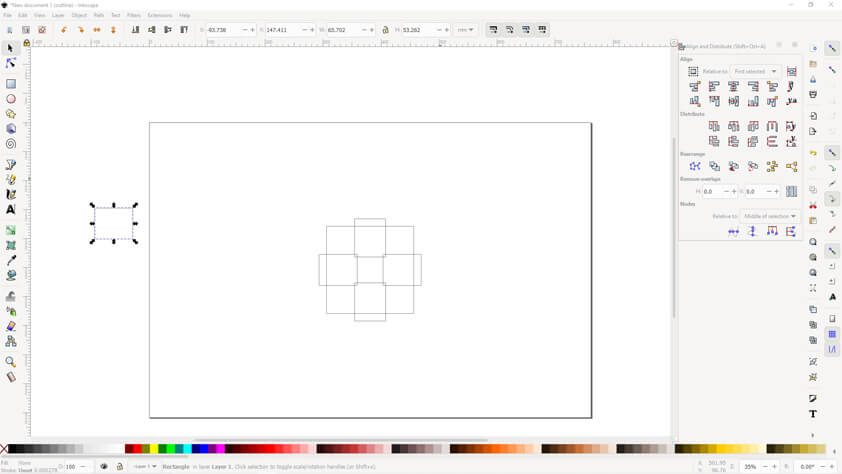
- 1. I draw a rectangle and specified its Stroke's size, then went into the Edit > Clone > Create tiled clones
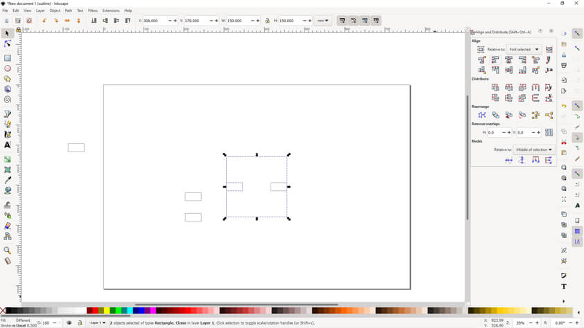
- 2. I went into Object > Align and Distribute and put my object in the center of the page horizontaly and vertically
- 3. I used the previous tool to place all the rectangles-clones on a square edges
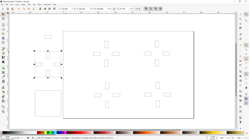
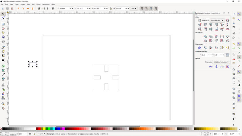
- 4. I tried to modify the original object but the result wasn't the expected one
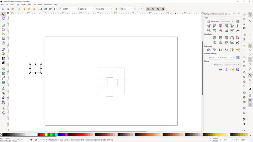
- 5. I tried again maintaining the "shift" key and the clones are modified symmetrically
- 6. A clone can be cloned and grouped, it seems to offer a lot of possibilities
▸ FreeCAD
I tried to use FreeCAD for the first time, it is difficult at first sight because the interface and everything is so different from Fusion 360. I found a tutorial that I reproduced to help me understand how to use FreeCAD to make a parametric designs. I chose to design parametric gears because I had already been looking for a way to draw gears, and at the time I found what I was looking for using Gear Generator. There is a tool in FreeCad to do that.
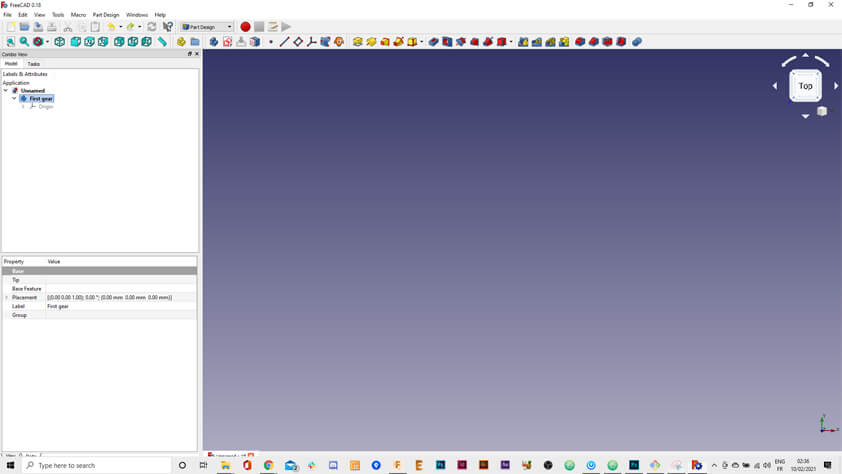
- 1. Create a new body in the Part Design Workbench
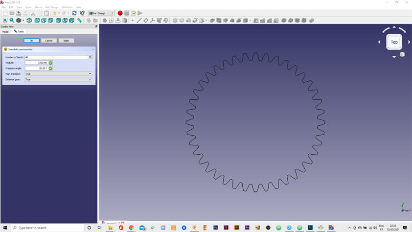
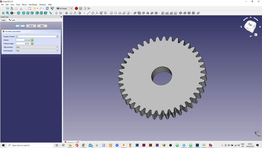
- 2. In the Part Design menu, select Involute Gears : a tool to create gears by specifying the number of teeth, the modules and the pressure angle
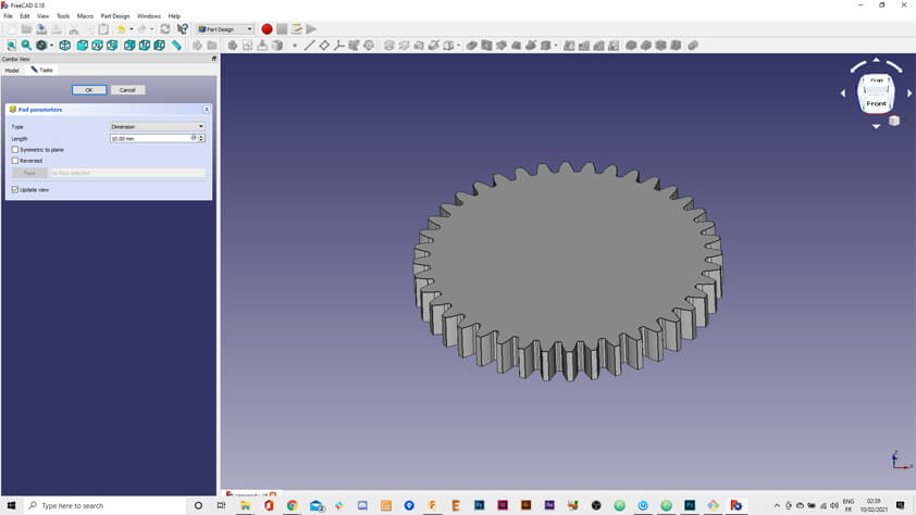
- 3. To pad the sketch = to extrude in FreeCAD.
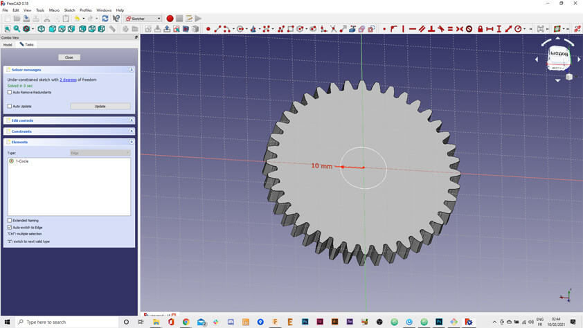
- 4. I draw a circle a applied a constraint to its diameter, then I used this sketch to create a pocket in the gear
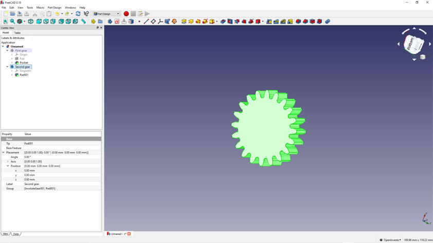
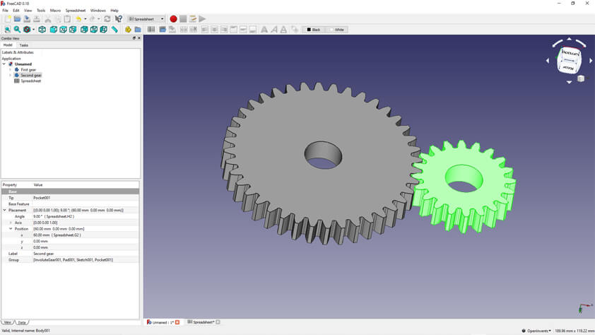
- 5. I create a second gear, and I repeat step 2 to 4
- 6. I don't know FreeCad shortcuts and I don't understand how to navigate in the FreeCad interface. This link helped me understand how to use my mouse. Later I learned about the space bar to hide parts of the design.
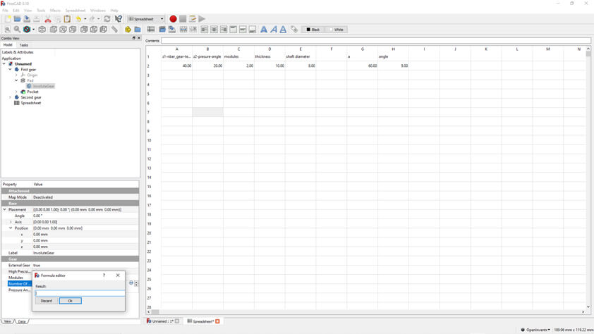
- 7. Create a spreadsheet in the Spreadsheet Workbench and specify your current datas, and formulas, then in the combo view you can assign cells value from the spreadsheet, to the properties of the design parts.
- 8. Using formulas can also be used to change components positions
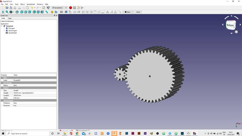
- 9. When it is all set, changing the values in the spreadsheet changes the design preview.
This tutorial helped me a lot to grasp the very basics of a parametric design using FreeCAD.
▸ OpenSCAD
I made a quick test on OpenSCAD using this tutorial from the Fab Academy 2017. I was surprised when looking for how to navigate in the interface. I found it very intuitive for the few things I've tried. Unfortunately Geometry using x,y,z and numbers is not my thing, but using OpenSCAD could be a way to improve this.
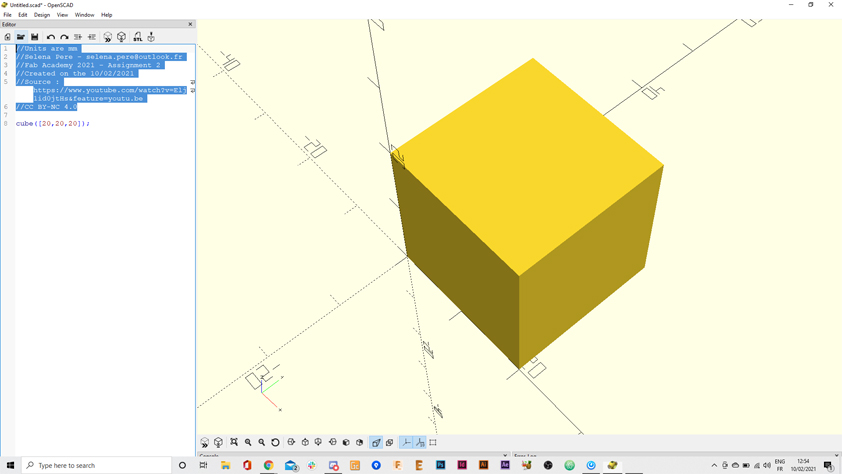
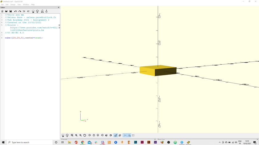
- 1. I open the software, and create a new file, in which I initialize a cube :
cube([20,20,20]);. When pressing F5 the preview appears. I specify units and general informations at the top of the document. - 2. By adding
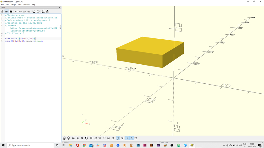
center=truewe can center the volume on the x,y and z axis - 3. I used the translate function to change the cube's position. Then I saved the project as an STL and as an OpenSCAD project.
▸ Fusion 360
My experience on 3D modeling software is light. So far I was only using Fusion 360 to model 3D parts for my projects, things for which I had already precise measures and a clear idea of the shape it should have - So this week is full of new things I've learn using Fusion 360.
Components
Yes, so until this week I had no idea what components were in Fusion. I begun by watching tutorials, this one from Lars Christensen on Youtube particularly, this was really helpful and I could manage the parts of the design I was working on. It also gives an idea of how to use the parametric tools. I tried a little but I design those models without parametring them.
Adding custom material
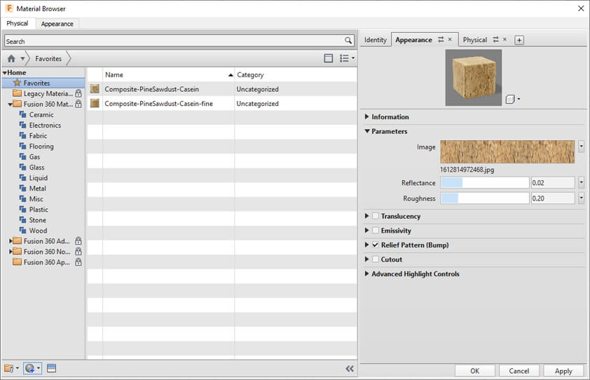
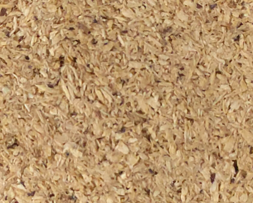
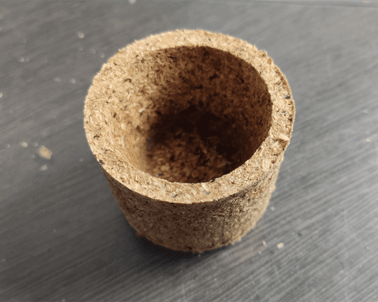
For my final project I would like to use the composite material from sawdust and casein glue that I am working on, so I had to add my material to my Fusion library. To do so I had to open the Material Browser (Fusion menu > Modify > Manage Materials), to create a new material and to add a picture of my material. The quality isn't perfect but it gives a better idea of what it could look like. Specifications on the material appearance and its physical propeties can be added, I don't have those informations so I left blank spaces. The size of the sample is also to specify, I chose a small surface, as my samples are small. I should take a better picture to get better results.
Designing external files
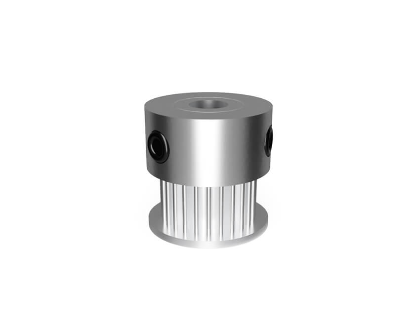
I designed some common parts of my projects outside of it, this way I can link it to several project easily. Again, this is very helpful in order to have a structured file. This is a little bit cartoony, but at least I have the right proportions. The first image comes from this "belt kit" on amazon.
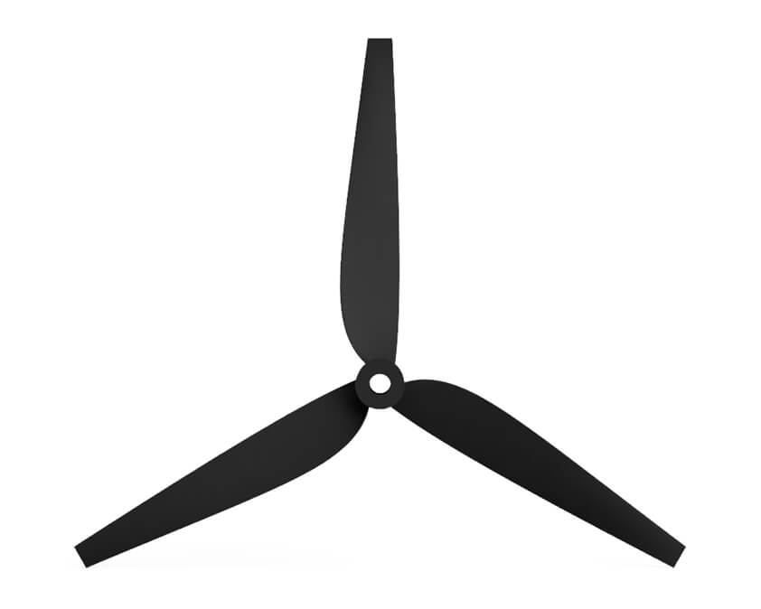
I had already designed a propeller using fusion 360 a while ago, and I couldn't make it again. This is a big frustration of mine for this week, it took me hours not to succeed in using the loft tool in order to make a propeller. Fortunately I found an helpful tutorial which wasn't using it. I learned to use Slots and Constructions panels using this tutorial.
Rendering with Fusion 360
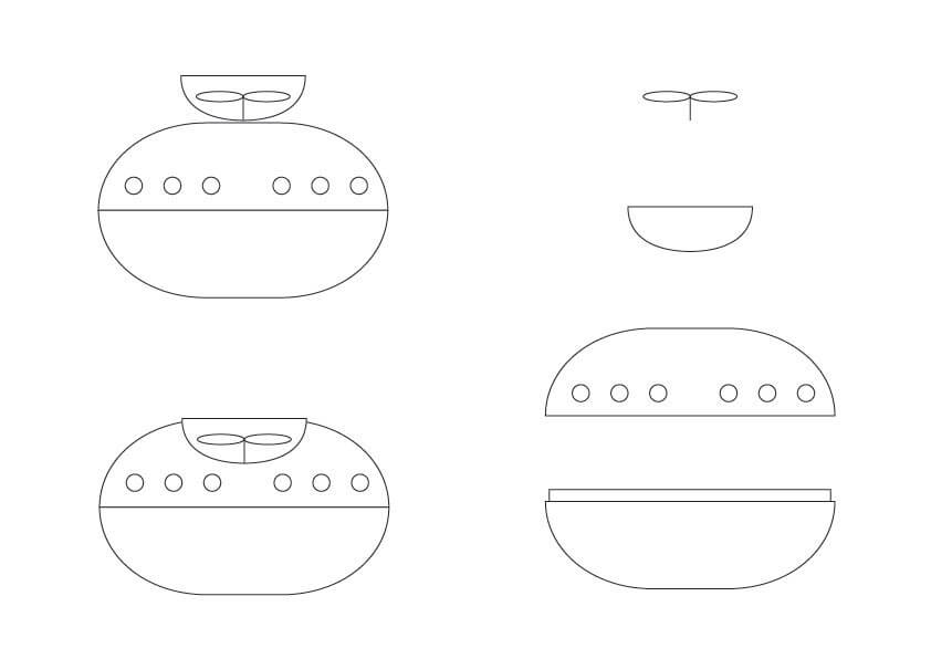
▸ Blow controller
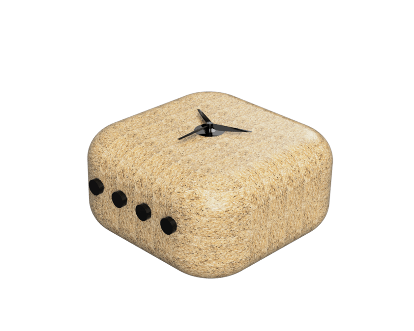
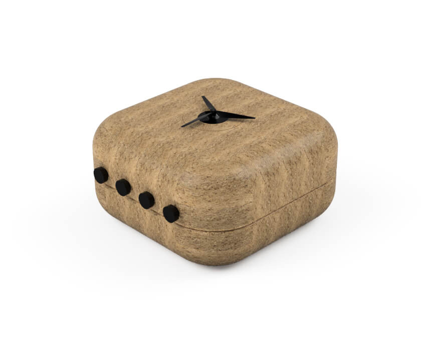
I tried to model the controller first, my main issue with it was modeling the propeller. Here is a video capturing the history of steps in Fusion 360.
Here are two render with the composites samples I added in my library, the size of the sawdust is different and I forgot to turn off the glossy appearance of the material on the first render.
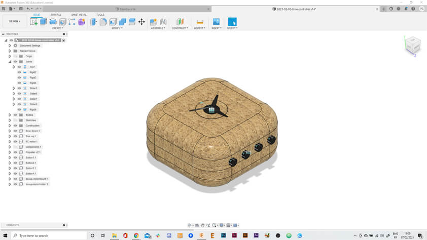
Assembly joints
The third image above shows the assembly joints icons on the model. At the end of the Blow Controller video on Vimeo, there is an animation of the propeller. I applied assembly joints to my objects where it belongs. The proppeler can turn, and the buttons a moving in the right axis with limitations added to get the right movement. I found limitations to this when trying to "articulate" the Sketcher 2 as I couldn't apply slide joints to miroring objects/or I couldn't change the side or rotation and it caused this problem.
Here is the model on Sketchfab :
I tried the animation tool of Fusion 360 and made this exploded view. The buttons are in the wild. It was a fast try, I'm not sure I understood how to use this tool properly.
▸ Sketcher
I was disappointed in me with this one. I tried to replicate the system from my previous prototype by 3D constructing it, then, when taking a break and just looking at it, I realised this system couldn't work. I was using simple wires in my previous prototype, and the belt isn't as flexible. Here is the video of the hystory conception.
Still, there is a screenshot from my window and a render of this disfunctionnal system.
I tried to make my first render using the Fusion 360 tool, in order to apprehend what the material would look like. Sketcher in the snow. I am surprised by these render.
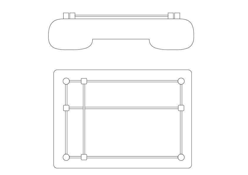
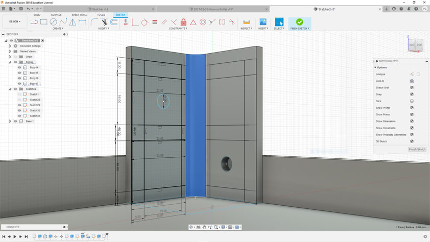
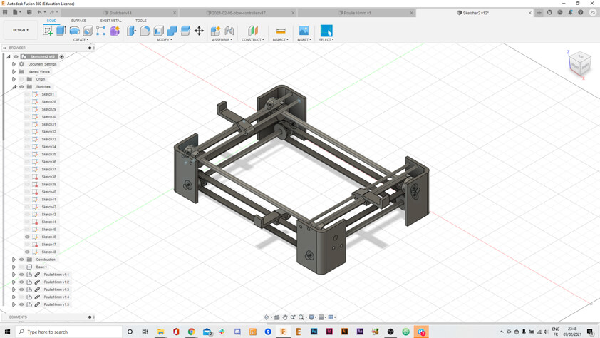
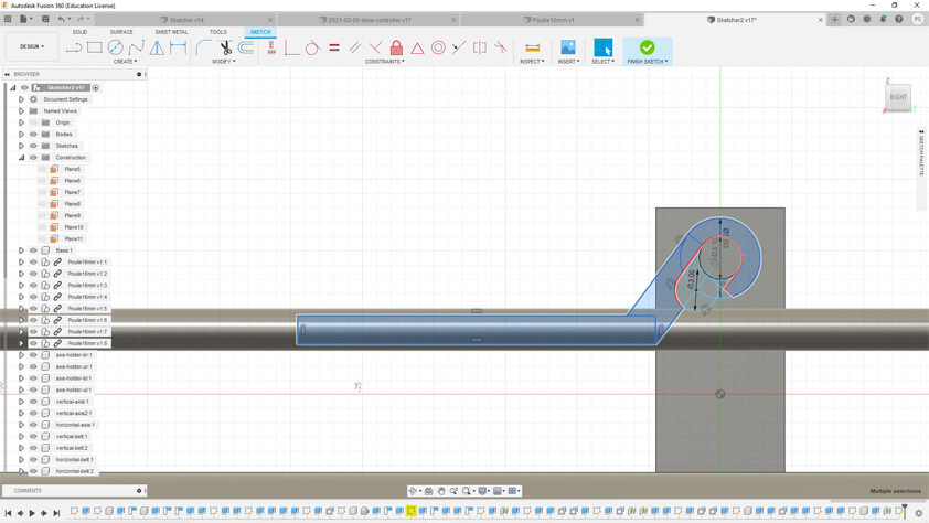
▸ Sketcher 2
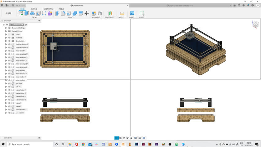
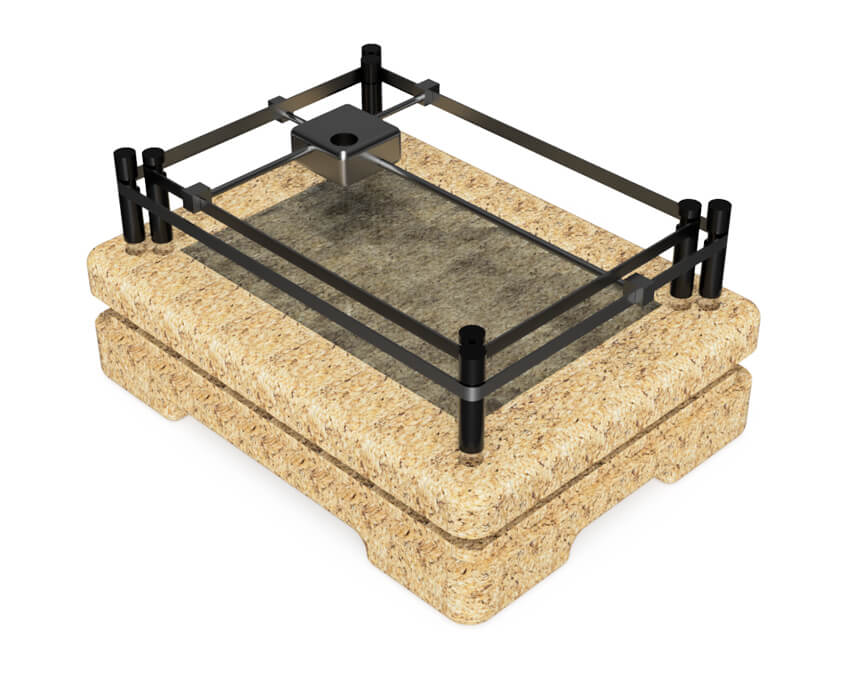
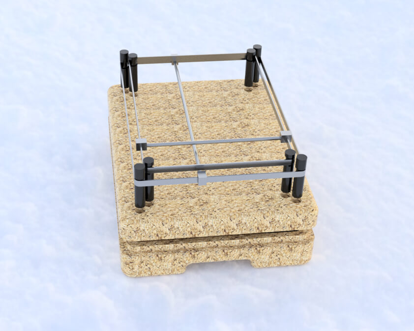
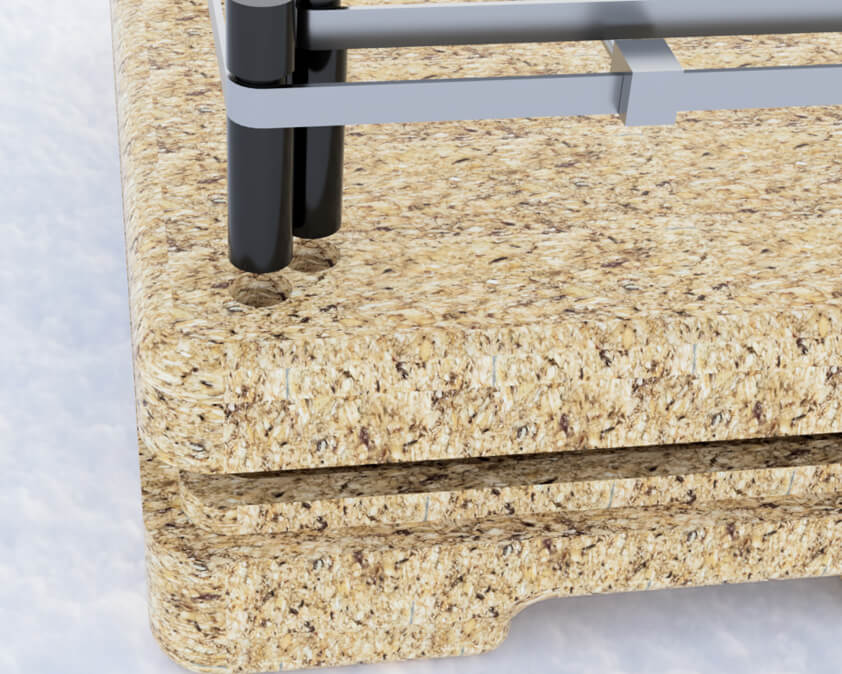
As the previous system couldn't work I tried to think of another system to make this sketcher using belts, which would increase the precision in contrast with wire and rubber. I draw this system, in which two perpendicular axis are carried by arms moving in parallel. The Pen holder is clipped on those axis.
Here is the history of the conception in Fusion 360.
I use sketches to make construction grids I can repeat so everything is symmetrical. I used constructions panels to adapt new components to my model, the last image is the pen holder profile.
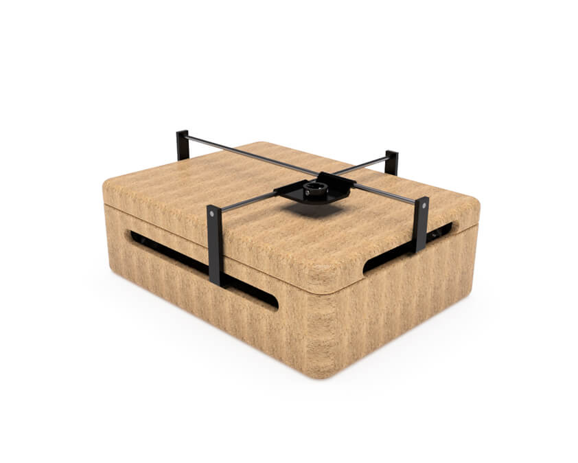
I am really satisfied with those renders. 3D modeling is pretty satisfying and much more clearer to convey a "mechanical" idea, it would have took me hours to draw a single proper view of it. It took me hours, but we can move in it and this is pretty exciting.
Here is the model on Sketchfab :
Sketcher 2 by Selena Pere on Sketchfab
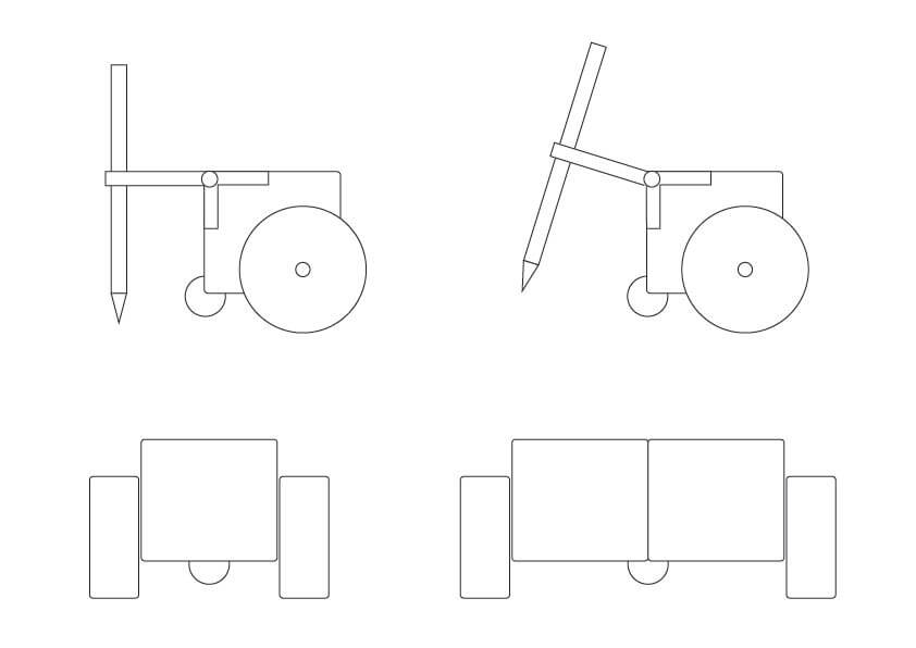
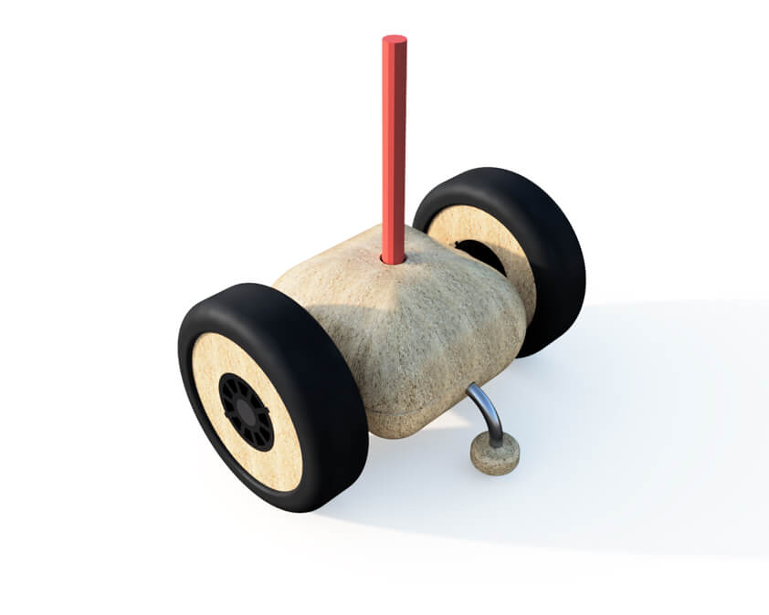
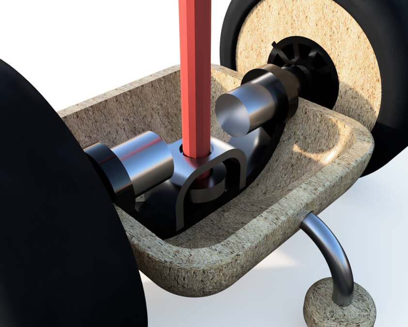
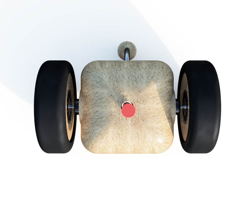
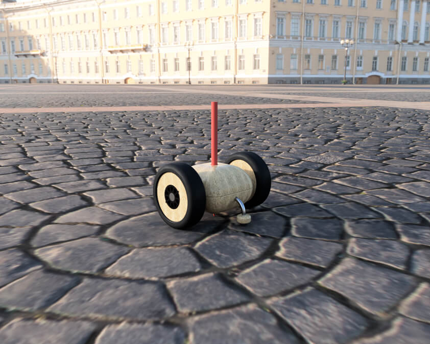
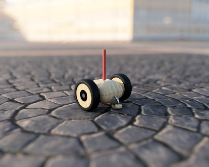
▸ Drawing Car
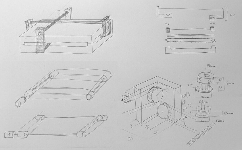
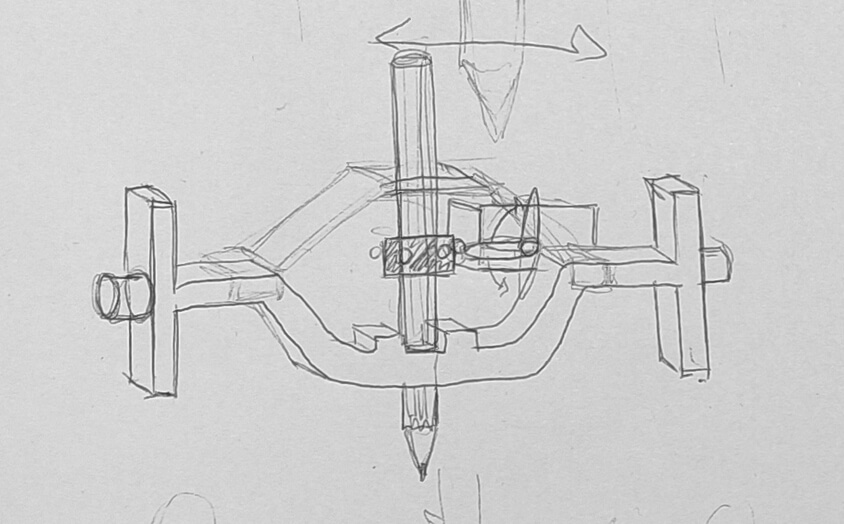
What I want to improve from my previous drawing car is the pen holder. I would like to add a servo motor to carry the pen holder, so that the pen is not constantly touching the ground. Here is a sketch of this system.
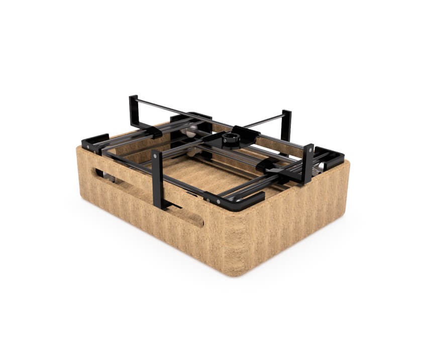
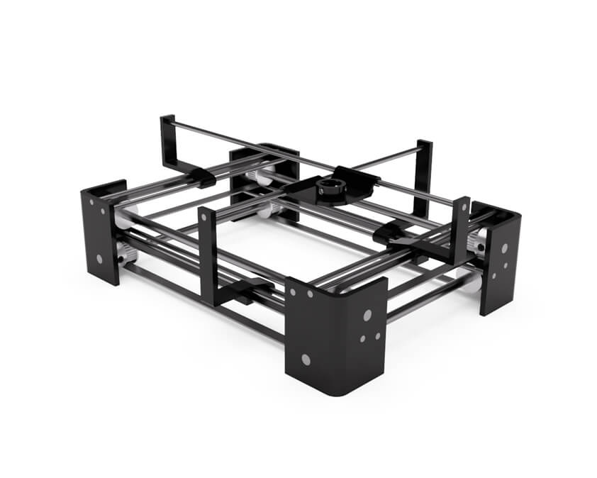
I design a frame on which this system could be placed, trying to optimize space. The motors are not modelize from real ones, so this model is not totally accurate regarding measures.
Here is the model on Sketchfab :
Drawing Car by Selena Pere on Sketchfab
I tried more rendering options with environment, several lightning parameters, and depth of view.

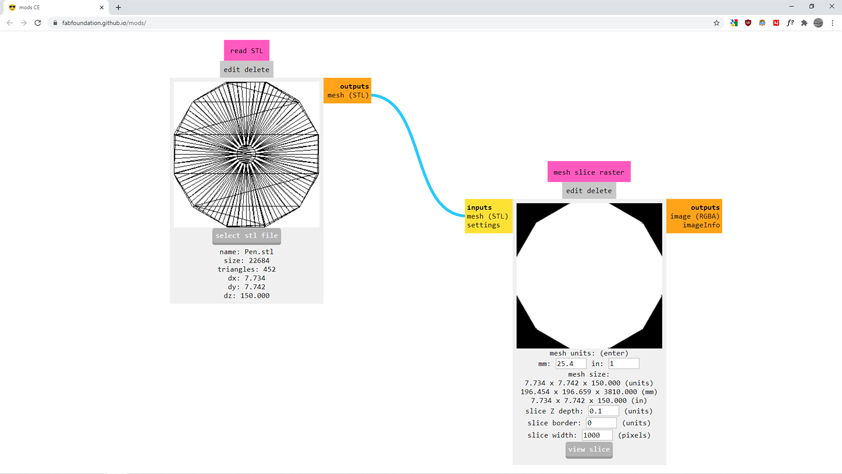
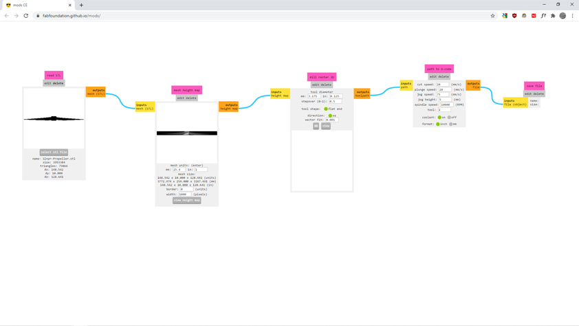
▸ MODS
In comparison to Mods, Inkscape and FreeCAD are delightful. I tried to use Mods but I didn't find helpful tutorials, appart from those regarding Minecraft Mods. I tried several Read modules, to read STL and PNG files, I tried to assemble modules but apparently I was doing it wrong as nothing happened. I need help for this part.
▸ My files
Here is the link to my Sketchfab profile. The link under the name link to the file on Sketchfab, the links next to the name are previews using the Autodesk Viewer. The limitation of Autodesk viewer is that it is necessary to extend the validity of the link every 30 days. Regarding source files feel free to contact me.