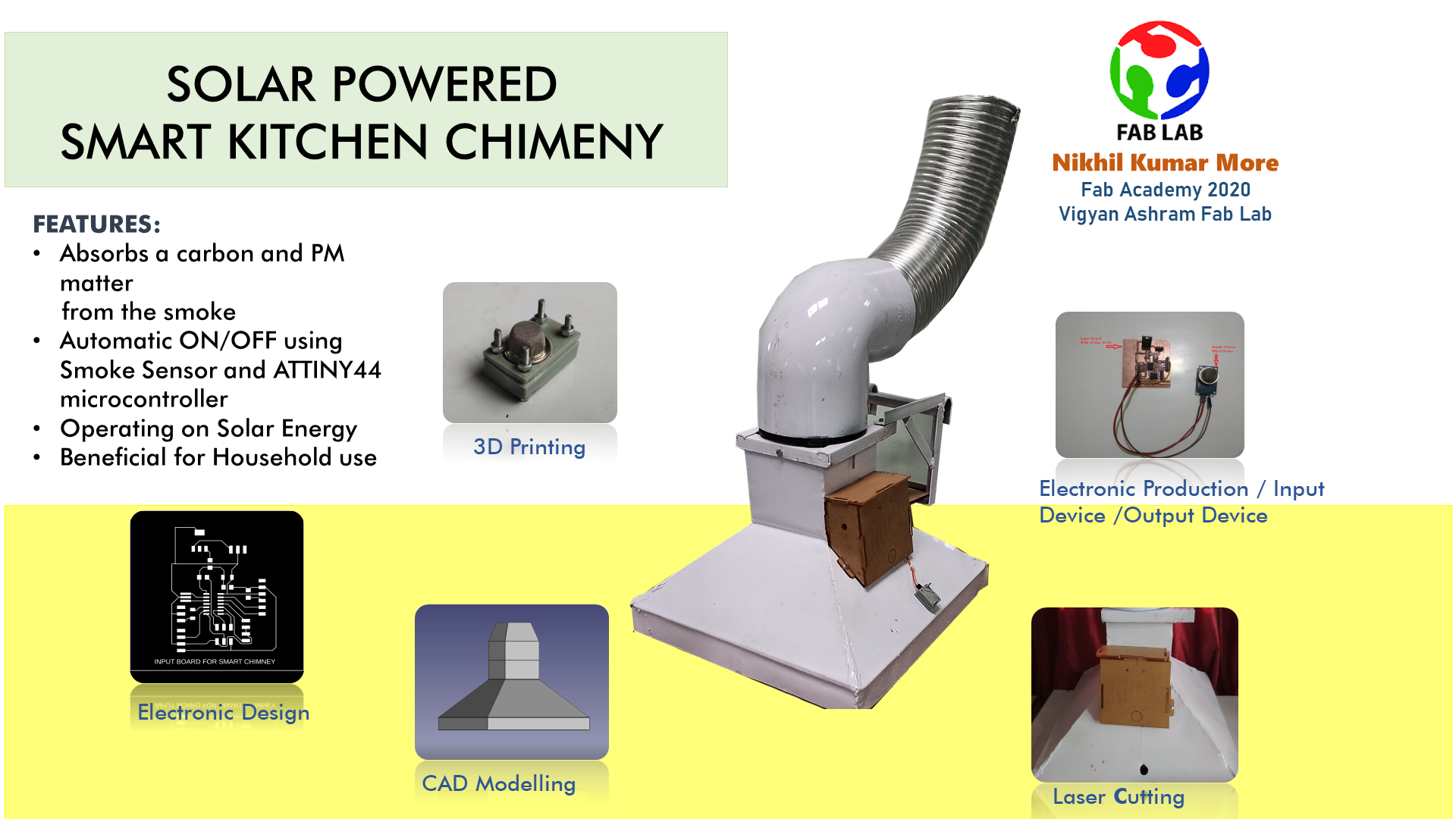
Solar Powered Smart Kitchen Chimney
Scope of the Project
•In India, the biomass is used for generation of heat for cooking process.
• In rural area, the biomass is available in huge quantity.
• The burning of biomass, can release smoke and high concentration of particulate matter.
• Which dangerous for health of person working in kitchen and person who will come contact with the smoke.
• So, it is necessity to absorb this smoke from kitchen, before it gets add into the atmosphere.
Abstarct
A smart kitchen chimney uses the solar energy as a power source the run the DC fan of the chimney. When the smokes come in contact with the sensor of chimney, the signal will gets to Arduino microcontroller, the exhaust fan will get operate, which can absorb the smoke from kitchen and send it into carbon charcoal filter where the carbon and other hazardous gases will get absorbs and the smoke will exhausted into the atmosphere.
Introduction
The chimney is the passage through which smoke and combustion gas escape from workplace
to outer environment. The existing chimneys are operated based on AC source which is more costlier and some places the electricity is not available.
In order to overcome this difficulty our entire system works on DC source.
From solar panels we get sufficient DC supply to operate the entire system. Solar energy is a renewable energy which we can generate at low cost.
The normal exhaust fans in household as well as in all other workplaces have a manual speed control system. it is regulated using a rotary switch which
internally involves a potentiometer, the potentiometer adjusts current flow to the exhaust fan and hence,
the speed is adjusted this system creates a few problems in terms of user comfort. To avoid this automatic on/off control technique is implemented
in our proposed system.
The automatic on/off control process of exhaust fan is made by Arduino microcontroller and smoke sensor. The smoke sensor detect the smoke more
accurately and send required data to exhaust fan module and the fan get operate.
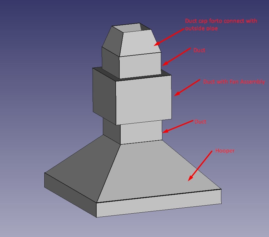
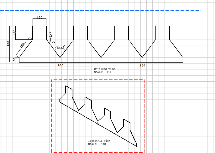
Sketch of project
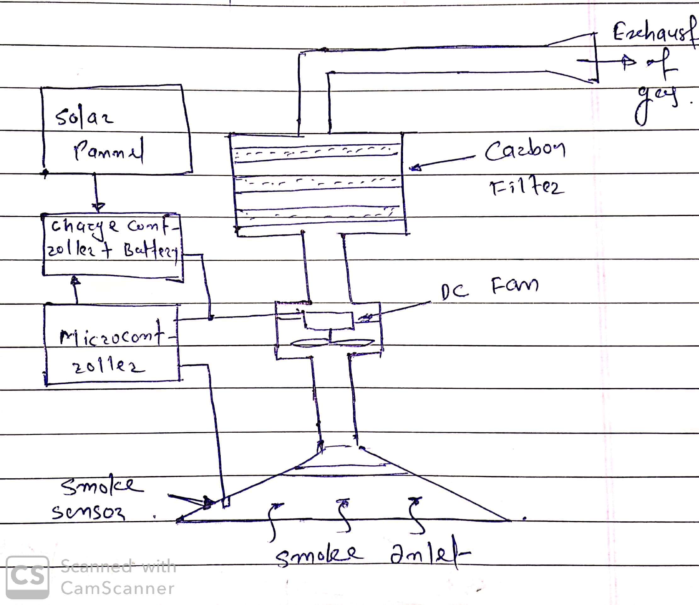
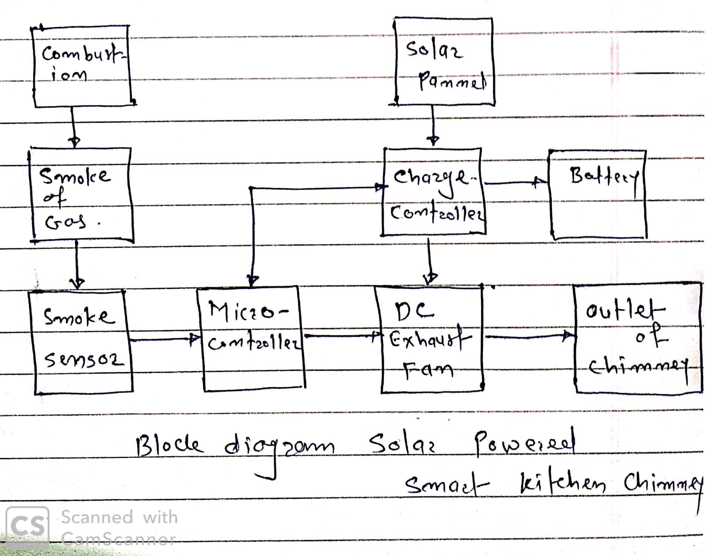
Block diagram of Project
Literature Survey
Yu et al. (2015):A relatively low number of smokers have caused high lung cancer prevalence in females in Taiwan.
Since cooking is one of the major sources of particulate matter (PM) and polycyclic aromatic hydrocarbons (PAHs) in household buildings, one of the major risk
factors for lung cancer is suspected to be the exposure to air pollution from cooking (APC) [1].
Gao et al. (2013):One of the major problems of indoor air quality and indoor environmental health identified was the particulate matter generated during the
cooking process. Accurate information of emission characteristics especially the size distribution is re-quired by reliable assessment of exposure to cooking
generat-ed particles. The volume/mass-based size distribution of the fume particles at the oil heating stage for the typical Chinese-style cooking in a laboratory
kitchen is characterized in this study titled “Volume-based size distribution of accumulation and coarse particles (PMO. 1-10) from cooking fume during oil heating”
which was published in “Building and Environ-ment”[2].
Poon et al. (2016):The major indoor pollutant source is from cooking. To know both the exposure, inside and outside the kitchen are im-portant. Two indoor zones and
their spatial distribution of particle concentration however, have not been studied exten-sively. In this study, particle transport between two zones for a water
boiling process under four kitchen hood operation scenarios was investigated. By using a condensation particle counter the particles were counted and the study may be
con-sidered a study of ultrafine particles since most of the particles were less than 100 nm in diameter. Poon et al published their article in Building and Environment
and the title is “Experi-mental study of exposure to cooking emitted particles under single zone and two-zone environments”. [3]
Zhou et al. (2016):Occupant's health is determined by the pollutants generated from cooking process. Range hood is installed to exhaust oil fume and other pollutants for
conventional residential kitchen in hot summer and cold winter region of China. Air is sup-plied through the insect screen in typical kitchen. However, for good indoor
air quality in kitchen, this kind of air supply and exhaust system is not capable of providing air distribu-tion. The combined scheme with air supply through slot air
curtain and air exhaust through range hood is proposed in order to solve this problem, which is called as the push-pull ventilation system. To investigate the air velocity,
temperature and pollutant distributions both numerical simulation and field test were carried out. During numerical simulation Or-thogonal study was performed. “A pre and post
evaluation of indoor air quality, ventilation, and thermal comfort in retrofit-ted co-operative social housing” was presented by Zhou et al and also published in Building and
Environment
Component and its specification
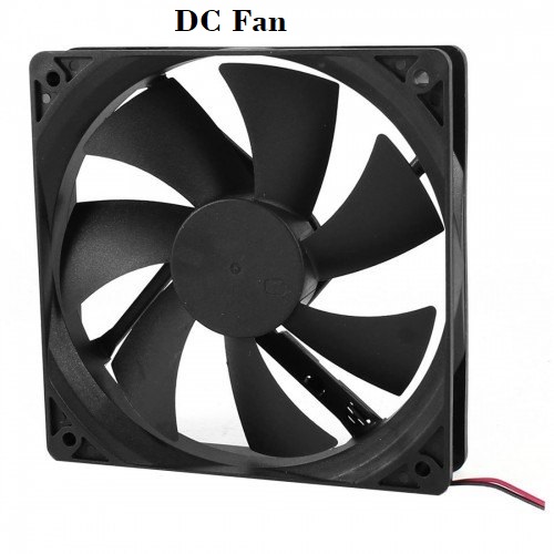
a. DC Fan
The fan is used to sucks the smoke from the kitchen, exhaust it into the atmosphere. Here i have to select the fan, which is work on solar power. so the DC fan is selected.
The propose DC fan have this specification:
Type: Axia Fan, Voltage:12V,Power:5W, Speed:2400 RPM, Size: 12x12x2.5cm,Air Volume:85CFM, Noise Level:35db
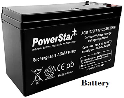
b. Battery
Batteries as electrical storage medium, are very important part of this system because it have to provide the energy when there is no sunlight
So here i have to used sealed lead acid battery.Following are the some calculation for battery size:
Load of Fan= 10W (5W x 2 Nos.)
Running Time (i.e. Backup required) = 6 hour/day
Total load on Battery = 10W x 6 hour = 60 WH
Consiter system viltage = 12 V
Battery charge required capacity = 60WH/12V = 5 AH
In solar PV system, the DoD( deep discharge) is in the range of 60% to 80%. So here consider 70%.
Therefore the required capacity of battery= 5AH/(0.7 x 100) = 7.14 AH.
In market the battery is availble with capacity 7.5 AH. So I selected this battery.
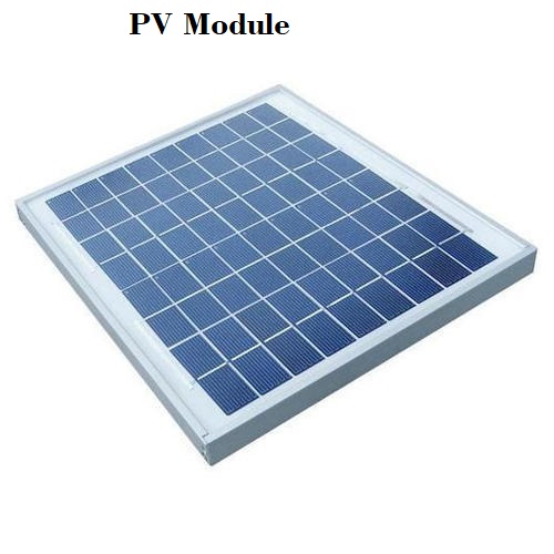
c. PV Module
A solar PV module is a collection of solar cells, mainly connected in series. These combinations of solar cells
provide higher power than a single solar cell. The PV module are available in the power rating from 3 watt to 300 watt. They really form the basic building block
of PV system as power generating unit. Here we required a energy from PV module for Battery Charging of around 7.5 AH. The power of battery is used to run a suction fan of
blower. The size of the PV module is decided by the following calculation
Power required for charging in Watt = Battery capacity in AH x Battery Voltage
P in Watt = 7.5 AH x 12 V = 90 WH (Watt-Hour)
Consider the battery charging time is 6 hour/day. So 90 WH/6H= 15 W
So here I selected thep pannel of 15 W or more 20 W depends on availability.
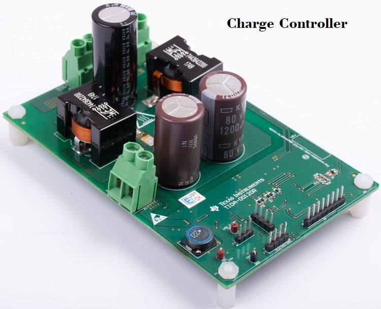
d. MPPT Charge Controller
The PV system required several components other than PV module.The batteries are required to store the electrical energy for night time applications. So here the protection of batteries is required from over-charging, over-discharge as both of these damage the batteries and reduce their lifetime. so the device which protect the batteries is know as charge controller. MPPT is used to ensure that PV module is supplying maximum posible power to the systems.In the absence of MPPT, the PV module may work in sub-optimal conditions and may not generate power to its potential. The charge controller and MPPT are club into single electronic device called MPPT charge controller. so here i have to design the circuit and to develop the PCB in Fab Lab
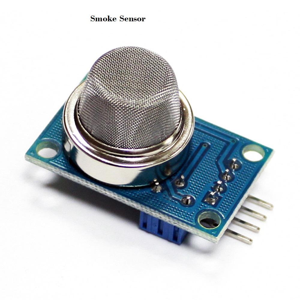
e.Smoke Sensor
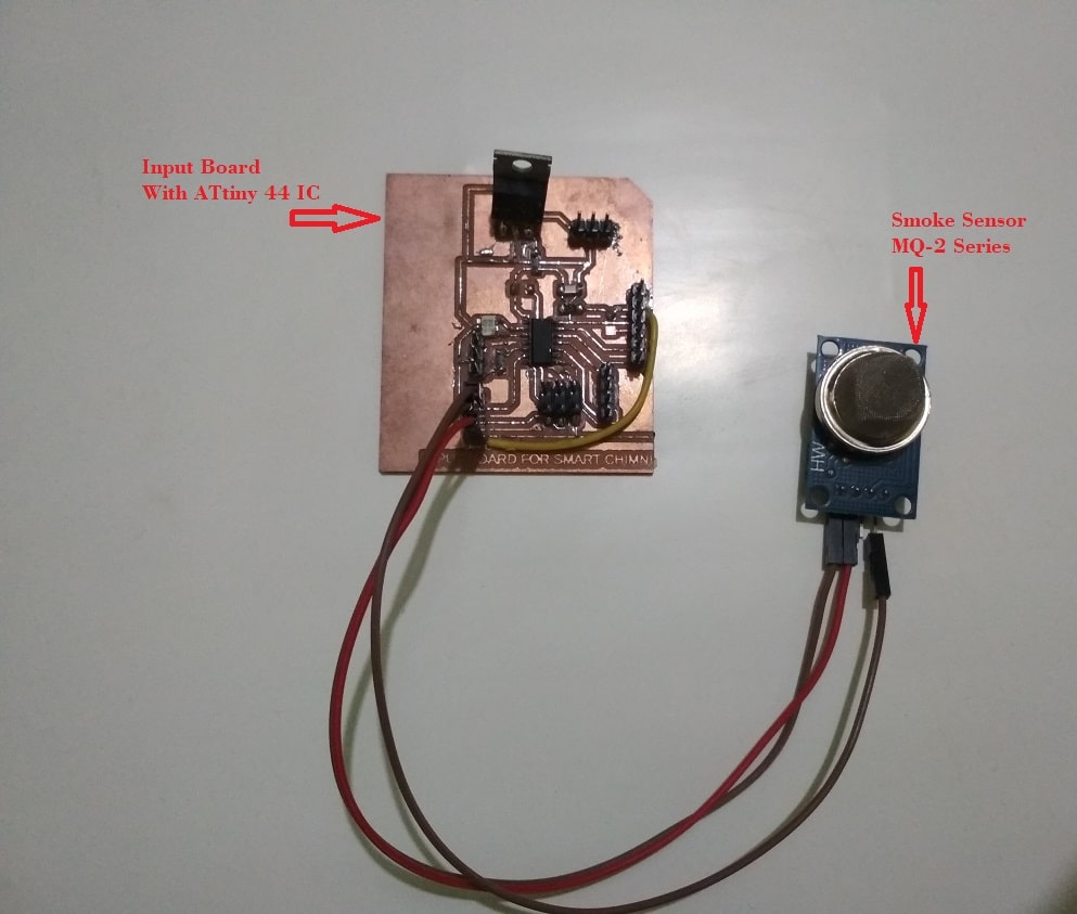
Smoke sensor sense the smoke which is coming from burning of biomass or gas in kitchen. After sensing the smoke it can gives the signal to microcontroller for to start the working of fan in chimney. Here I have selected MQ2 series smoke sensor module available in market. The sensor has four fin VCC, GND, AOUT and DOUT. For more details, download the datasheet here
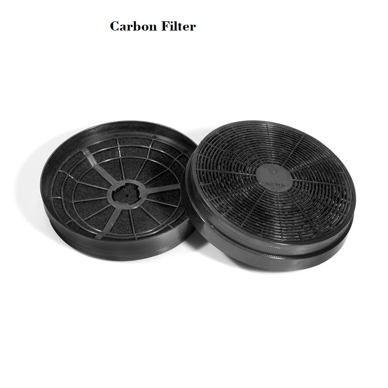
f. Carbon Filter
The carbon filter is used to absorb the charcoal from the smoke.
h. Microcontroller
A microcontroller is a compact integrated circuit designed to govern a specific operation in an embedded system. A typical microcontroller includes
a processor, memory and input/output (I/O) peripherals on a single chip. A microcontroller is embedded inside of a system to control a singular function in a device. It does this by interpreting
data it receives from its I/O peripherals using its central processor. The temporary information that the microcontroller receives is stored in its data memory, where the processor accesses it and uses
instructions stored in its program memory to decipher and apply the incoming data. It then uses its I/O peripherals to communicate and enact the appropriate action.There are a number of technology and b
business considerations to keep in mind when choosing a microcontroller for a project.Beyond cost, it is important to consider the maximum speed, amount of RAM or ROM, number or types of I/O pins on an MCU,
as well as power consumption and constraints and development support.
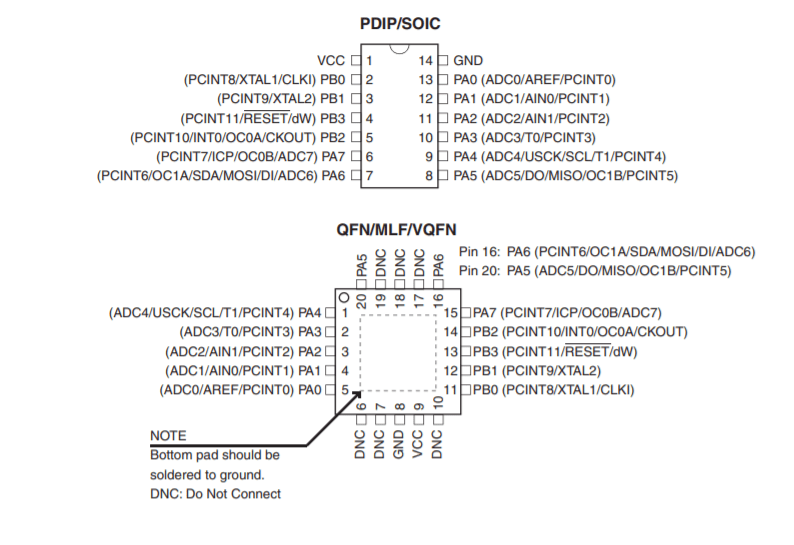
Here for smooth operation of the project, I have selected AtTiny 44 IC, which has 14 pin.
The details about this microcontroller is given in Assignment 9. The pin configuration is shown below:
Bill of material
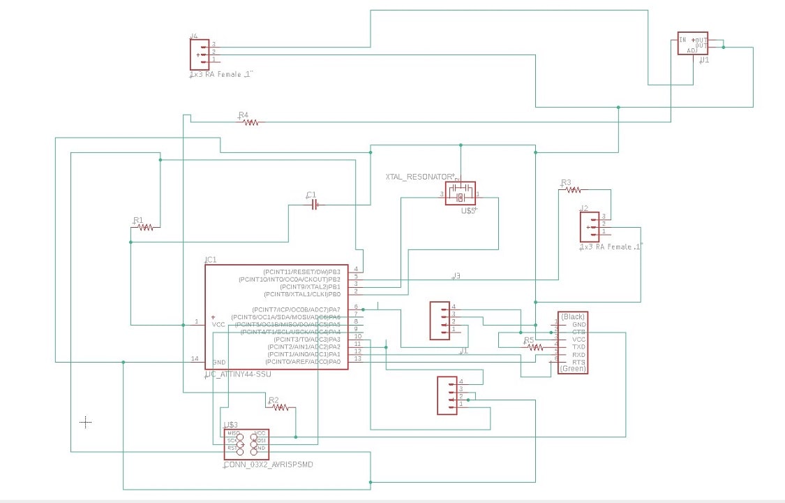
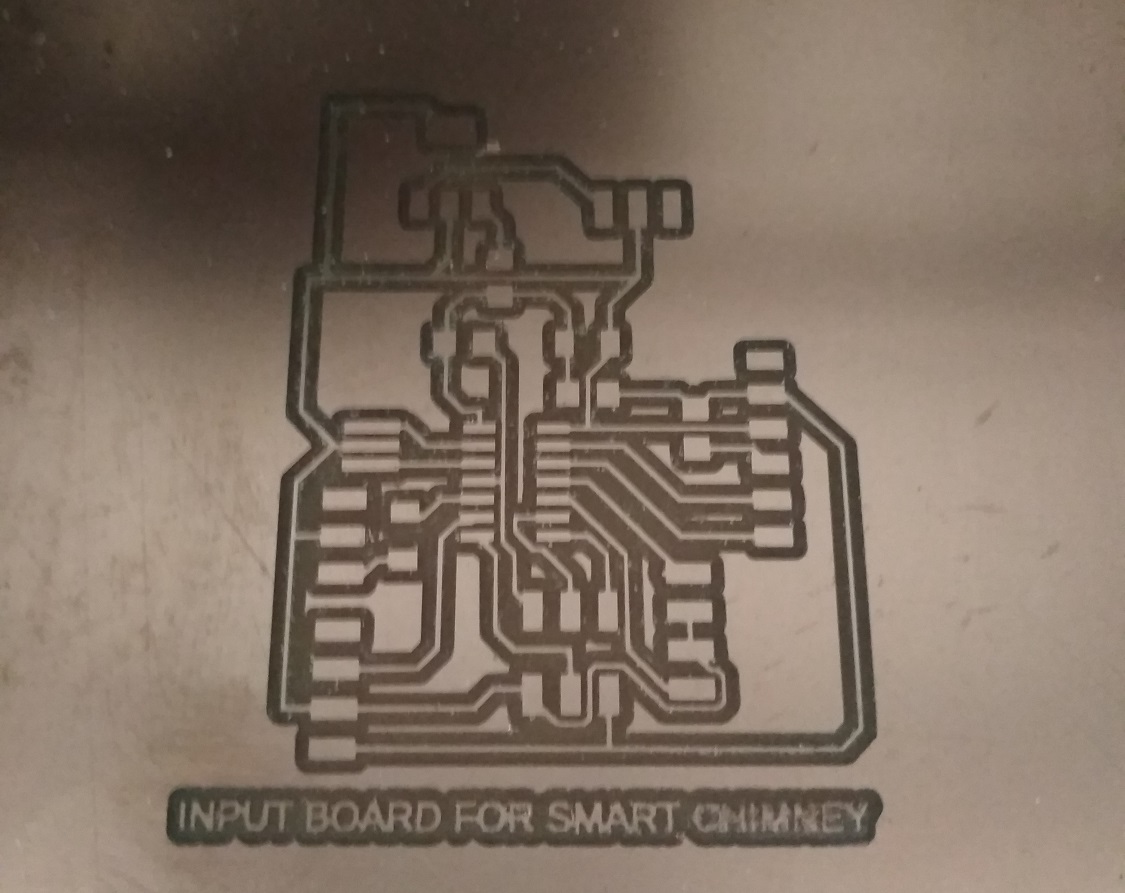
The input device board is designed using Eagle software. For the given project, the smoke sensor is act as a input device. When the smoke is detected by the sensor, the signal is send to the IC and according to that the output device start working.
So here I am using the module of smoke sensor, so the 4 pin are provided for connection. Out of 4 pin, Two pin is for VCC and GND and other two pin is for anolog and digital signal. So here only analog connection is made with IC, because I have to take only analog signal.
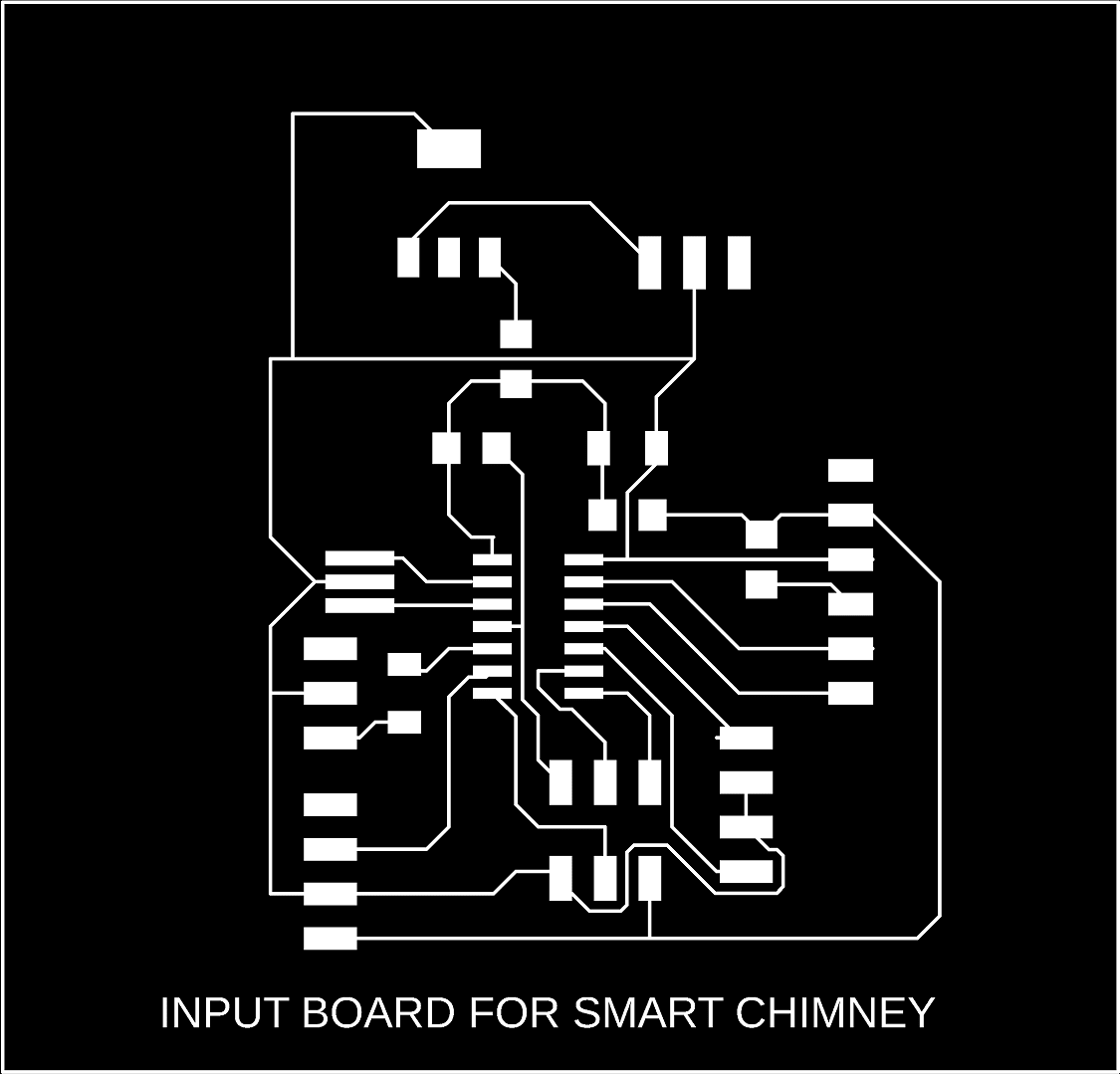
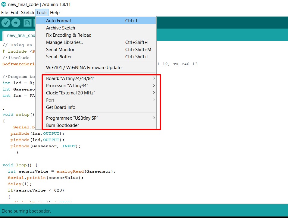
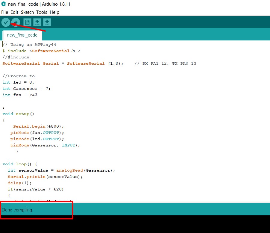
The schematic and Board diagram for input device board is shown below: The image is exported in png formatt, then the png file is converted into rml file using fab mods. The rml is loaded to the machine for trace and cut the PCB. The PCB after milling is here. For more details about this please go through my Assignment 10:Input Device Now the next work is component soldering, the list of component is here. Here I have created the programm in Arduino IDE, The borad has smoke sensor as a input and fan & LED is output. The LED and Fan will get HIGH when the smoke sensor read the value =>620. else it is LOW.
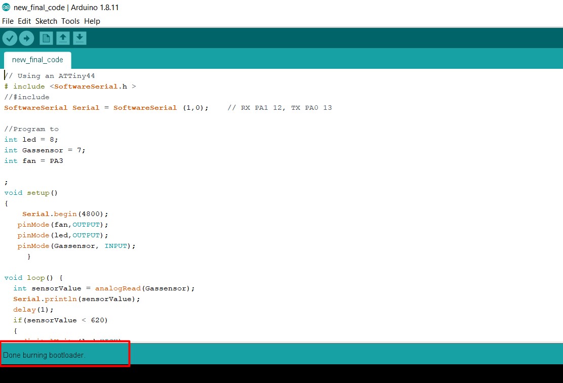
Firstly select the board, Processor, clock and programmer in tool menu.
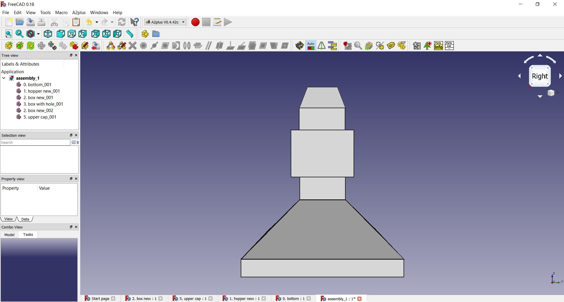
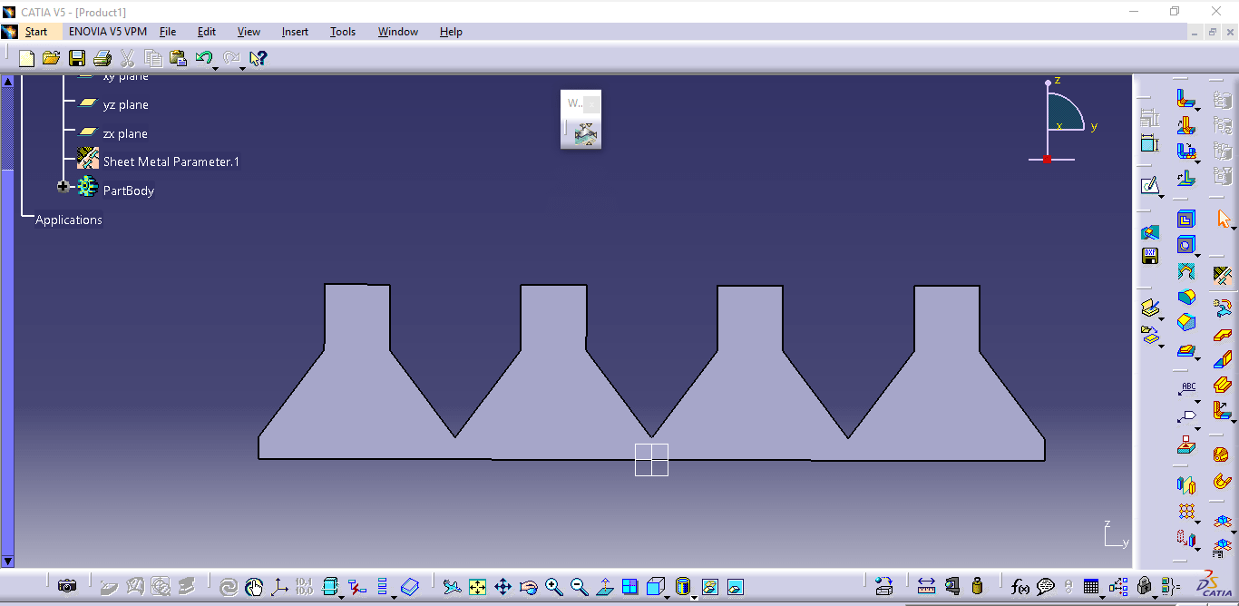
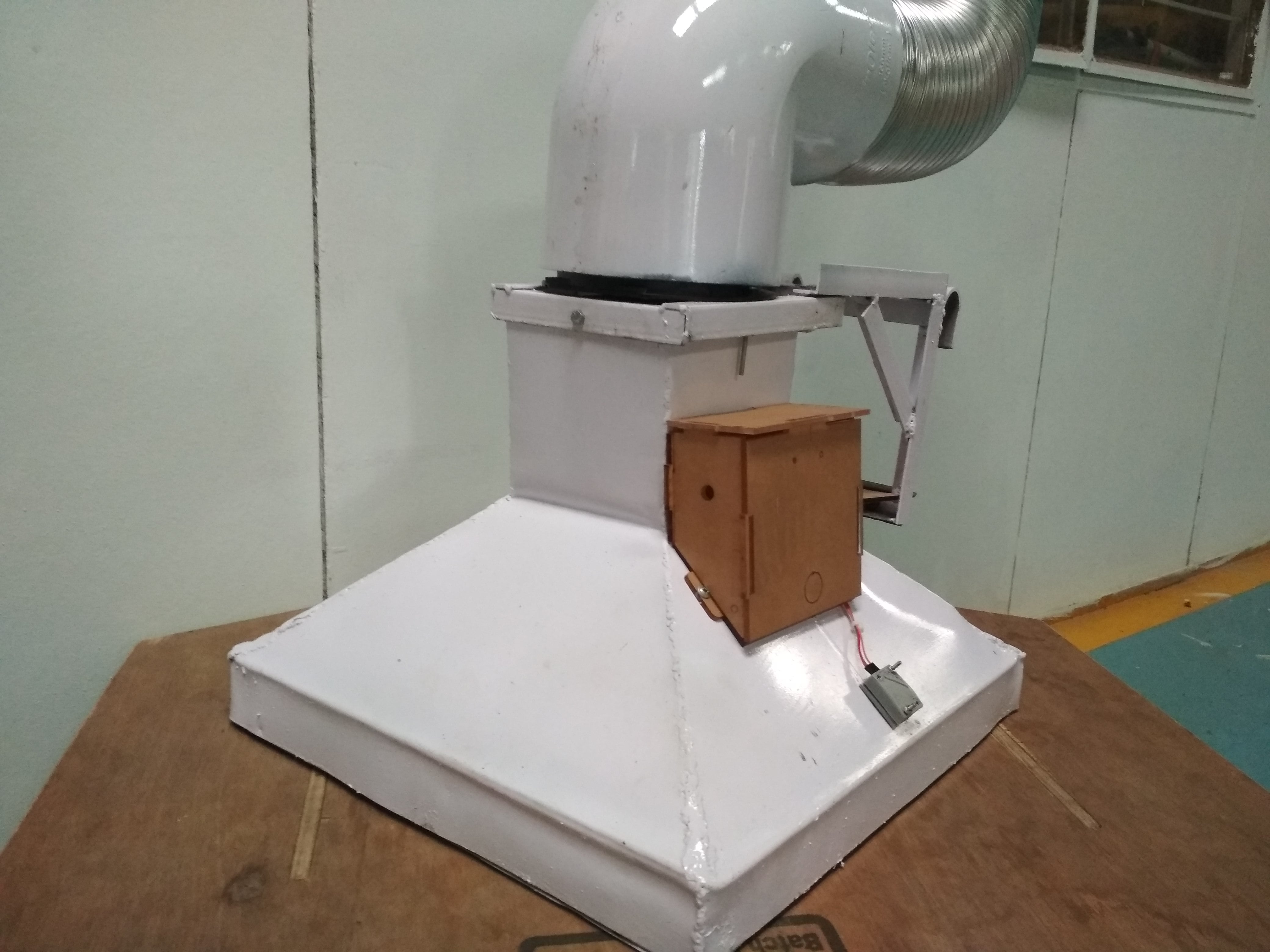
Then run the Burn Bootloader. Then compile and upload the code in the board The design of the smart kitchen chimeny is created usign FreeCAD software. Firstly I have created part seperatlly in software and finally assembled then A2plus workbench in software. According to this design, with some little changes, the sheet is designed in CATIA software for cutting on Plasma Cutting Machine. After the sheet cutting (the sheet is cutted from Plasma Cutting Industry, so photograph not available) the sheet bended with the help of bending machine and then welded by arc welding.
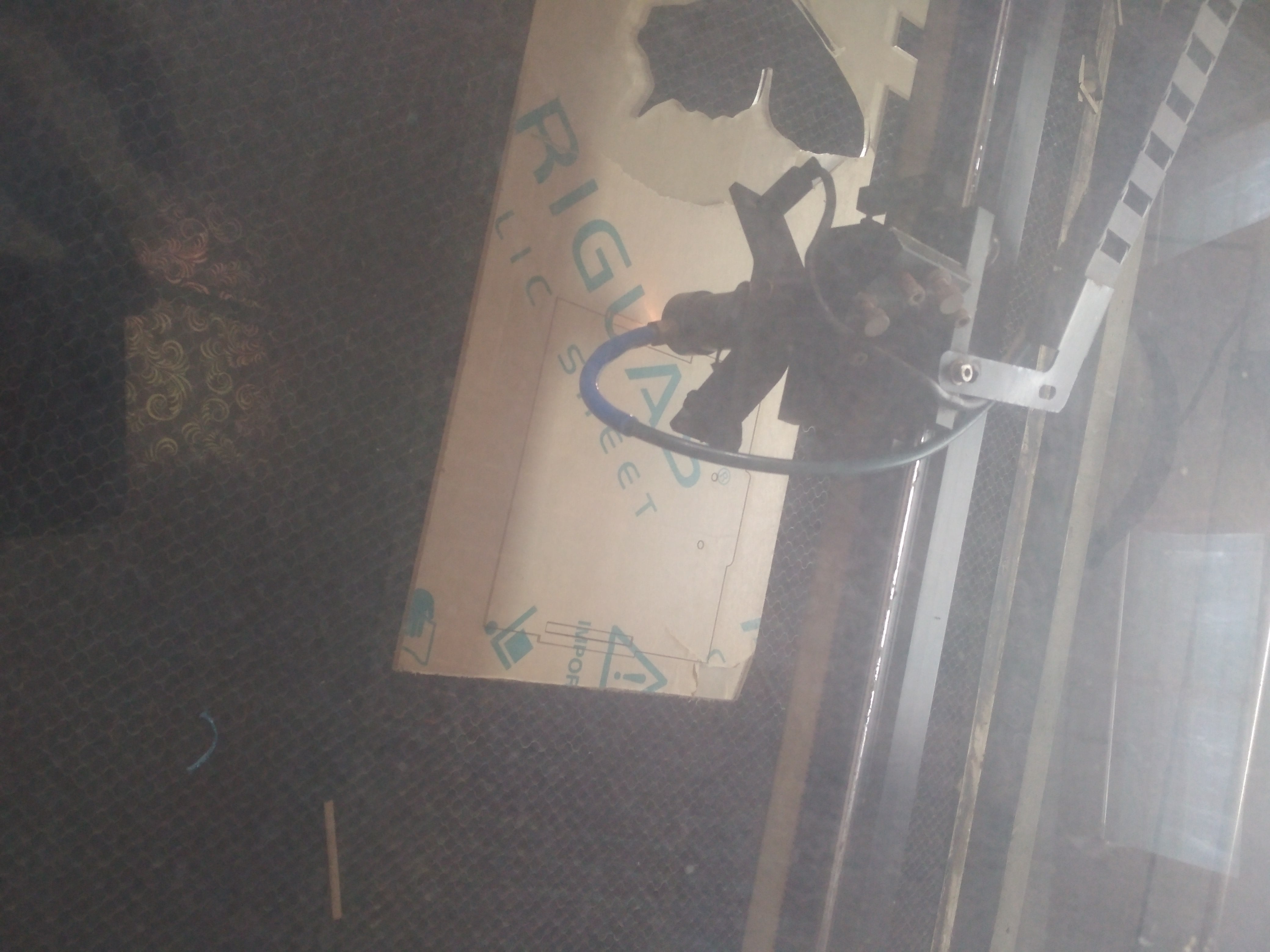
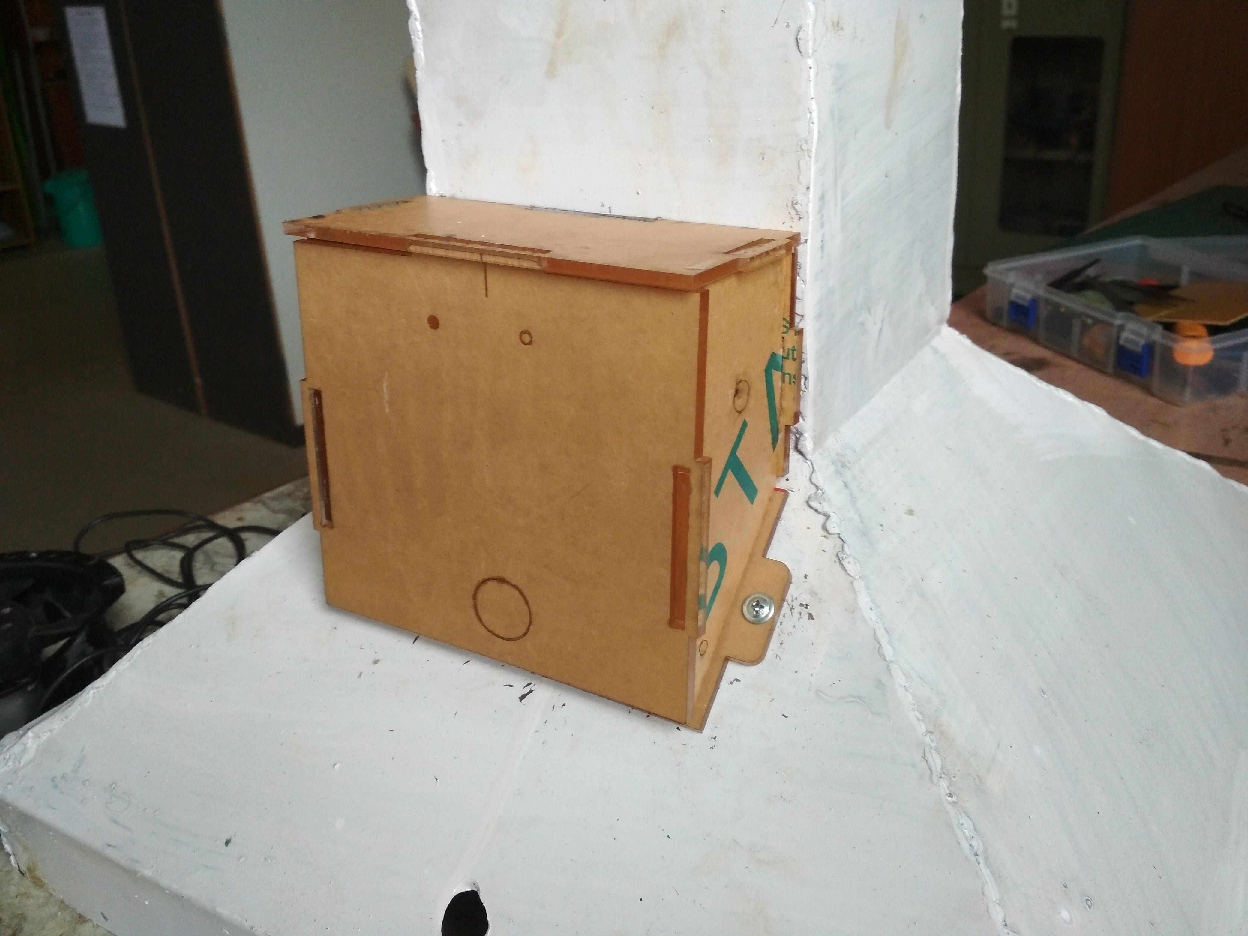
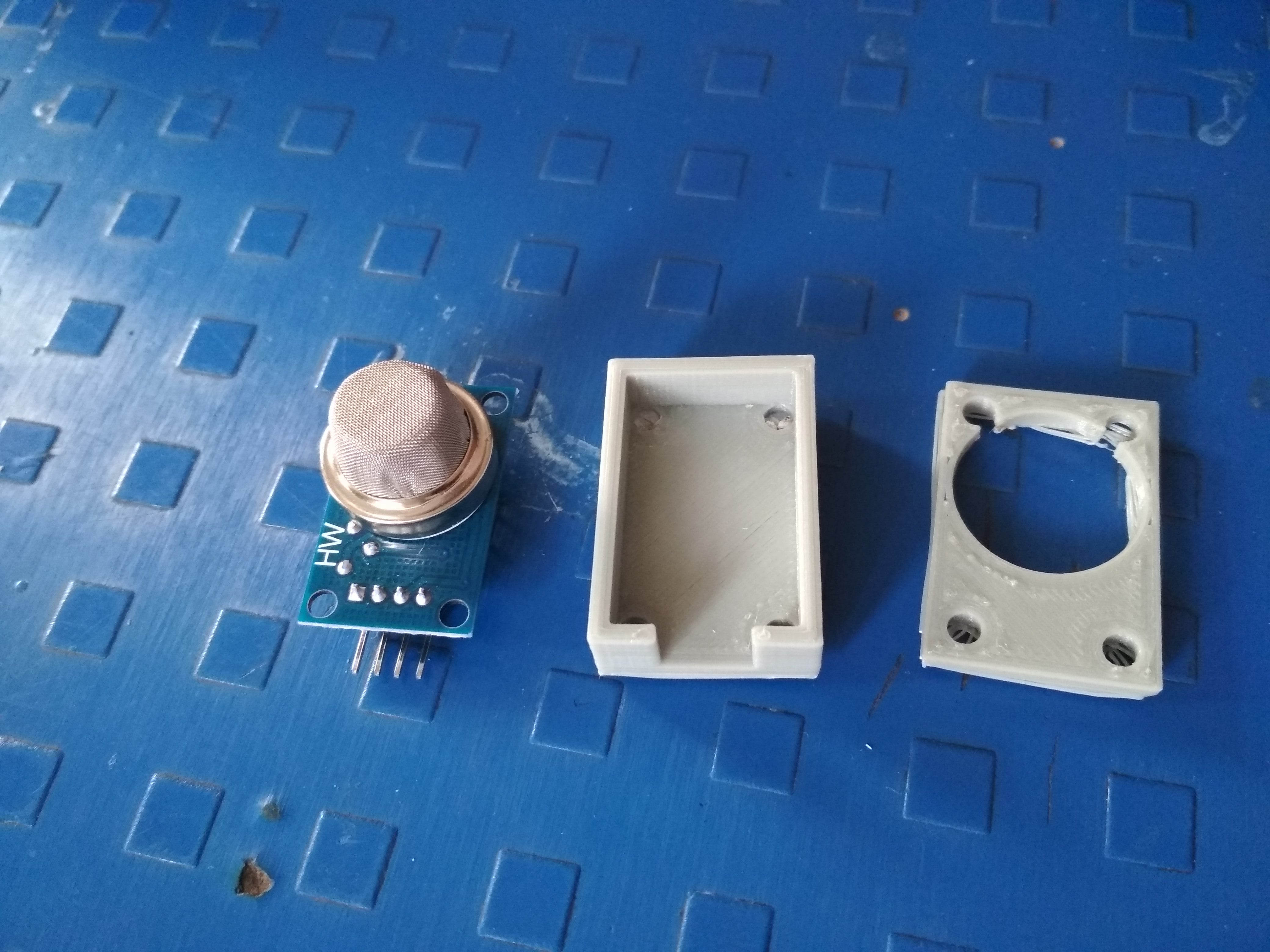
With the help of spray penting, body is coloured. Finally the body of the chimney is ready. For the packaging of electronic circuit on the chimeny, box of Acrylic sheet is developed on Laser cutting machine. Here is the photo during cutting the part of the box. The box is assembled, developed the box through press fit. Then the box is assembled on the body of the chimeny. Now I have to mount the smoke sensor on the body of chimney. It may comes with the contact with smokes, so we decided to develop the casing for smoke sensor.
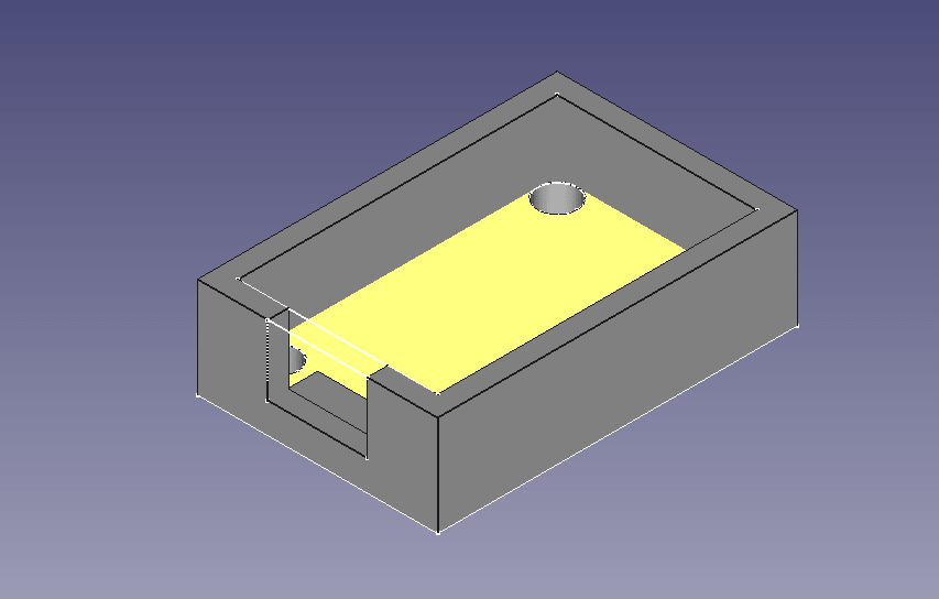
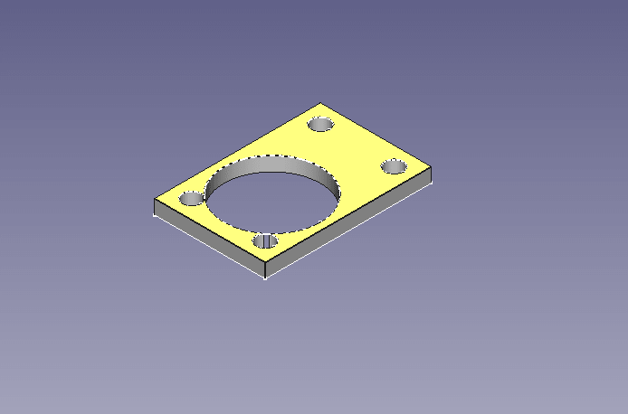
The design of the casing is developed in FreeCAD software. There are two parts of the casing 1. Box 2. plate. It will assembled with the help of nut bolt.
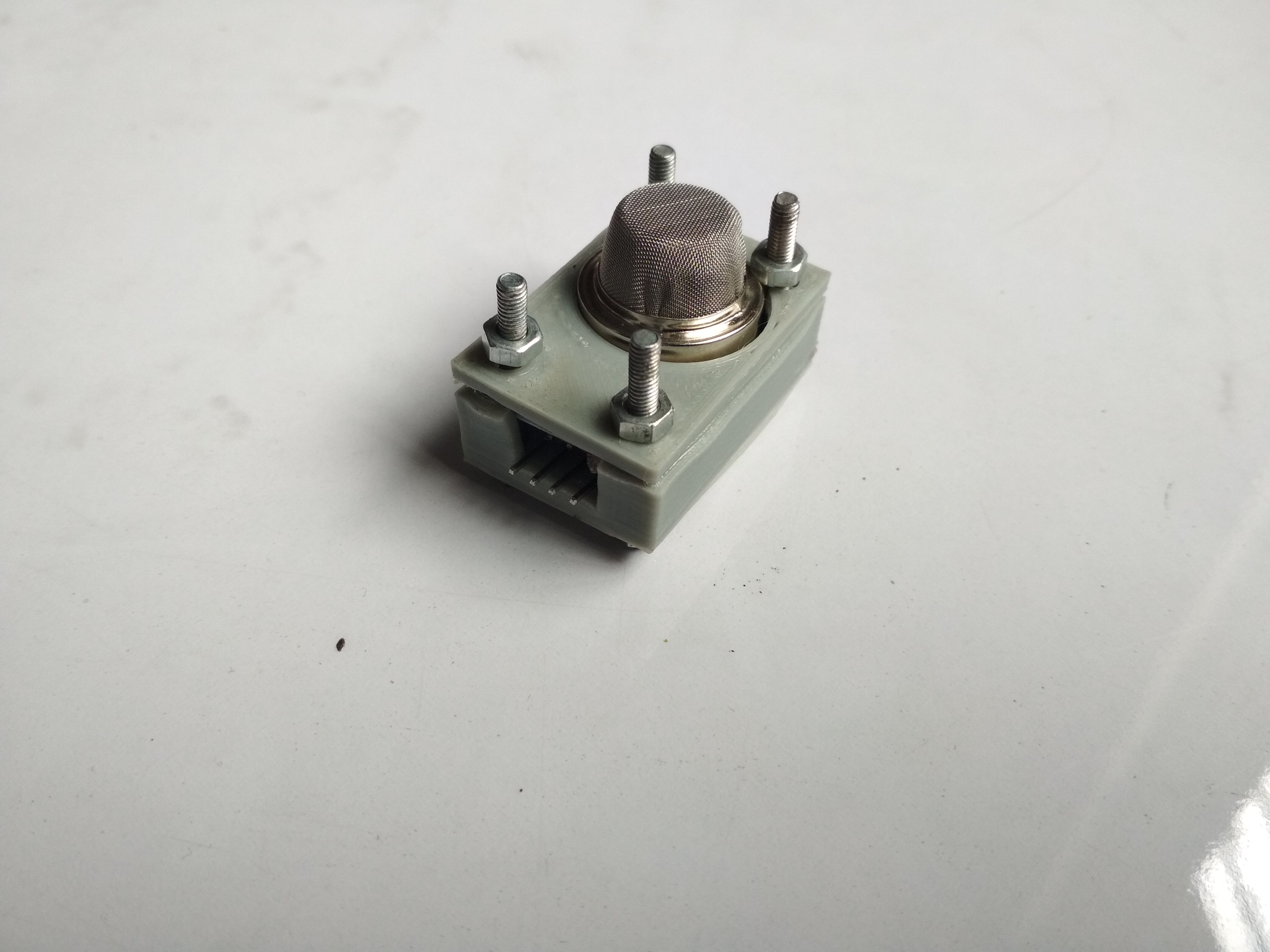
The design is exported in .stl formatt. Then open the Fractory software (CAM software for 3D printers), this design is imported and prepared for printing. The details about this process is given
in Assignment 6: 3D Scanning and Printing The printed object is here. After assembly the casing with sensor, its look like this. The following connection is made for testing: [1]Yu, X. J., Yang, M. J., Zhou, B., Wang, G. Z., Huang, Y. C., Wu, L. C., ... & Gao, X. H. (2015). Characterization of somatic mutations
in air pollution-related lung cancer. EBioMedicine, 2(6), 583-590 Go to the topThe list of components required with its specification and quantity:
Sr. No.
Name of Components
Specification
Qty.
1.
Solar Panel
20W/12V
1 Nos.
2.
Battery
7.5 AH/12V
1 Nos.
3.
Charge Controller
12V/5A Max.
1 Nos.
4.
DC Fan
5W/12V
1 Nos.
5.
ATtiny 44A Microcontroller Board
-
1 Nos.
6.
Smoke Sensor Module
MQ-2 Series
1 Nos.
7.
Realy switch
Input 5VDC/Output 10A 250VAC
1 Nos.
8.
Carbon Filter
-
1 Nos.
9.
GI Sheet for body
1 mm thickness
25 Sq, Feet.
10.
MS angle for supporting Frame
½ inch dimension
20 Feet.
11.
Cable for solar connection
1.5sq. mm
20 Feet
12.
Wire and other accessories
-
As per requirements
Input Board
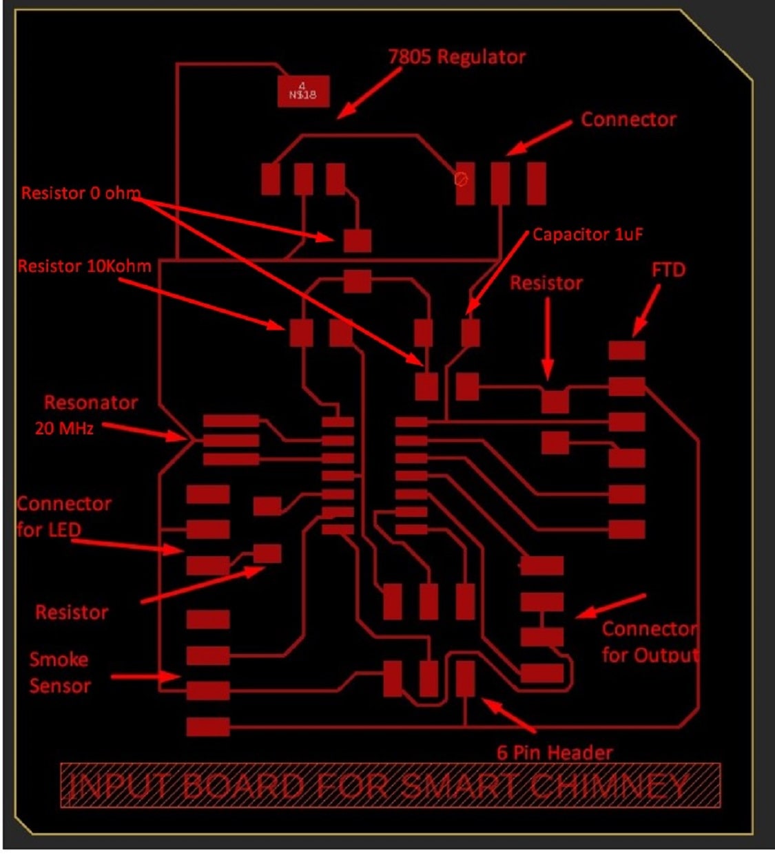
1. ATtiny 44 IC which VCC and GND pin and 12 input/output pin -01 Nos.
2. 7805 Regulator IC for to convert 9V supply of battery to 5V supply to board- 01 Nos.
3. Smoke sensor module of MQ-2 Series- 01 Nos.
4. Resonator 20M - 01 Nos.
3. 06 Pin Connector for bluetooth model - 01 Nos.
4. 6 pin header - 01 Nos.
5. Capacitor 1uF- 01 Nos.
6. Resistor (For capacitor)10 KOhm - 01 Nos.
8. Resistor (For LED) 5V/0.025A=200 Ohm But in 499 Ohm resisitor is available - 01 Nos.
9. 4 Pin connector for output- 01 Nos.
10. 4 Pin connetor for smoke sensor connection- 01 Nos.
11. 3 pin connector for input connection- 01 Nos.
12.3 pin connector for LED connection - 01 Nos.
The smoke sensor is connected by wire to the board and the final board is here.
Programming the Board
Design in Software
Packaging Box
3D Printing of Sensor Casing
Connection and Testing
The smoke sensor is attached with the microcontroller board. It is act as a input devices to the board
The relay is connected to the board is act as a output device.
The fan of kitchen is operated on Battery which is charged by solar power. The relay is connected between the fan and battery which is act as switching device to the fan.
The Rx and Tx pin of the microcontroller board is connected to Arduino Board for serial monitor. The sensor is printed on the screen of laptop by using serial monitor.
The solar pannel cable is connected to charge controller The battery cable is also connected to the charge controller. The fan is connected is connected to the charge controller.
In the series of fan, relay switch is connected.
The video is showing the connection and printing the sensor value on serial monitor.
Final Presentation
References
[2]Gao, J., Cao, C., Zhang, X., & Luo, Z. (2013). Volume-based size distribution of accumulation and coarse particles
(PM0. 1–10) from cooking fume during oil heating. Building and Environment, 59, 575-580.
[3] Poon, C., Wallace, L., & Lai, A. C. (2016). Experimental study of exposure to cooking emitted
particles under single zone and two-zone environ-ments. Building and Environment, 104, 122-130.
Fab Academy Course on Digital Fabrication by Nikhilkumar More is licensed under a Creative Commons Attribution-NonCommercial 4.0 International License.
Based on a work at http://fabacademy.org/2020/labs/vigyanashram/students/nikhilkumar-more/.
Permissions beyond the scope of this license may be available at http://fabacademy.org/2020/labs/vigyanashram/students/nikhilkumar-more//contact.html