5. Electronics production
Assignment
Individual assignment: Make an in-circuit programmer by milling and stuffing the PCB,test it, then optionally try other PCB processes.
Group assignment: Characterize the design rules for your PCB production process.
The objective was to Building the FabTinyISP which is AVR ISP programmer/board that can be produced in a fab lab using a milled PCB and readily available components. Design reference here.
Fabricating ISP
In order to build the ISP unit, I starting with the Traces:

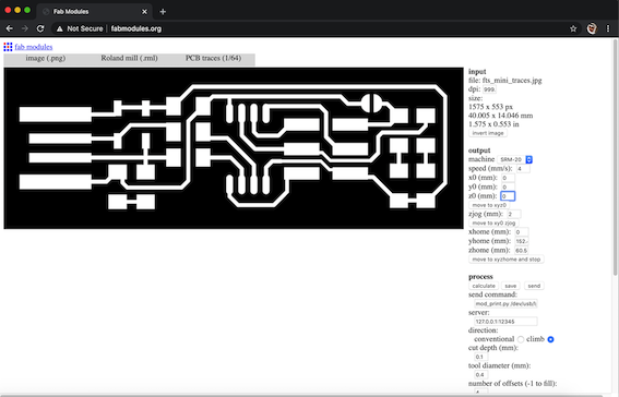
- Open Fab Modules.
- Input format: image (.png), and uploaded the traces.
- Output format: Roland mill (.rml). (the PCB milling machine name)
- Process: PCB traces (1/64).
- Set machine: SRM20 (the machine model)
-
Set:
X0 (mm): 0, Y0 (mm): 0, Z0 (mm): 0
-
Calculate
- Save (save it to USB drive)
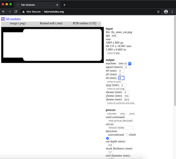
For the outline: Repeated the similar steps but used different Process: PCB outline (1/32).

Printing preparations
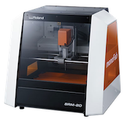
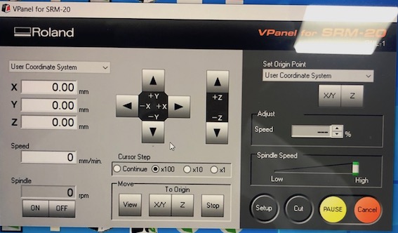
The type of machine that is used to print the circuit board at Fablab is the Roland Mill SRM-20.
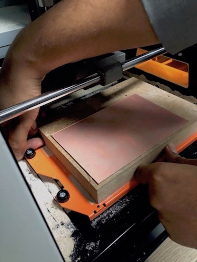
- Removed the used copper clad laminate from the MDF board and clean it.
- To attach the new FR1 copper clad laminate I used double side tape.
- Attached it and made sure that its straight and leveled.
Printing the traces
- Installed the mill bit size 1/64 SE.
- Move the mill bit to the desired starting point then click on Set origin point X/Y.
- Screw the mill bit again so it touch’s the copper laminate and click on Set origin point Z.
- Clicking on Cut I added the file that I wish to cut “fts_mini_traces.rml”.
- Pressing output starts the cut.
Printing the outline
- Milling the outline requires a mill bit size 1/32 SE.
- Clicking on Cut I added the file that I wish to cut “haribi outline.rml”.
- Pressing output starts the cut.
- Finally, remove the PCB piece with a scraper.
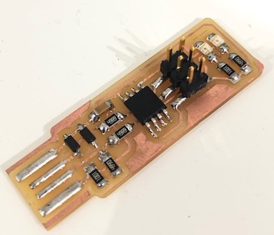
Assembling ISP
Obtain the components:
- 1x ATtiny45 or ATtiny85
- 2x 1kΩ resistors
- 2x 499Ω resistors
- 2x 49Ω resistors
- 2x 3.3v zener diodes
- 1x red LED
- 1x green LED
- 1x 100nF capacitor
- 1x 2x3 pin header
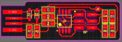
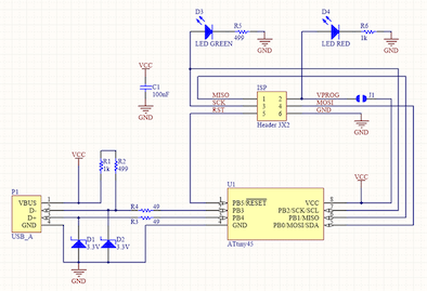
Using the schematic and board image below I soldered the parts to the PCB.
Programing ISP
To installing the software, Run the following commands in bash:
ruby -e "$(curl -fsSL https://raw.githubusercontent.com/Homebrew/install/master/install)
brew tap osx-cross/avr
brew install gcc
brew tap osx-cross/avr && brew install avr-gcc
Brew install avrdude
avr-gcc --version
make -v
Download the firmware source code and extract the zip file . Open your terminal program and cd into the source code directory.
bash comands:
cd Desktop
cd fts_firmware_bdm_v1
make
Make will build the hex file that will get programmed onto the ATtiny45.
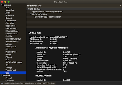
Plug the board into a USB port.
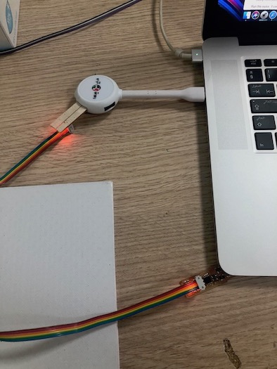
Use a USB 2.0 port “The red LED should lit up”. Connect the programmer to the ISP header on your board. To check if the ISP is plugged on mac go to Apple Menu → About this Mac → system reports → Hardware → USB
bash commands:
make flash
This will erase the target chip, and program its flash memory with the contents of the “.hex” file you built before.
make fuses
This will set up all of the fuses except the one that disables the reset pin.
make rstdisbl
This does the same thing as the make fuses command, but this time it’s going to include that reset disable bit as well.
Testing ISP
Group assignments
In the group assignment, we had the opportunity to try different material and methods for creating a PCB such as:
PCB using the Vinyl Cutter
PCB using the Fiber Laser
Using the solder mask
Using mods instead of Fabmodules to produce the files for milling
The details are found in Electronics Production Group Assignment.
Issues I Faced
- The broken mill bit: half way through printing I found out that it was not printing perfect as it spouse to do. Replaced the bit and all went back to normal.

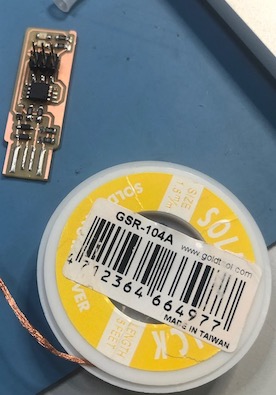
- Diodes: It’s hard to indicate the polarity of the diodes, after soldering them I had to fix one of them by removing the solder with the desoldering wire and solder it again.
-
Make flash, fuses did not work: avrdude: Can’t find programmer id “USBtinySPI”. Did all the process on mentor laptop, meanwhile a classmate found a solution Shaikha Al Mazaina Electronics Production < Programing < Step 3.
-
Had to use USB hub: USB 3.0 on Macbook pro is too fast for the ISP had to plug a USB hub.