Week 11:Output Devices
11th Week is about output devices. This week can be considered as a natural contination of Week 09: Input Devices, which was all about devices that allows us to read out data from the wrold/our environment. In this week I will use some code and parts from Week 09 to show how the readout from sensors can be showed on screens.Assigments for this week:
- individual assignment: add an output device to a microcontroller board you've designed, and program it to do something
- group assignment: measure the power consumption of an output device
Invidal Assignment
For this assigment I will start with building a circut with LCM1602 LCD 16x2 screen.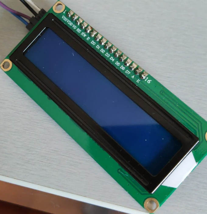
Normally connectin such screen is complicated and requires some additional components like potentiometer and resissotrs. To make the connecting easier and less messy I used LCD screen with I2C conventer soldered.
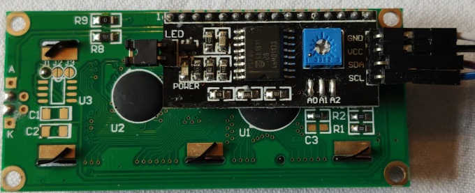
Building a connection with such conventer is simple.
To visualise how the connection will look like I used website https://www.circuito.io.
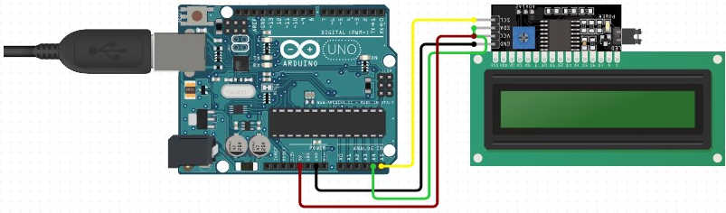
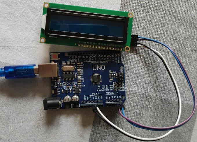
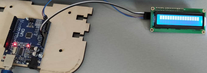
The real-life circut looks as following:
So now I have to write the code to use it 1st. But before I start writing I need to download proper library to properly use the screen. I decided to use New LiquidCrystal .
To install the library I need to place it in general folder of Arduino Libraries C:/Users/Me/Documents/Arduino/Libraries/.
Now I can take a look at LiquidCrystal_I2C.h as it is a file that I will include into my sketch. Reading that library file will give me important informations about using in at its full potential.
Lets start code writing. I asked the professional for aid.

After 15-20 minutes the code looks as following:
#includeAfter I uploaded the code into the board nothing happened... or rather this happened:// standard lib for Arduino projects like this #include // lib for I2C for LCD that I downloaded and installed into arduino library LiquidCrystal_I2C lcd(0x27, 2, 1, 0, 4, 5, 6, 7, 3, POSITIVE); // Setting an address of I2C for 0x27 void setup() { lcd.begin(16,2); // Iinicialisation of LCD 2x16 lcd.backlight(); // Turning on the backlight of the screen lcd.setCursor(0,0); // Seting a position for cursors on 1st top line, which is basically a place where it will start writing the text lcd.print("Hi Fabacademy!"); // Writing text on screen delay(500); lcd.setCursor(0,1); // Seting cursors on second line lcd.print("2020"); // Writing text on screen } void loop() { // nothing here cuz it is just a test }
To find the solution of the problem I decided to make a list of the possible bugs:
- Code
- Connection
- Arduino itself
- Connection wires
For 1st try was the connection, I checked online datasheets for the LCM1602 module with i2c conventer and it turned out to be OK.
As 2nd I decided to check on new arduino but problem remained.
3rd try goes to connection wires, I made simple LED circut to test if the wires are OK and test came out possitive for all wires.
As a 4th and last try I checked again very slowly the code. It looked OK.
I have spend few hours looking and diging for the problem.
After this time I realised that I might have wrong I2C address. To check this I found on Arduino website a code that checks the connected I2C device address.
I2C Scanner
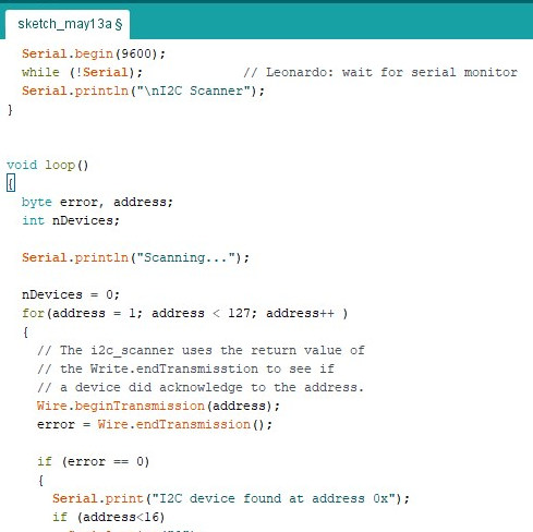
Using this I2C Scanner worked perfectly after a second I knew the proper address for my i2c conventer.
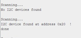
After I changed the line that is responsible for I2C address:
Before:
LiquidCrystal_I2C lcd(0x27, 2, 1, 0, 4, 5, 6, 7, 3, POSITIVE);After:
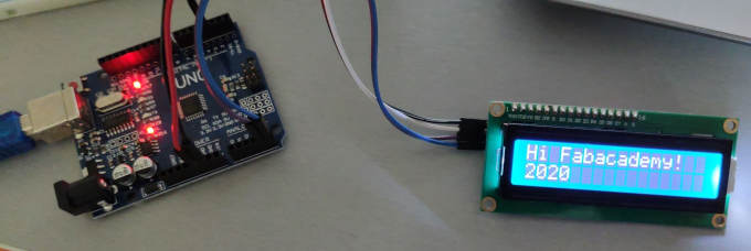
LiquidCrystal_I2C lcd(0x20, 2, 1, 0, 4, 5, 6, 7, 3, POSITIVE);I uploaded the code again and the effect was as it was expected to be:
Adding DHT11 Sensor
To make the circut more intresting I decided to add a DHT11 sensor to make a readout of temperature and humidity visible on the LCD screen. I will use knowledge from the Input Devices week and use the scheme of the circut. I will also add a button to the circut.The circut will work in following scheme:
1. The setup will print "%RH" and "*C" on screen in two separte lines.
2. The void loop will wait for user to the button.
3. After the button is pressed the DHT11 sensor will make a readout.
4. The readout will be added to the coresponding lines on the screen.
To make the code I merged the code from before with the code from week 09 and also added button state check feature. So the code looks as following:
#include "DHT.h" //Including the sensor library #includeOperation of the circut:// standard lib for Arduino projects like this #include // lib for I2C for LCD that I downloaded and installed into arduino library #define DHT11_PIN 6 // defining the physical sensor - telling the board on which PIN the sensor data in supplied DHT dht; // declaration needed for DHT library const int buttonPin = 3; //Pin for the button LiquidCrystal_I2C lcd(0x20, 2, 1, 0, 4, 5, 6, 7, 3, POSITIVE); // Setting an address of I2C for 0x20 void setup() //setup void in which we state things that we want to declare once for whole code operation like pins etc. { pinMode(buttonPin, INPUT); //setting the input PIN Serial.begin(9600); // declaration of badurate need to communicate with board on serial monitor dht.setup(DHT11_PIN); // declaration of type of the sensor applied for library purpose lcd.begin(16,2); // Inicialisation of LCD 2x16 lcd.backlight(); // Turning the screen backligh on lcd.setCursor(0,0); // Seting a position for cursors on 1st top line, which is basically a place where it will start writing the text lcd.print("%RH="); // Printing on the screen delay(500); lcd.setCursor(0,1); // Setting the cursor on 2nd line lcd.print("*C"); // Printing on the screen } void loop() // loop void is a section that is repeated continuously { if (digitalRead(buttonPin) == HIGH) //checking the state of the button { int humm = dht.getHumidity(); // using command supplied by library to read value of humidity and signing it into a int valuable lcd.setCursor(4,0); lcd.print(humm); int temp = dht.getTemperature(); // using command supplied by library to read value of temperature and signing it into a int valuable lcd.setCursor(3,1); lcd.print(temp); delay(1000); } delay(500); }
Group Assignment
Task in this week group assigment is to measure a power consuption of an output device. We will measure a power consuption on Servo and LCD 16x2 screen pluged on I2C.Since we do not have access to our lab we will pefrome the test in home using Arduino.
LCD Screen Test
1st thing to measure is Volate. We connected the multimeter in parallel connection and got read out of 4.8V.2nd thing we measured are Amps. This time it is a bit more tricky. It is important to connect it in series so the current passes trough the multimeter.
We got the read out from 18.8 to 23 mA.
So using the formula: P = V * I we got:
(We changed mA to A)
Pmin = 4.8 * 0.0188 = 0.09024W
Pmax = 4.8 * 0.023 = 0.1104WServo Test
1st thing to measure is Volate. We connected the multimeter in parallel connection and got read out of around 4.7V.2nd thing we measured are Amps. In the same way as in previous example.
We got the read out from 21.1 to 75 mA.
So using the formula: P = V * I we got:
(We changed mA to A)
Pmin = 4.7 * 0.0211 = 0.09917W
Pmax = 4.7 * 0.075 = 0.3725W