Week 06: Electronics Design
Group assigment:
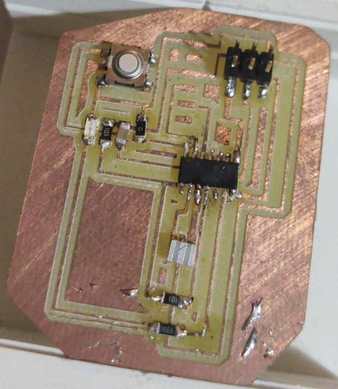
- use the test equipment in your lab to observe the operation of a microcontroller circuit board.
Invidual assigment:
- redraw an echo hello-world board
- add (at least) a button and LED (with current-limiting resistor) check the design rules
- make it
- test it extra credit: simulate its operation Google drive with all files
Group Assignment
Use the test equipment in your lab to observe the operation of a microcontroller circuit board.Link for group assigment on Maciej Naskręt Page:Week 06 Group Assigment
Invidual Assignment
Our invidual assigment in this week was to redraw PCB board in software designed for this. I choose Eagle, it was just a visual choice so I do not know what I am getting into.
So let's start! First of all I downloaded the software from website, it is free so it is available for everyone. Eagle Download
After installing the software and being too cocky with my knowladge and skills I got hit in the face by the Eagle... So obediently I have steped back and looked on Eagle tutorial.
I started everything with downloading Eagle FabAcademy libraries .
Now I can finally launch Eagle and start designing! First step is making a new project. After that I need to check what components are included into Hello FTDI.44 board.
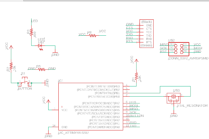
So the components are following:
* Hearth of the board: ATtiny 44 microcontroller
* FTDI Connector
* 6-pin ISP header
* 10k Ohms resistor
* 449 Ohms resistor
* 20Mhz resonator
* 1uF Capacitors
* LED
* Switch button
Now I can start making scheme.
After making the scheme and connecting all components by "invisible wires" it is time to prepare look of real board.
First thing to do is to transfer all components to the board area and placing them in some logical pattern.
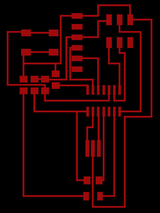
It took me 5-6 tries to make it work. I am still not happy with the look so I am sure I will make better , improved, version soon.
Next thing is to create the routing. I exported the traces into a PNG file. Edited it in GIMP to change the traces into white.
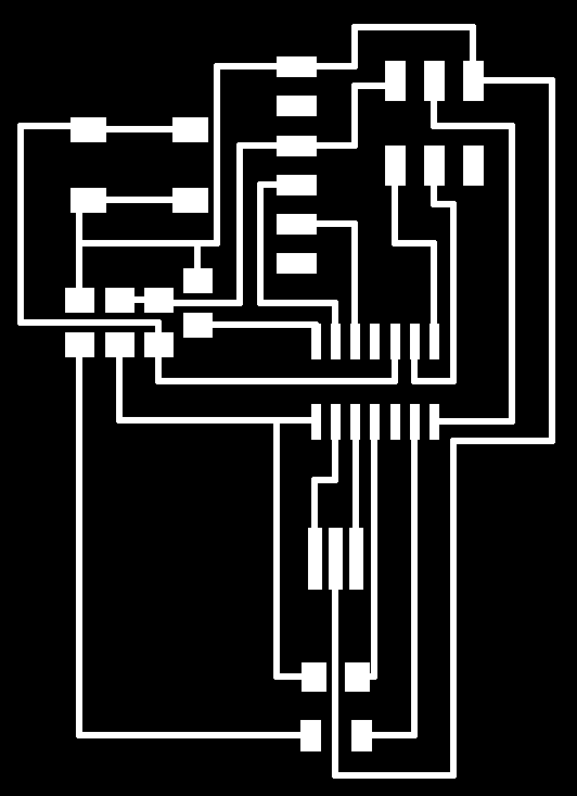
Also added the cut out trace.

Now I have to go to use mods. http://mods.cba.mit.edu
Set it for 2D milling mode from PNG file.
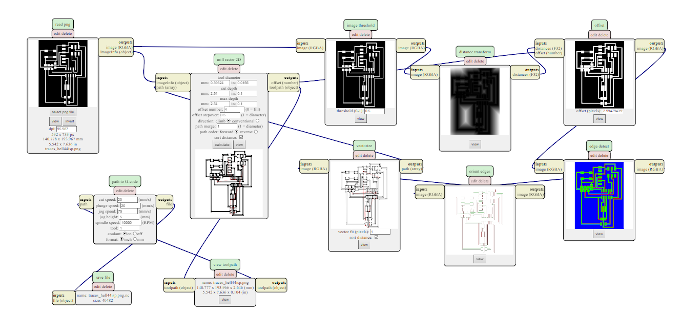
The same happened with cutout trace. After having both traces, now I can transfer everthing into CNC Miller control software.
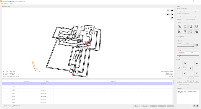
All is left is to mill it and solder it.. only...
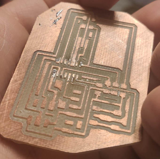
Milled board:
Now I need to solder the components.
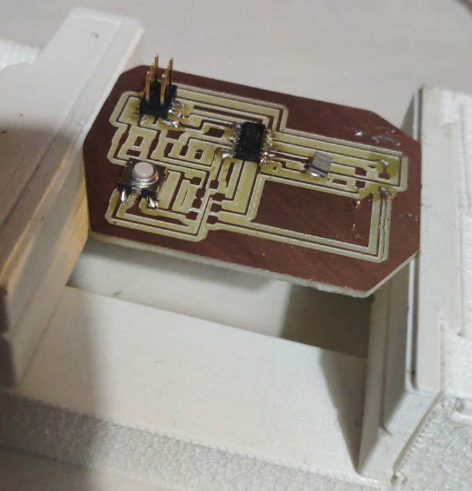
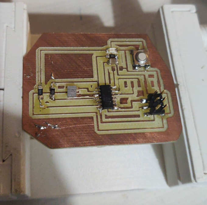
In my oryginal design I had FTDI added but I decided that I do not need a communication with simple on-off LED switch.
Tinkercad Simulation and Arduino powered substitute
Since it was impossible for me to finish the board physically I have to use arduino and Tinkercad Circuts as a substitute for now. As soon as I come back to the FabLab I will add proper solution for assigment given.
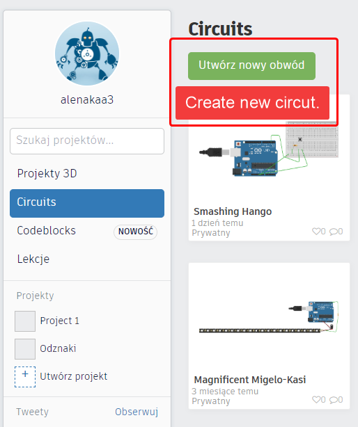
I started this proces by entering the Tinkercad webpage. Loged into my account and started new project on Tinkercad Circuts workflow.
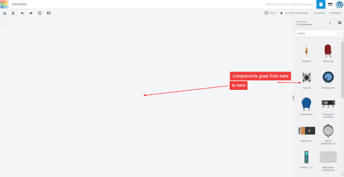
Now I need to add components from the righr side of the screen to the center where the build area is.
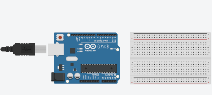
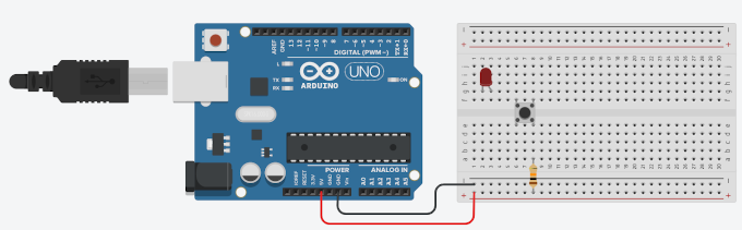
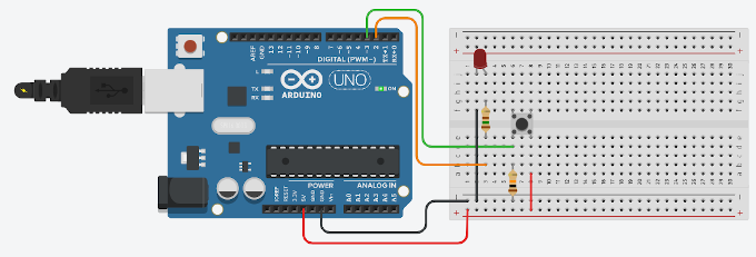
The first thing I made was to add an Arduino board that I will work on and a breadboard to place smaller components.
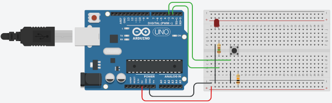
Now I have added a RED LED , tact switch as a button and 10K Ohm ressistor. Then I connected 5V as a red wire and GND as a black wire to the board.
Then I added more wires to connect the LED with GND, supplied from the bottom of the board, as the katode and OUTPUT Pin 2 from Arduino as the anode. There is also one green wire that is connected with INPUT pin 3 of the Arduino board which detects the state of the button.
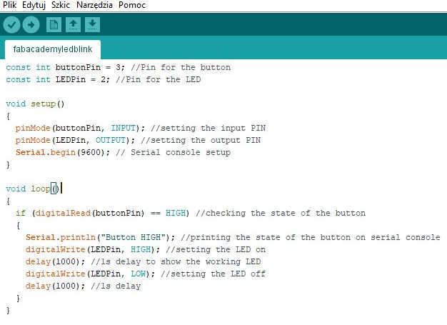
Now it is time to write the code. To make it I need to enter the code writing mode. It is in the top under "Kod" (Polish for "Code"). 1st visibile workflow is for blocks of code which is good for beginning users in programing. But it can be changed into standard typing method.
The code for blinking the LED is following:
const int buttonPin = 3; //Pin for the button
So now I can test if the code is working!
const int LEDPin = 2; //Pin for the LED
void setup()
{
pinMode(buttonPin, INPUT); //setting the input PIN
pinMode(LEDPin, OUTPUT); //setting the output PIN
Serial.begin(9600); // Serial console setup
}
void loop()
{
if (digitalRead(buttonPin) == HIGH) //checking the state of the button
{
Serial.println("Button HIGH"); //printing the state of the button on serial console
digitalWrite(LEDPin, HIGH); //setting the LED on
delay(1000); //1s delay to show the working LED
digitalWrite(LEDPin, LOW); //setting the LED off
delay(1000); //1s delay
}
}
Unfortunately something went wrong and the circut was not working. After few minutes of inspecting the board I found out that I have putted the 10k Ohm ressistor before the switch.
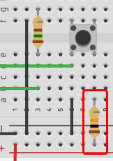
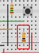
On the left wrongly made circut and on the right corrected version.
After this change the circut looks like following:
 And now it works :)
After I know it worked on virtual enviroment I decided to make it real.
Here is a photo of assambled circut:
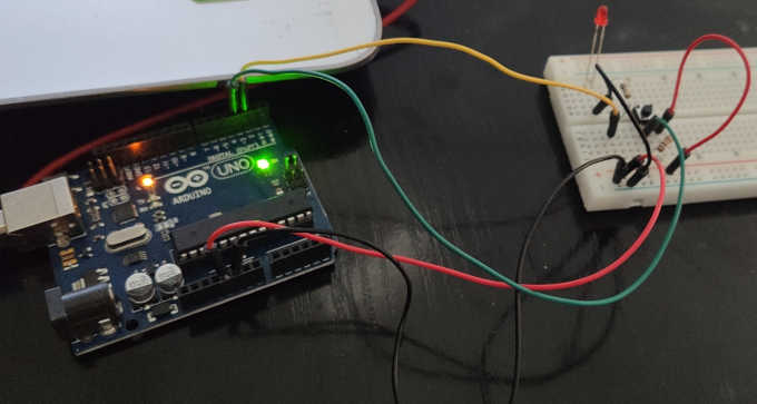
After assembling I connected the Arduino Uno board into the PC and using Arduino IDE software I transfered the sketch (writen program) to the board.
And here is a video of working circut.