Week_6 - Electronics design
Assigment
- group assignment:
- use the test equipment in your lab to observe the operation of a microcontroller circuit board
- individual assignment:
- redraw an echo hello-world board
- add (at least) a button and LED (with current-limiting resistor)
- check the design rules, make it, and test it
- extra credit: simulate its operation
Group Assignment
use the test equipment in your lab to observe the operation of a microcontroller circuit boardUse the test equipment in your lab to observe the operation of a microcontroller circuit board (in minimum, check operating voltage on the board with multimeter or voltmeter and use oscilloscope to check noise of operating voltage and interpret a data signal) Equipment used in testings:
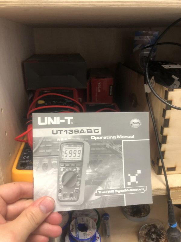
Multimetr
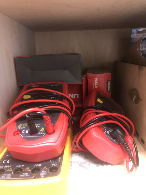
"A multimeter or a multitester, also known as a VOM (volt-ohm-milliammeter), is an electronic measuring instrument that combines several measurement functions in one unit. A typical multimeter can measure voltage, current, and resistance. Analog multimeters use a microammeter with a moving pointer to display readings."
Wikipedia
The best way to start working with a multimeter is first of all to read the manual, which is always available with multimeters in our lab.
Oscilloscope
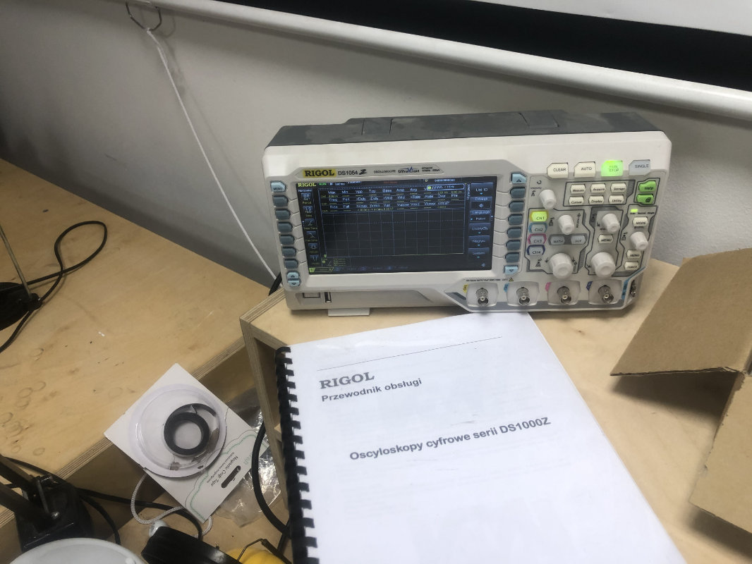
An oscilloscope is a laboratory instrument commonly used to display and analyze the waveform of electronic signals. In effect, the device draws a graph of the instantaneous signal voltage as a function of time.
we have in our fablab :
Rigol DS1054
link to manual
link to software manual
Laboratory Power Supply
The power supply first uses a rectifier to convert house alternating current (AC) into direct current (DC), the only type that common instruments and devices use. It then adjusts the current and/or voltage upward or downward to meet the needs of the instrument.
Using equipment
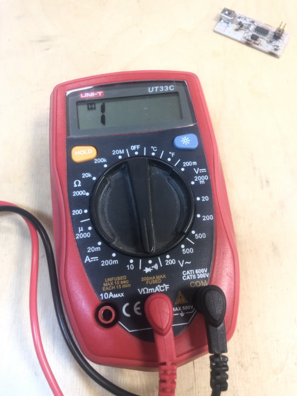
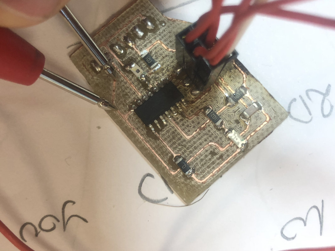
MultimeterThe most common task for the multimeter during our work with pcb boards so far was to use it to check the continuity of the circuit and ( buzzer) and check the solders/resistance. It is also very important to check if we have connected FTDI pins to Attina microcontroller.
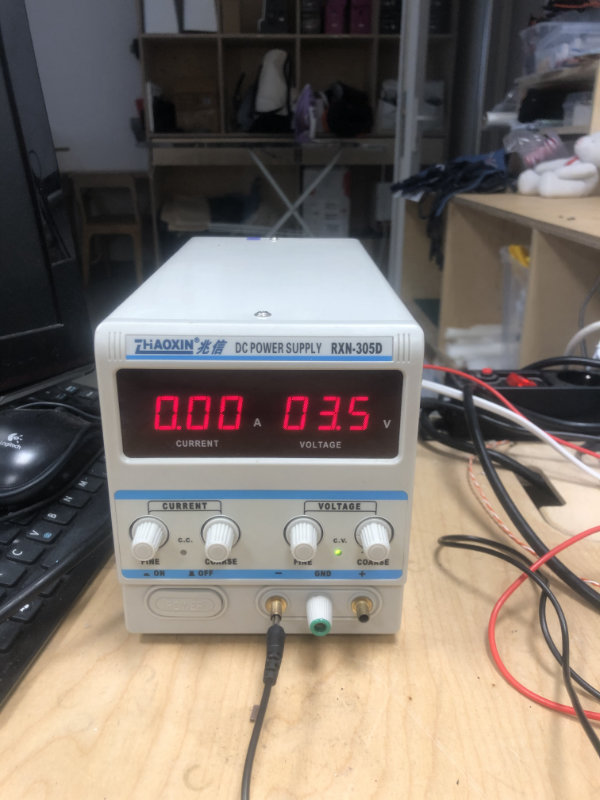
Power supply
Power supplier is the best tool to give precise power to the machine and to test what changes will be brought about by increasing or decreasing the current and voltage. All changes are made using two knobs, one for voltage and one for current. It is a very simple tool which allows us to quickly test and check how our board works under different current conditions. For Tiny boards the voltage is 5v. The board can be powered by FTDI by connecting it to the appropriate pins ( previously it can be checked with a multimeter).
After connecting 5v, you will see how much current the board is consuming. This is very important information to determine the battery life of the device.
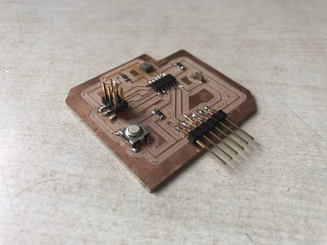
individual assignment:
Redraw an echo hello-world board
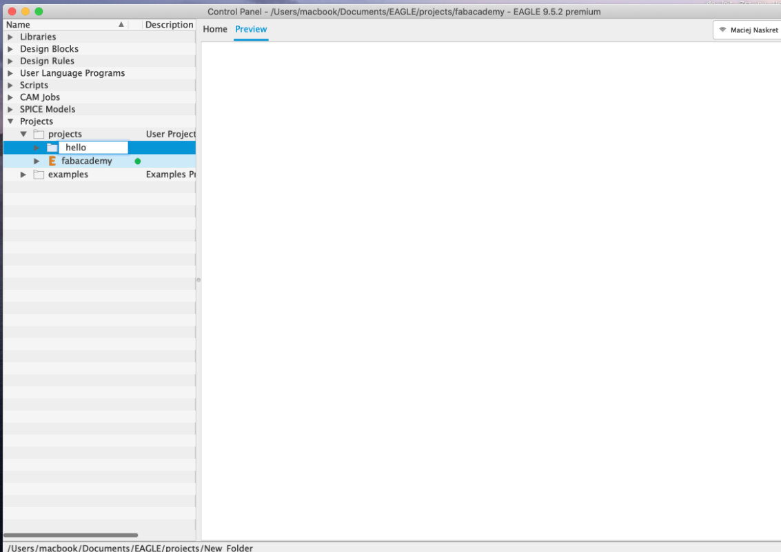
For the first time in my life I designed pcb boards so I had to learn the program and the elements of the electronic circuit. To learn the program I used a very good and simple tutorial available on Fab Academy website. To remind the basics of electronics I used instructables Electronic classes . Eagel turned out to be a very logical and easy to use program, it was enough to logically separate schematics and boards and learn basic commands.
Schematic
and it's always good to know where are the buttons in ui of the software. We always start by creating a design and a schematic of the board.
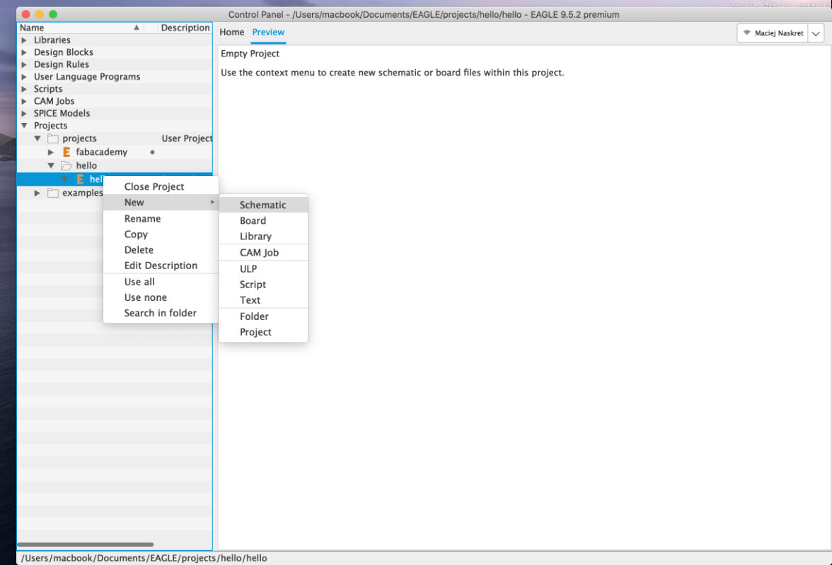
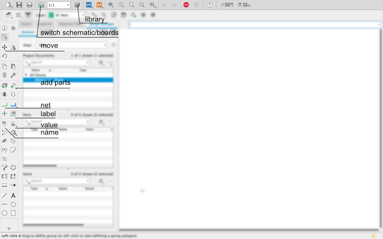
eagle UI
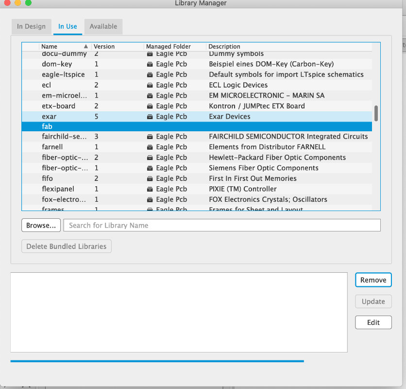
You always have to check if we have an imported library of plots in our libraries, which can be downloaded from here)
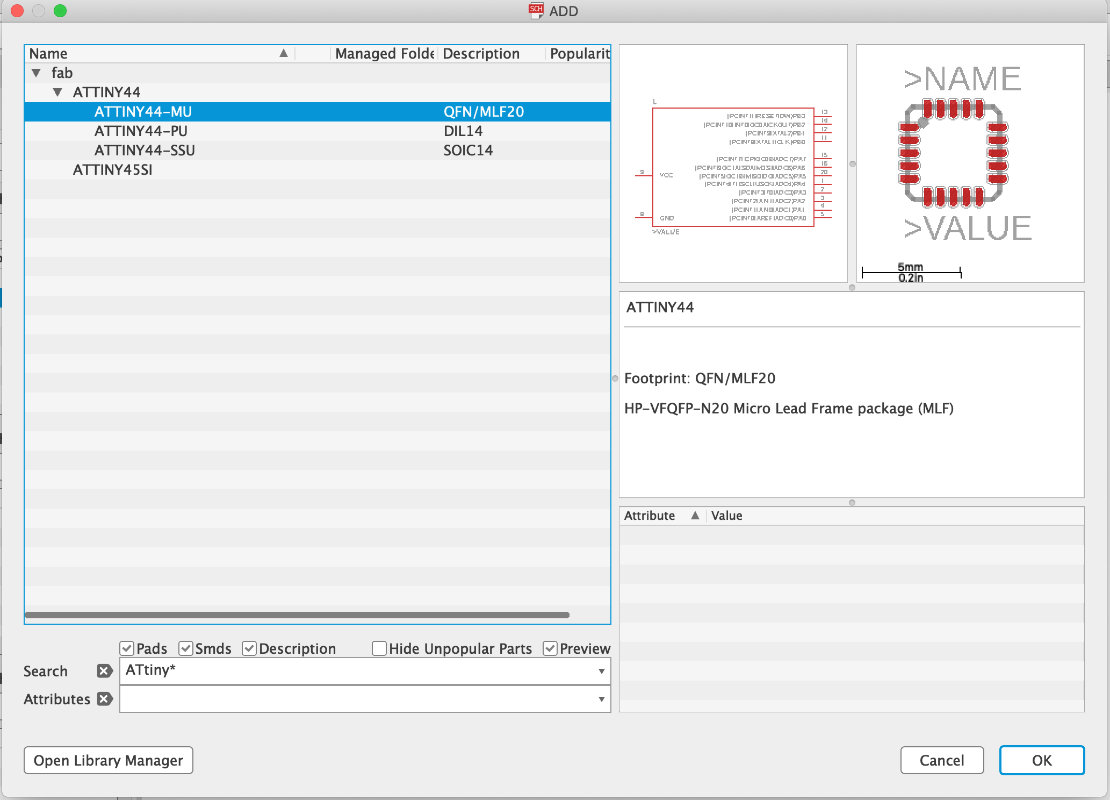
After adding the library we search and add all necessary elements to the layout. We combine all the parts by giving the net names.
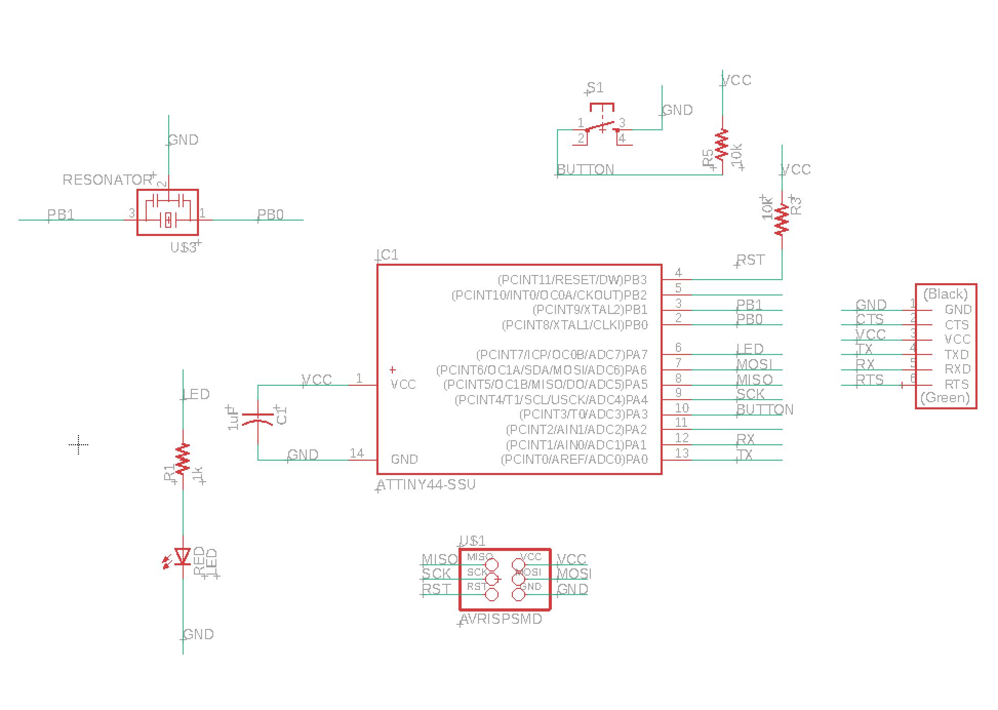
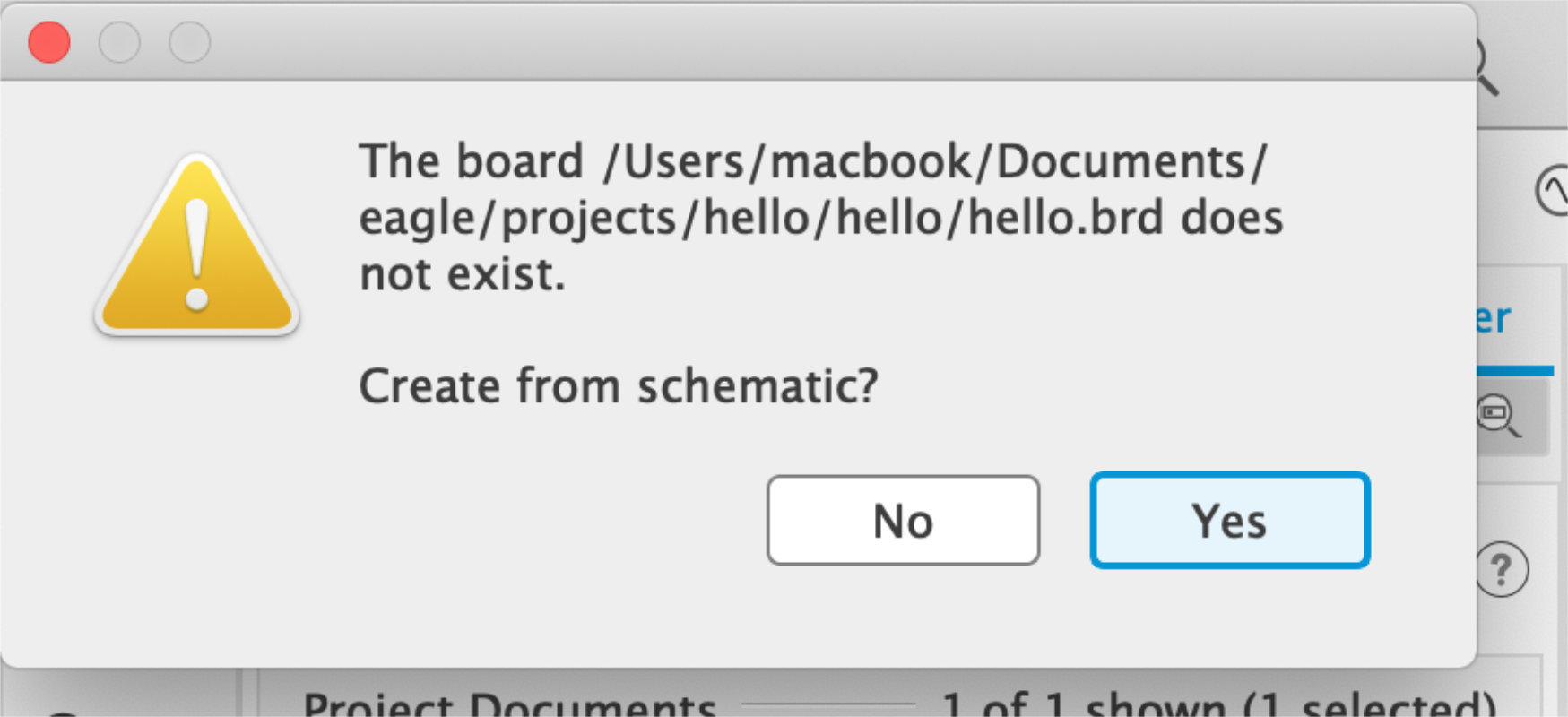
after i created the schamet its time to switch our view to board with the button on the top left (shown on previous screen)
Board
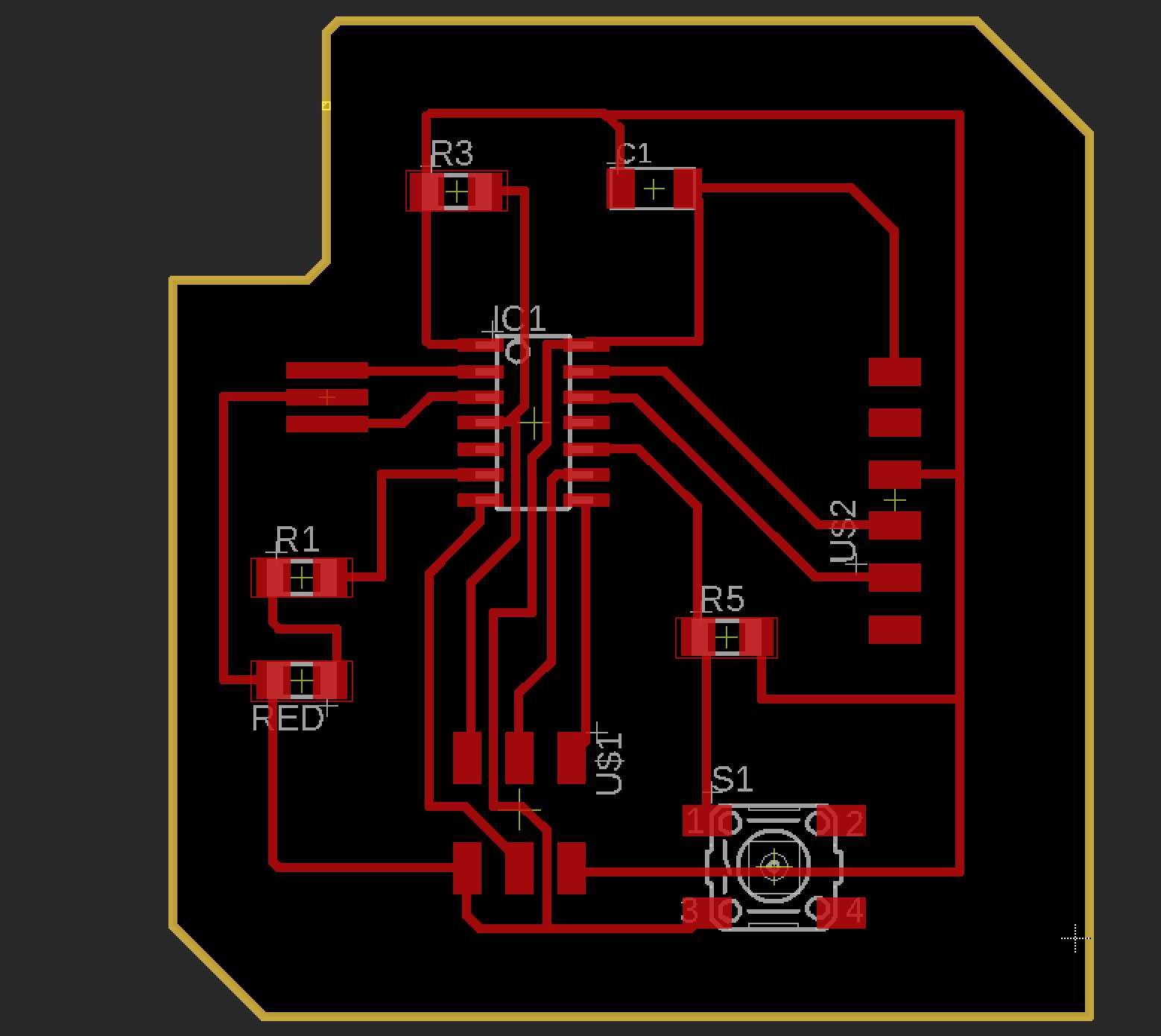 Routing
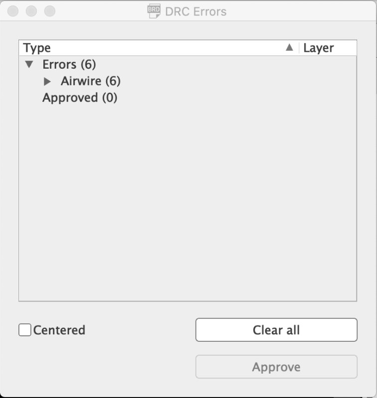 DRC check
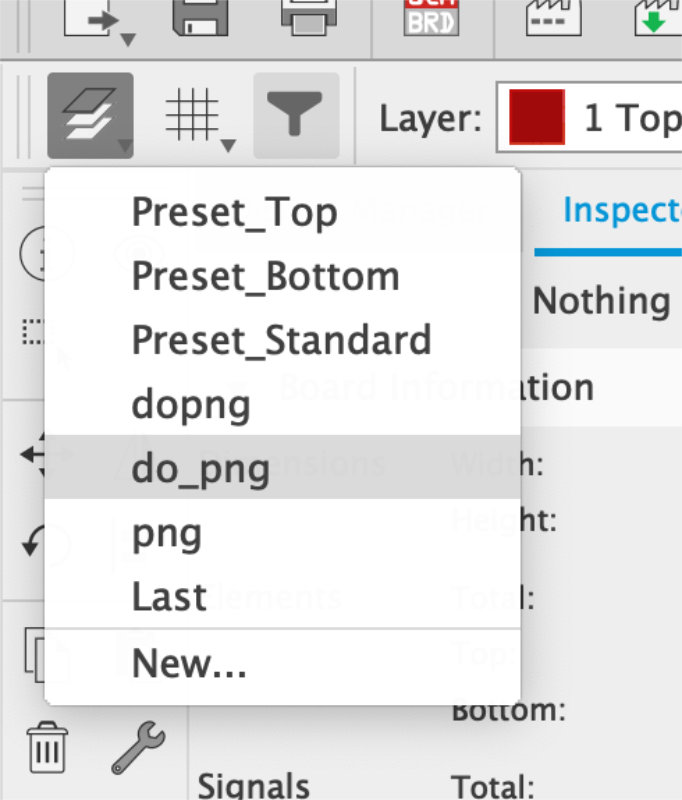 using presets to export routes and pads only
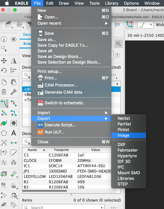 File=>Export=>Image
 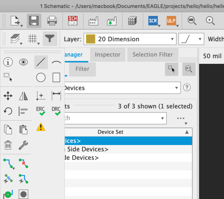 After exporting routes and pads I creat the new layer with border of the board. I creat the new lines on layer dimension (because i didnt use this layer into the design)
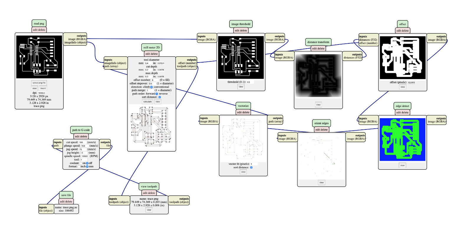 Using Fab Moduls i creat the path for a cnc machine
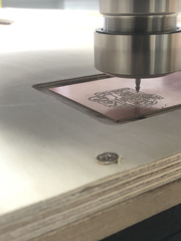
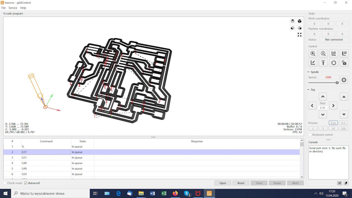 Prepered files into the cnc software