
Final Project
First Skatches
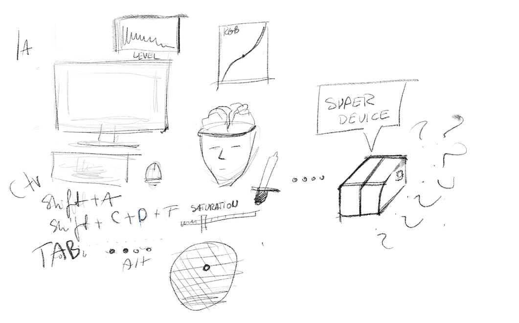
Let's start with the fact that I have been working on photography and video processing semi-professionally and amateurishly for over 15 years. Quite a lot. I have used a lot of software and unfortunately I always have the same problem with all sliders and samplers, that you have to be very precise and have a lot of patience to choose the values exactly how you want them. Some time ago I had the pleasure of working on professional equipment for thousands of dollars to edit video with real sliders, buttons, knobs and so on. Feelings from work were incredibly better. So as always, I started looking for alternative options. I found on the Internet the idea of connecting midi controllers and then mapping the keys with the program. Unfortunately most people work with midi controllers for music so they are usually big and uncomfortable and it's hard to put them in a backpack to go to a client or another city for sessions and take pictures quickly and conveniently. Below I present my thoughts on this project and some initial sketches and ideas.
Idea
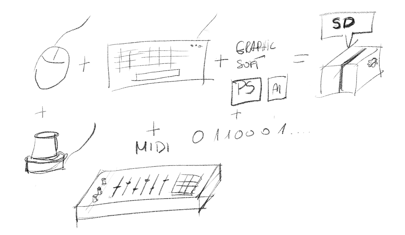
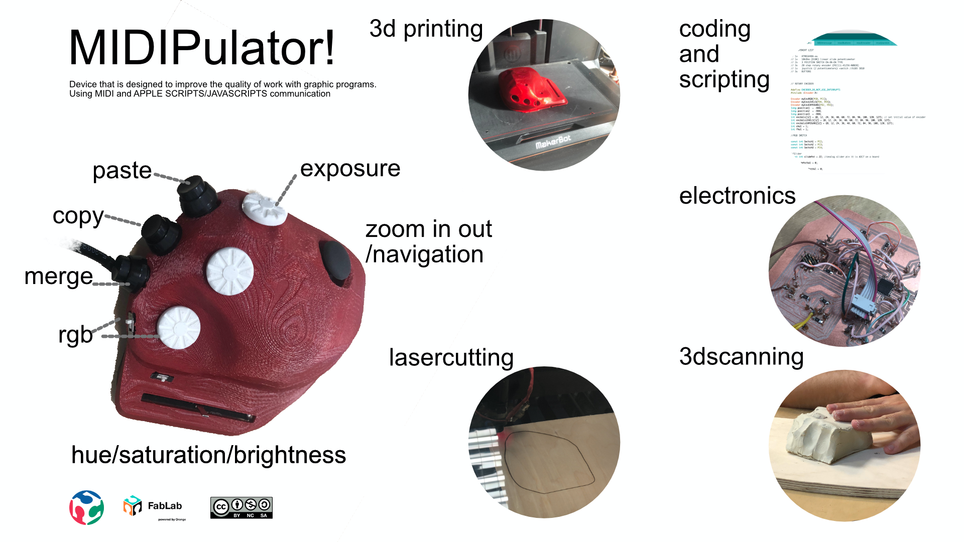
My project is a manipulator for graphics programs aimed at helping all those who have already had enough of millions of keyboard shortcuts and clicks. The basis of the manipulator is midi communication hence the name MIDIPULATOR! I chose this way of communication because I knew that there are many applications that use midi as a simple system for communication. Moreover, I was inspired by the videos on yt, where people used midi controllers to edit photos. Unfortunately such a midi manipulator is quite clumsy and at best it requires a space as much as a keyboard. So I came up with the idea that I will communicate using midi. Then I had to find out how such communication looks like or what midi is:
MIDI
The MIDI language is used to transmit real time information for the playback of a piece of music.
"Real time" means that each message is sent exactly at the moment it must be interpreted by the target synthesizer (which can be a hardware synthesizer or software synthesizer).
Various messages are defined to transmit the information needed to perform the playback of music. The important point is that the MIDI language does not define the sound itself, but only the sequence of instructions to create the sound in the target synthesizer.
The MIDI messages are sent as a time sequence of one or more bytes (8 bits). The first byte is a STATUS byte, often followed by DATA byteswith additional parameters. A STATUS byte has bit 7 set to 1 and aDATA byte has bit 7 set to 0.
Thanks to this description from MIDI Association I started to understand what this whole midi is about.
Capture the sginal
 I used Controllermate and Hairless midi serial to take over the signal.
Controllermate
ControllerMate for Mac gives you the ability to customize various devices, including the keyboard and mouse, joystick, gamepads, and more, for use with your computer. With a bit of experimenting, you can create all kinds of automated processes to streamline tasks.
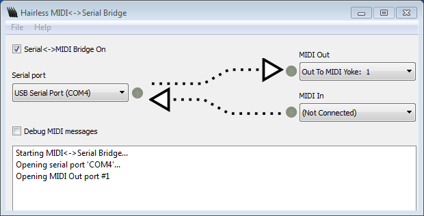
Hairless MIDI<->Serial Bridge
Hairless MIDI<->Serial Bridge is the easiest way to connect serial devices (like Arduinos) to send and receive MIDI signals. 100% Free Software. For Mac OS X, Windows & Linux.
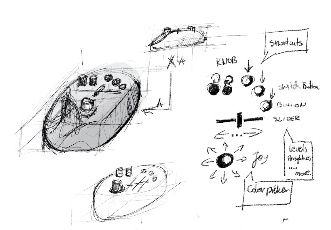
Componenets
Then I selected the components I'd need and the functions I'd like to use in... and here's the problem, because not all programs use scripts. But that's in a minute. First the hardware.
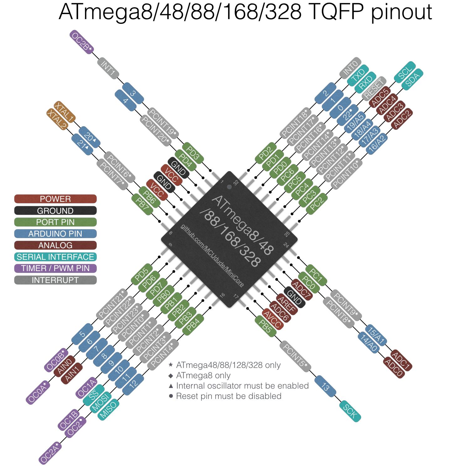
Because of the large number of pins I used atmega48a-and it was my first contact with this microchip so it took me a while to get to know its capabilities but the most important thing was the right amount of digital pins and analogs and UART support.
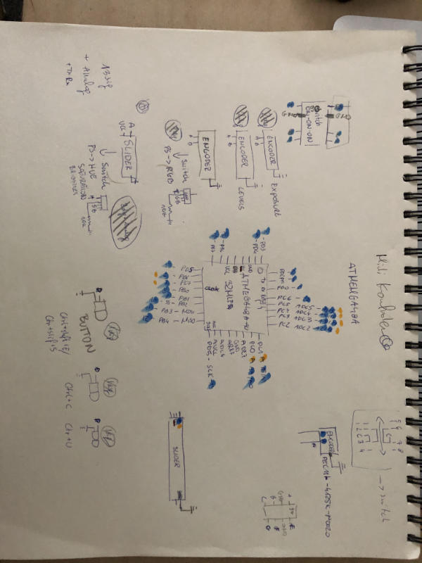
Once I created the radmap, I started assigning specific devices to the individual pins and checking if I had enough anologists. below is a diagram of what it looked like.
Proof of Concept
I knew it would work, but I had to see if I could find an old midi controller, which surprasingly had an usb. Using the controllermate I started to add specific buttons and assign them functionality and here comes APPLE SCRIPT, which, as I found out later, could be replaced by java script, but that's already with version 0.2 :)
Apple Script
AppleScript is a scripting language developed by Apple to help people automate their work processes on the Mac operating system. It accomplishes this by exposing every element of the system's applications as an object in an extremely simple, English-like language. AppleScript is to the Mac OS as JavaScript is to browsers.
And here we go back to the scripts and to the program I chose as my test object, and that is photoshop to the total at the moment only he has a decent documentation to handle this language:
https://www.adobe.com/content/dam/acom/en/devnet/photoshop/scripting/Photoshop-CS6-AppleScript-Ref.pdf
below are a few examples that I've used and edited for myself:
cmd+page up+shitf
cmd+page dwon +shitf
cmd=55
page up= 116
page dwon= 121
tell application "System Events" to key code 116 using {command down, shift down}

tell application "System Events" to key code 121 using {command down, shift down}
cmd+page up+shitf
cmd+page dwon +shitf
cmd=55
page up= 116
page dwon= 121
tell application "System Events" to key code 116 using {option down, shift down}

tell application "System Events" to key code 121 using {option down, shift down}
cmd+ +
smd+ -
+ = 69
- = 78
		tell application "System Events" to key code 69 using {option down, shift down}

tell application "System Events" to key code 78 using {option down, shift down}
tell application "Adobe Photoshop CS6"
    adjust current layer of the current document using brightness and contrast ¬
   	 with options {class:brightness and contrast, brightness level:10, contrast level:0} ¬

end tell
Coding
For the sake of comfort of work I chose Wire language, which is commonly known as Arduino with plugin/plates from mini core which gave me the possibility of programming from arduino ide, ATmega48 . If it's about the code itself, it's divided into tabs, which correspond to individual programs, and everything to make your work easier and keep the code in clear is full of comments, so everyone should understand what it's about.
The main task of this code was to read the positions and remember them.
The rest of the main program is in files:
// COMPONENT LIST

// 1x   ATMEGA48A-au
// 1x   10kOhm (B10K) linear slide potentiometer
// 2x   3 POSITION SWITCH ON-ON-ON TYPE
// 3x   20 step rotary encoder (PEC11L-4125K-N0020)
// 1x   joystick (2 potentiometers) +switch //b103 3810
// 3x   BUTTONS


// ROTARY ENCODER

#define ENCODER_DO_NOT_USE_INTERRUPTS
#include

Encoder myEncRGB(PC0, PC1);
Encoder myEncLEVELS(PD4, PD5);
Encoder myEncEXPOSURE(PD2, PD3);
long position1  = -999;
long position2  = -999;
long position3  = -999;
int encVals[12] = {0, 12, 24, 36, 48, 60, 72, 84, 96, 108, 120, 127}; // set initial value of encoder to mid range of 0-127
int encValsLEVELS[12] = {0, 12, 24, 36, 48, 60, 72, 84, 96, 108, 120, 127};
int encValsEXPOSURE[12] = {0, 12, 24, 36, 48, 60, 72, 84, 96, 108, 120, 127};
int eVal = 1;
int fVal = 1;

//RGB SWITCH

const int Switch1 = PC2;
const int Switch2 = PC3;
const int Switch3 = PC4;

//Slider
const int slidePot = 22; //analog slider pin it is ADC7 on a board

int slidePotVal = 0;

int lastSlidePotVal = 0;


//Hue and saturation switch

const int Switch4 = PB4;
const int Switch5 = PB3;
const int Switch6 = PB5;


int cVal = 1;
int hVal = 1;

// JOYSTICK

const int joyX = PC5;  // joystick pins
const int joyY = PC4;
const int joySw = PB6; //zoom button

int joyXval = 0;
int joyYval = 0;
int lastJoyXval = 0;
int lastJoyYval = 0;

//Buttons
const int buttonCopy = PB0 ;
const int buttonPaste = PB1 ;
const int buttonMerge = PD6 ;


void setup() {

  Serial.begin(9600); // enable serial communication

  pinMode(Switch1, INPUT);
  pinMode(Switch2, INPUT);
  pinMode(Switch3, INPUT);
  pinMode(Switch4, INPUT);
  pinMode(Switch5, INPUT);
  pinMode(Switch6, INPUT);

}


void loop() {

  readSwitch();    // read 3 POINT on-on-on switch RGB
  readSwitch1();    // read 3 POINT on-on-on switch hue saturation
  readEncoder();      // read roraty encoders
  readJoystick();     // read joystick + switch
  readSlider();       // read Huea/saturation Slider
  readButtons();      //read buttons

}
PCB
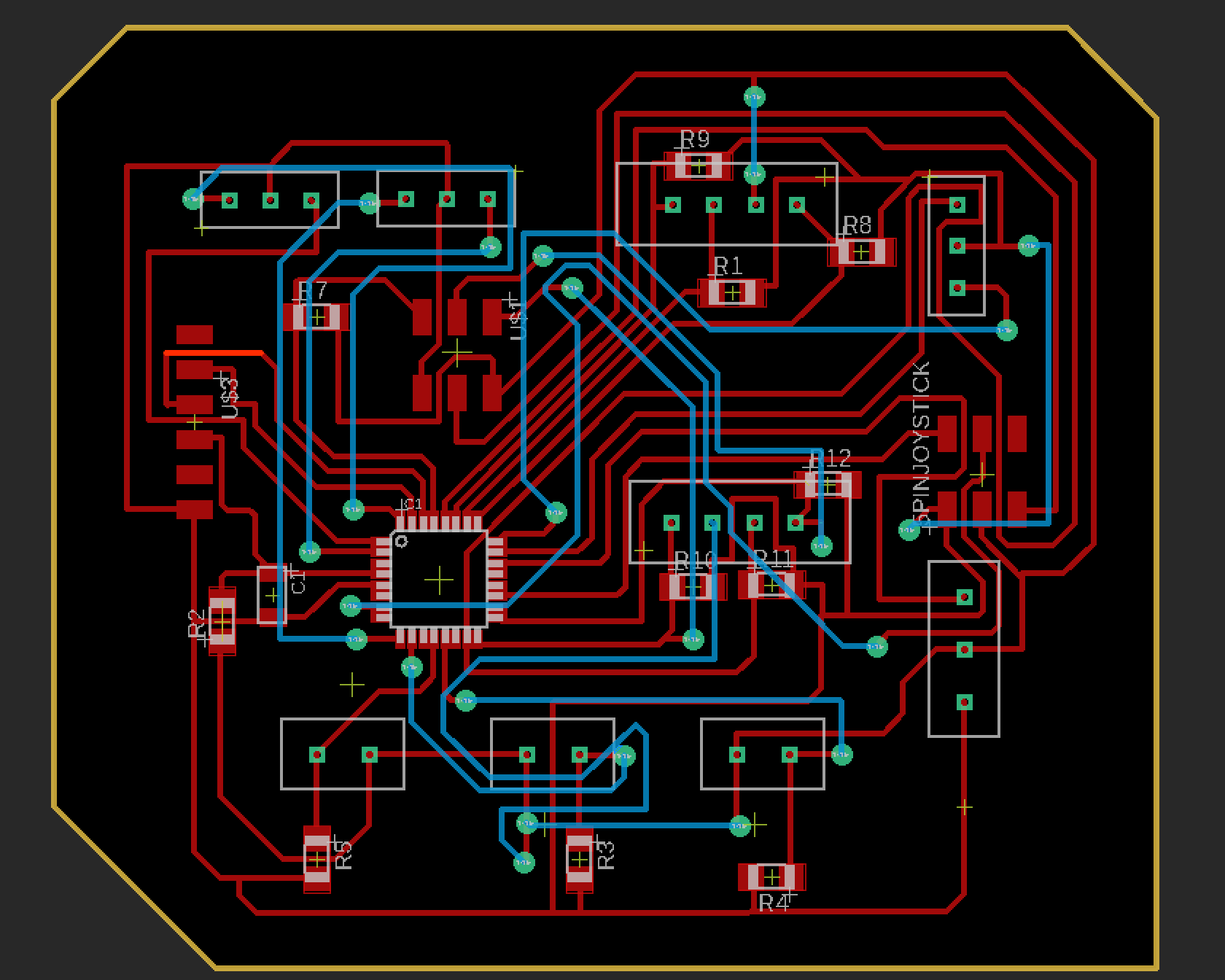
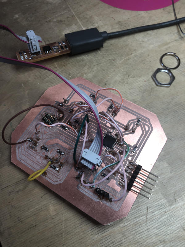 My pcb is not super complicated but it contains a lot of connections between individual elements in total 14 dig+3 Analogs+ TX RX VCC and more.
Due to the fact that not all elements were in the libraries, I've created some of my own and I have to admit that it's very satisfying. Moreover I had to design pinouts for particular devices that were not soldered to pcb.
In the project I proposed a double-sided option but due to lack of suitable tools I made one side with wires connecting the pins. Unfortunately, in combination with the whole mass of cables from the devices, it gave a small mess, but it was possible to make it impossible in the case).
My pcb is not super complicated but it contains a lot of connections between individual elements in total 14 dig+3 Analogs+ TX RX VCC and more.
Due to the fact that not all elements were in the libraries, I've created some of my own and I have to admit that it's very satisfying. Moreover I had to design pinouts for particular devices that were not soldered to pcb.
In the project I proposed a double-sided option but due to lack of suitable tools I made one side with wires connecting the pins. Unfortunately, in combination with the whole mass of cables from the devices, it gave a small mess, but it was possible to make it impossible in the case).
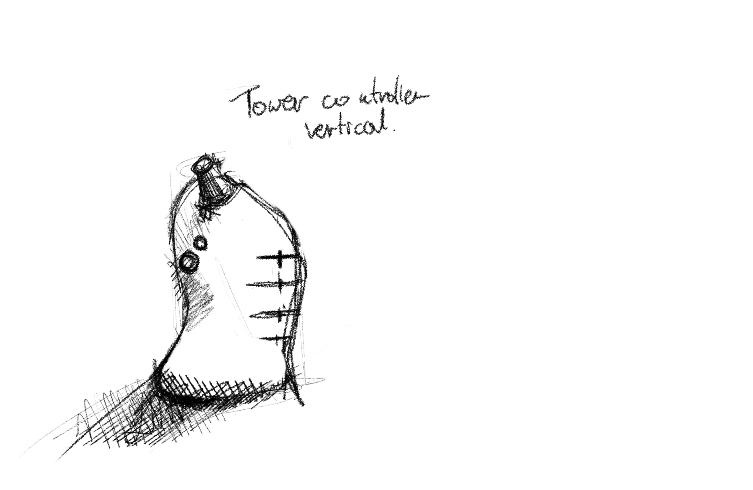
Form
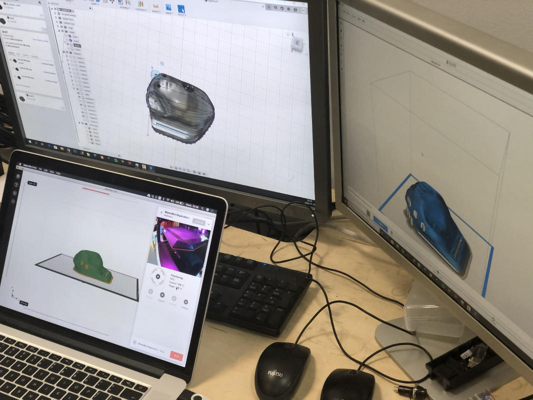 I think that's probably the part that I was most concerned about. As you can see in the pictures and films, I made a model out of clay first and then I scanned it in 3D and then I did a retopology of the obiketu and added some space for the buttons and cylinders and so on. I did this for a very important reason, because the device is very expensive in terms of its ergonomics and functionality. and there is probably no more important issue with a device that takes all day long than comfort.
I used the Meshroom from alice vsion to scan in 3d! a super program, for retopology i used fusion 360.
I think that's probably the part that I was most concerned about. As you can see in the pictures and films, I made a model out of clay first and then I scanned it in 3D and then I did a retopology of the obiketu and added some space for the buttons and cylinders and so on. I did this for a very important reason, because the device is very expensive in terms of its ergonomics and functionality. and there is probably no more important issue with a device that takes all day long than comfort.
I used the Meshroom from alice vsion to scan in 3d! a super program, for retopology i used fusion 360.
Did I manage to achieve my goal
In most cases yes, but I would certainly like to replace the ftdi with the usual usb and change the buttons, it can be tempted to work with javascript which could create more versatile possibilities to work in practically any system.
Licence
Because I want the product to be under an open license, everyone will be able to create their own version of the device, but this does not mean that he will not be able to be financed in any other way than selling the finished product donation option when downloading files (similar to what it is on arduino site) sale of finished electronic kits for DIY sale of full sets to be assembled together with a printed case support and grants from companies distributing programs using manipulators