Week 05:3D Printing and 3D Scanning
Up in this week all about 3D printing and 3D scanning.Assignments
Group assignment:- test the design rules for your 3D printer(s)
Individual assignment:
- design and 3D print an object (small, few cm3, limited by printer time) that could not be made subtractively
- 3D scan an object (and optionally print it)
Google drive with all files
3D Printing History
SLA and the beginning
The history of 3D printing started in 1981 in Japan with Dr.Hideo Kodama patent application. It is a oldest known record of device that used laser beam to cure resin. Unfortunately his patent did not went through.Next idea of rapid prototyping have been developed in France by Jean-Claude André, Olivier de Witte, and Alain le Méhauté. This trio also filed the patent in 1984 but lack of funds made them to abandon the project.
At the same time, in 1983, Charles ("Chuck") Hull was more lucky than his predecessors. He started working on a machine that could cure resin by use of UV light, layer by layer to create final part. He was given founds and small lab to work on his project. In the same year Chuck sucesfully printed is 1st part. In 1984, three weeks after trio from France, Hull filed his patent. As the patent from France did not went through, Chucks patent did. Patent was issued in 1986 and the method from now on was officially called Stereolithography, right after that Chuck started his company and after 2 year released 1st commercial product, the SLA-1.
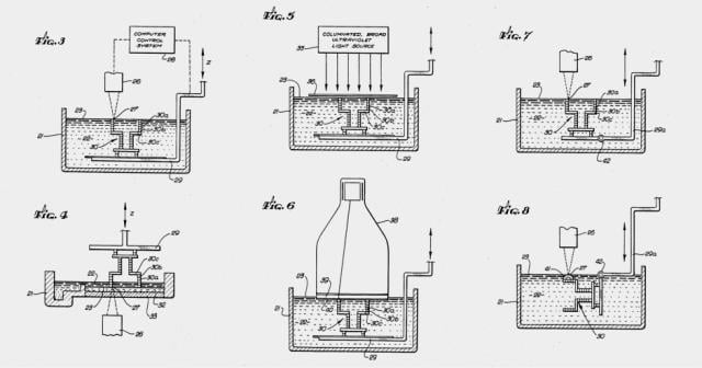
Figure from filed patent explaining the operation bacisc of the method[1].
Events of Charles Hull are marked as a beginning of 3D printing industry.
SLS
Also in 1988 there was another brakethrough in the world of 3D printing industry. The SLS (Selective Laser Sintering) method was in developement and Carl Deckard had filed his patent for it.
[2]
The first SLS 3D printer, called by Carl, Betsy, was able to produce only a simple chunks of plastic. But as Carl said at this time the main purpose was to test the idea not the quality.
FDM
Developement of next method was led by Scott Crump. He submitted the patent for this technology also making the "FDM" a trade mark of his company "Stratasys". Right now Fused Deposition Modeling is one of the most known additive technologies, also called Fused Filament Fabrication. The patent for FDM was finally issued in 1992. This event started intense developement of this technology on many fields, for ex. medicine.The core technologies overview
Main term in 3D printing is "layer" a large part of additive technolgies are based on layers. It is a main factor that describes the each technology and defines the quality or possible application.FDM/FFF
Fused Deposition Modeling or Fused Filament Fabrication, one of the most well known additive technology. This technology is based on heating ,till plastification, solidified polymer material called filament. Then machine put the plastified material on the heated bed in a form of paths. The paths together creates a layer, layer by layer creates in the end whole 3D printed part.
SLA
Stereolithography apparatus, method favored by jewellers, dentists and board games hobbysts. Method that gives high quality prints. Bases on solidifing liquid resin in with use of UV light. The UV light can come from laser or projector, depending on the machine used.
SLS
Selective laser sintering, method that bases on sintering powdered material, in most cases nylon or polyamid, with use of laser.
Grup Assignment
Our group assigment in this week was to test the design rules for 3D printing.
One of the inspiration that we had were design rules supplied by 3D Hubs company.
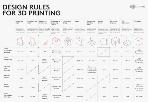
As said before we used the rules from 3D Hubs as insporation and recommended for new users, during work with the printers we have developed some of ours rules for design for our machines.
These are individual things that is different to each printer and user. Something that comes with experience gained in time.
Furthermore we have supplied some additional rules for 3D printing settings that can help new users to imagine how the print will look like basing on the setting set in slicing software.
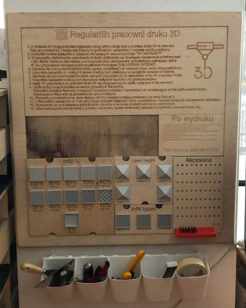
This is a main board that contains use rules of the 3D printing workshop, how to proceed before/during/after using the machine and settings samples for slicing software.
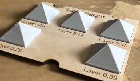
This board show how each layer setting looks like.
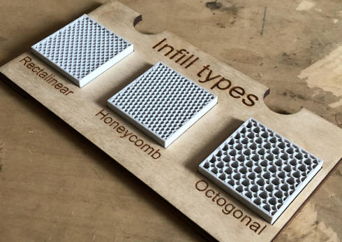
This board show how each infill type looks like.
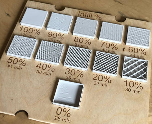
This board show how each procantages of infill looks like and what is the difference between them in printing time.
Test prints
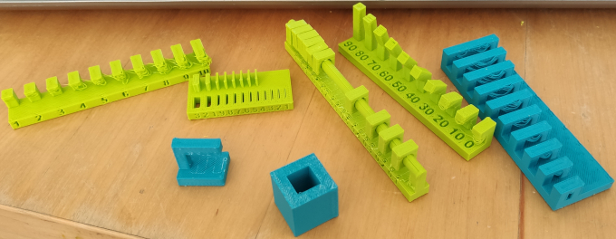
We decided to test our printers with test prints supplied by Neil of FabAcademy. Here are some results.
All test were run on Zortax M200 printer on ABS with standard parameters and layer 0.19 mm.
Unsupported Overhang
Unfortunately overhangs does not come out too well without supports, as visible on the photo above. Maximal unsupported overhang distance is 1mm wihout high loss of print quality.
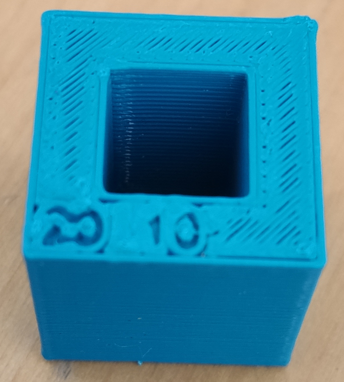
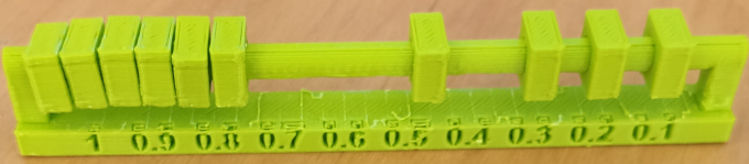
Wall Thickness
As we can see inner thickness can reach even 0.1 mm but wall thickness outside is limited only for 0.5 mm and higer.
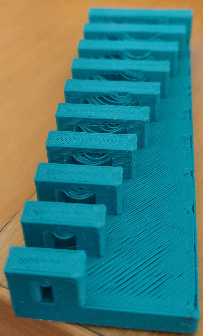
Unsupported Angle
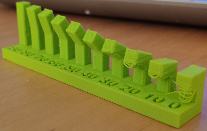
Photo shows that lowest unsupported angle is 30 degrees. It is worth mentioning that we could reach better results by lowering the layer height. It would shorten the distance between each "step" giving each layer better support, thus better quality without supports.
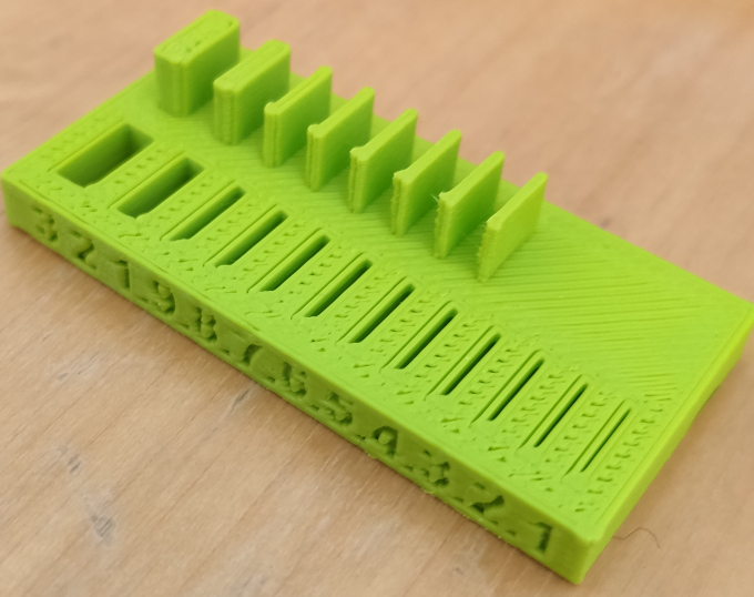
Dimensions
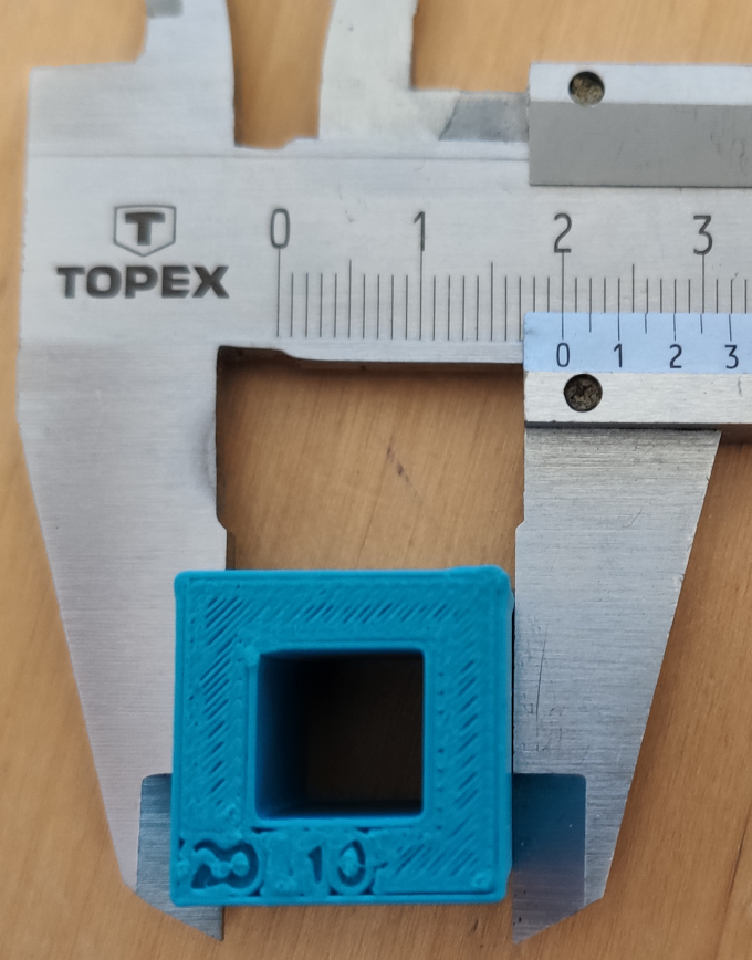
This test can show us a dimensional stability of the printer. From the photos we can see that each dimension is preserved.
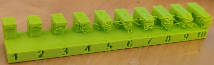
Unsupported Bridging
We can clearly see that Zortrax is not good in dealing with bridging method :P
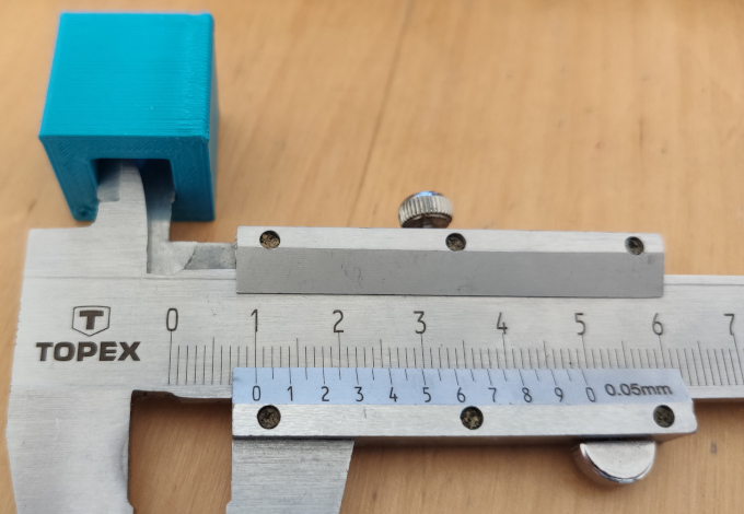
Clearance
Test print that shows us what is the minimal distance between parts and they still can move freely.
From the test visible on photo we can tell that 0.4 is the shortest gap between two bodies that we can achive.
Surface Finish
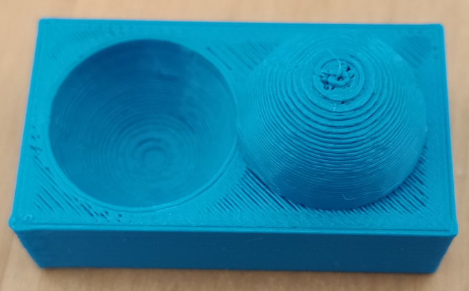
Print on which we can see how the surface is finished by printer on such specific surface as inner and outer dome. It is also good to metion that each layer height would give us different result.
Individual Assigment: 3D Printing
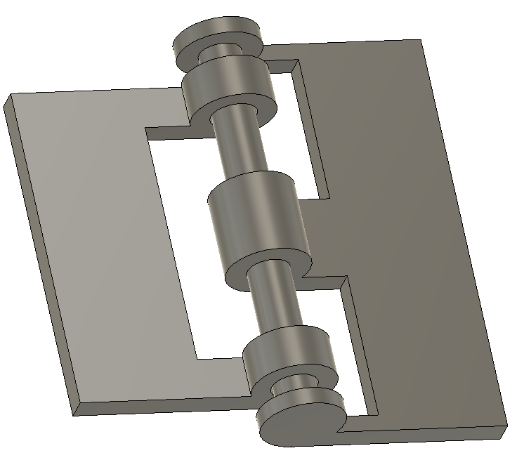
One of our individual assigments for this week was to design something that is impossible to be made with use of subtractive methods.For this I choose a hinge. Fastly modeled in Fusion 360.
The reason I choose hinge for that assigment is that the hinge is made out of two parts that move freely, revolve around one center of rotation. There is a small gap between one of the parts and the shaft in the center. Such model and design whould be hard to make with subtractive method thus of the accessability to the narrow spaces.
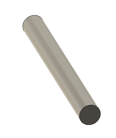
I started with bar that will be a center part of the design.
Then I added few rings. Three for one half of the part and two for second part. Also a additional plane that will be used for construction of the rest of the model.
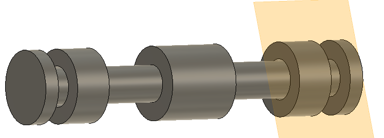
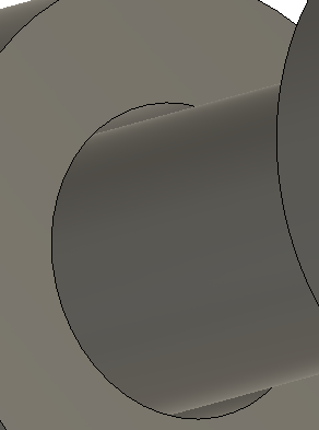
I made 0.4 mm clerance between the bar and two rings to make the hinge move freely.
Then half of 1st part came in.
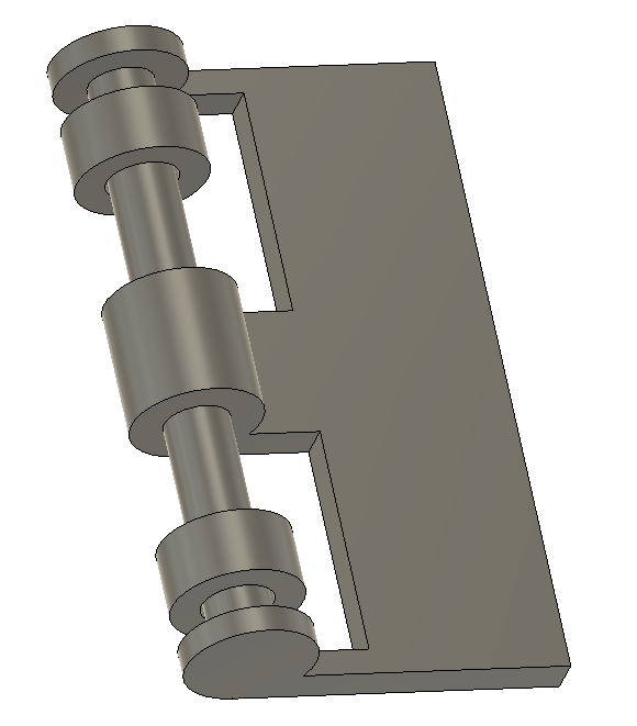
And second half.
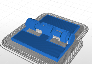
Into Z-Suite!
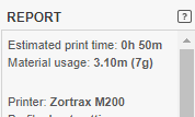
Time is good so lets print!
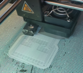
3D printed real part.
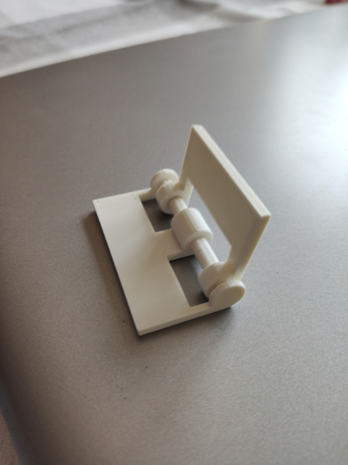
Printed model moved freely as shown on video:
Individual Assigment: 3D Scanning
Second individual assigment for this week was to 3D scan any object. For this I decided to use a hand 3D scanner available in our Lab. It is an Sense 3D.
I decided to scan a handle, for my mother kitchen tool, which got broken and I was asked by my mother more than a year ago to reprint it.

Before I can scan it I need to fix to somehow so it can be exhibited and accessable from every angle for proper scaning.
This is the moment when creativity comes handy :)
Unfortunately the outcome from this scanner was very bad. I have tried looking for some tips on the internet. I have covered the part with ducktape to make it more visible for the scanner but unfortunately it did not worked too well as well.
Here is a video showing how was the examplary output.
After failing few times I decided to drop this method and device and use a photogrametry method.
I learned how to use this method from this article: https://blog.prusaprinters.org/pl/photogrammetry2-3dscanningsimplerbetterthanever_32353/
This article bases on using a Meshroom software with AliceVision workflow.
The base of photogrametry are photos. I have to make many many photos of the piece I wish to "scan" and from as many different angles as possible.
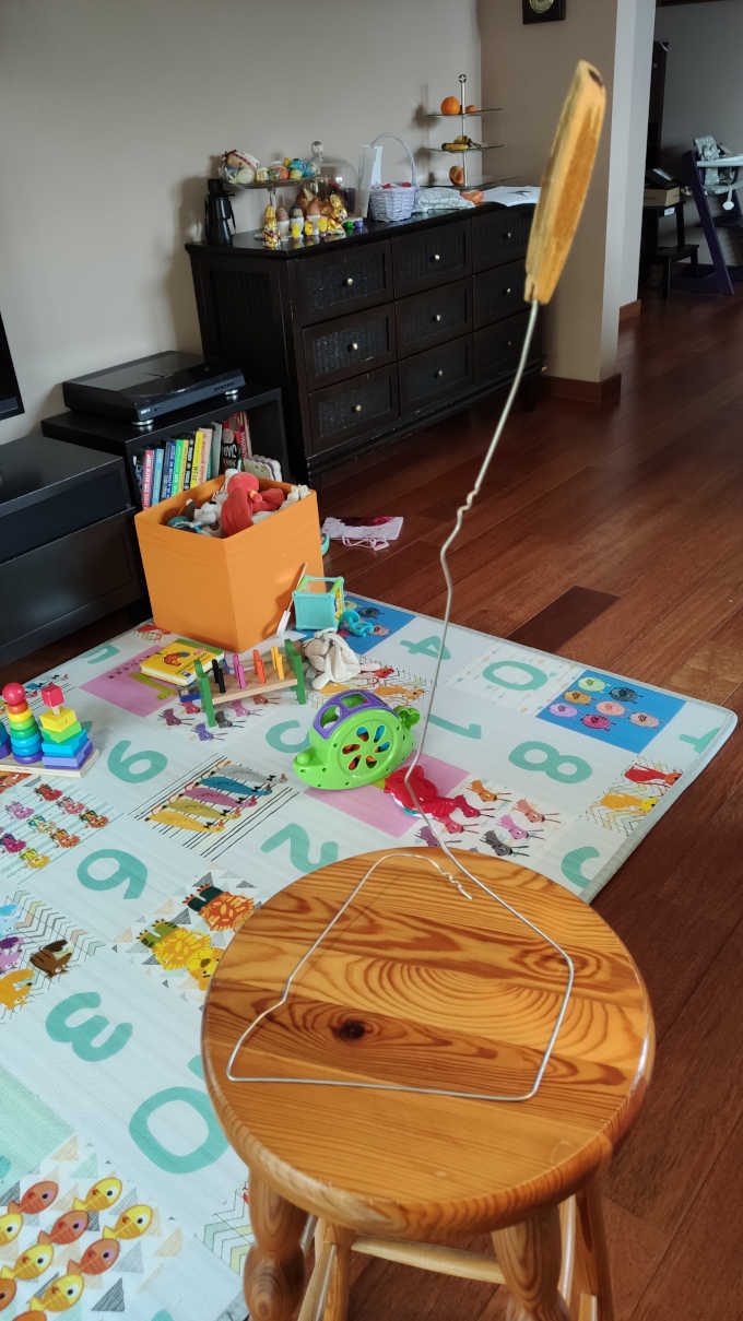
To make it easier I had to think of some "device" that would allow me to do that. So again working far from FabLab makes me use all of my in-home creativity skills. So this is what comes out of it:
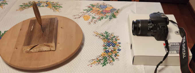
The piece in placed on wood screw that is screw into a piece of wood which is placed on a rotating wooden plate , that is normally used for cakes. Wooden plate is rotated by me by hand and the camera is set for contantly shooting mode.
I took my Cannon 700D camera for this job. I made around 250 photos. Now I need to load everthing into the software.
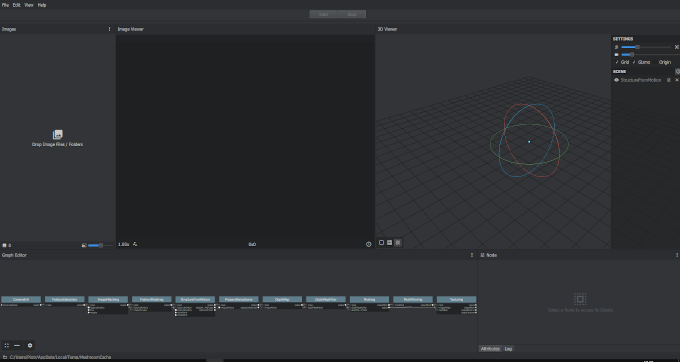
After loading the photos all is to do is to press green "Start" button at the top and the computing process will start.
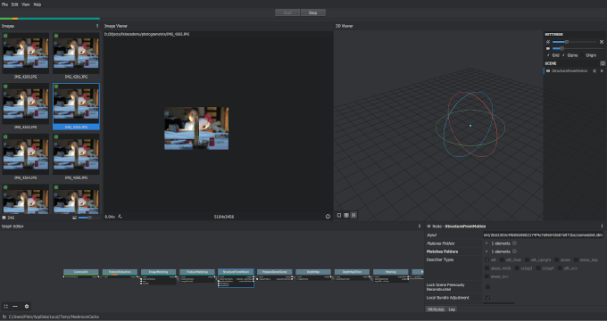
After hour of computing 246 photos I finally had some output in form of cloud of points and overlapsed photos.

The white points with rectangles are POV of one photo and predicted position of the camera. In the middle we can see the cloud of points that form a promitive visualisation of the model.

Close-up on the cloud of points.
After this there is a long computing process for dense mesh and textures so I left the software running over night.
In the morning I recieved the output as following:
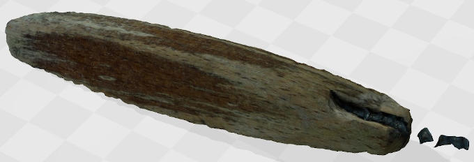
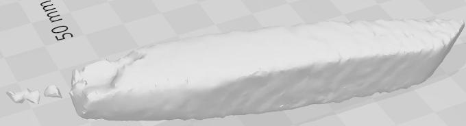
The results are not super high quality but I am still happy with them.
Bibliography
[1]Img. from https://www.3dsystems.com/our-story[2]Img. from https://all3dp.com/2/history-of-3d-printing-when-was-3d-printing-invented/