Group Assigment
There is no standardized way of producing PCBs in our fablab. Some users sub-contract more complex layouts and some of them are pickled in a friendly hackerspace or have their own PCB milling machine. In order to produce the first PCBs we came up with machines on which we could do it... and it turned out that we had quite a few:
Starting with ZMorph, multitool laser, milling machine and printer in one. Unfortunately, it was problematic to force the machine to milling from MODS unfortunately there were too many differences in gcode.

Our next choice was our large CNC milling machine which thanks to servomotors has a very high accuracy, but we left it at the very end as an option of last hope.
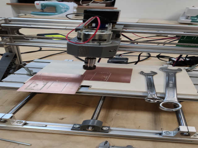
Lastly diy milling machine based on WOODPECKER GRBL 0.9 controller, where gcode from mods works surprisingly well ,unfortunately, it turned out that the Z-axis is rotated, but we have managed to deal with this problem by changing values in the code.
Surface leveling
After selecting the milling machine, we needed grblControl software installed on a computer with windows system, a very simple software for basic operation of the machine. The first thing after installing the software and understanding the basics of operation was to level the surface which in our case was made of plywood with a 3.175 mm diamond cutter.Fab Modules
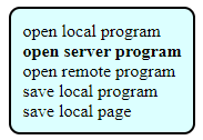
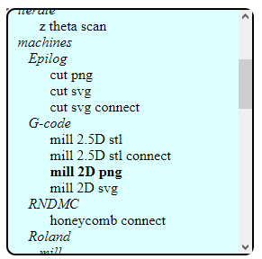
Digging into fab modules was quite a ride for the first time. We did not understand a thing at the beginning. It took us few minutes to get into it but after all we managed to generate NC code for our cutter. We started with opening the server program by first clicking right mouse button and then choosing "programs=>open server program" and in the list of all possible pograms we found Gcodes and "mill 2D png". We chose PNG because we are following the tutorial supplied in Fab academy content: Fab Isp tutorial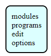
And wooohooo... A lot of new windows with many options... So we started checking every windows what it does and what it gives and takes. It took us a while to figure everything out but we made it.
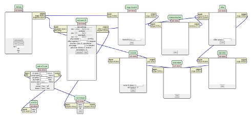
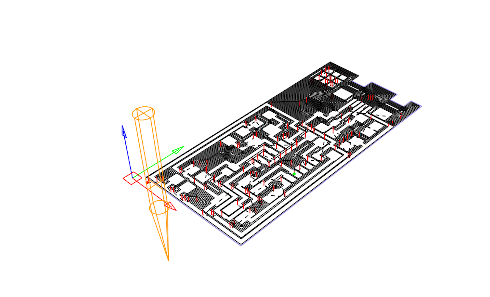
Next thing that we had to do, after figuring out how the 2d milling mod works, was to define how big milling bit we need. We managed to calculate few paths for cutting. After few tries we decided that the best will be 0.4 mm milling bit, as it fits in all necessary narrow paths and it does the job quite fast. So now times come for milling!!
PCB Milling
As we created our millig gcodes, now we need to set everything up on the milling machine.- we leveled the ply wood - we attached the pcb laminate to the ply wood
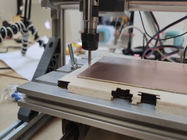
Now we set the gcode on the software for the milling machine.
It wasn't perfect after first time...
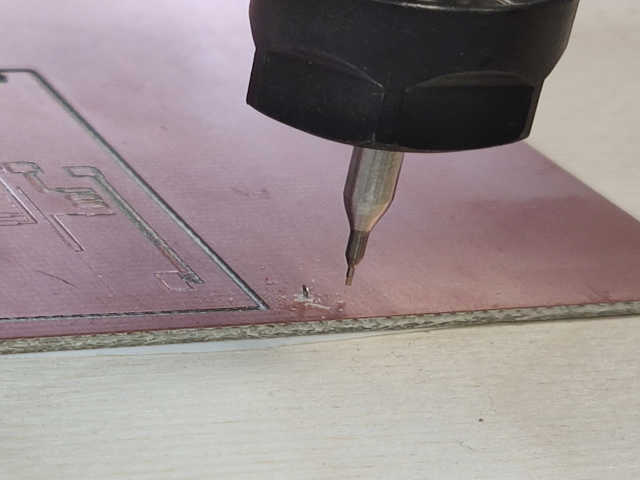
But after few tries.
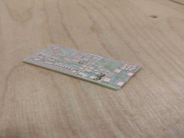
We finally managed to get nice board :)
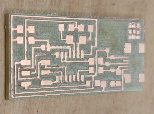
Time to stuff it with some components!
Soldering
So lets start with adding components to the milled board. As I can read from the FabAcademy tutorial I need to solder to board following components:- 1 ATTiny 44 microcontroller
- 1 Capacitor 1uF
- 2 Capacitor 10 pF
- 2 Resistor 100 ohm
- 1 Resistor 499 ohm
- 1 Resistor 1K ohm
- 1 Resistor 10K
- one 6 pin header
- 1 USB connector
- 2 jumpers - 0 ohm resistors
- 1 Crystal 20MHz
- two Zener Diode 3.3 V
- one usb mini cable
- one ribbon cable
- two 6 pin connectors
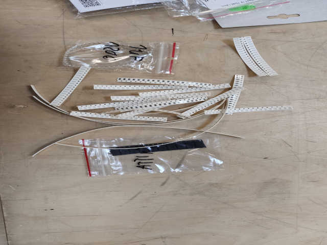
I already know something about soldering. I had to practice a bit before I recalled all the skills thus not everything is perfect but I managed to solder some stuff.
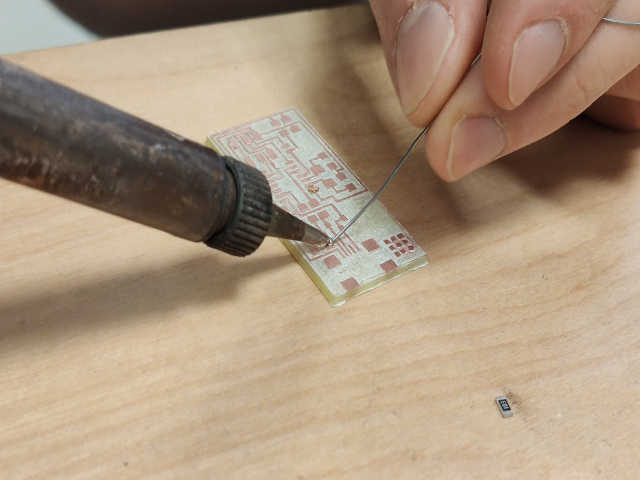
I started with adding some solder onto the board in the place where component should be.
After that I putted the component in the proper place and heated the area with hot air gun so the soler melts and connects with the applied components.
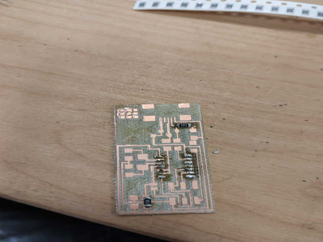
I continued the following procedure with rest of the components.
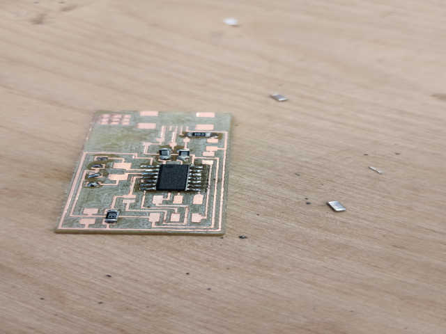
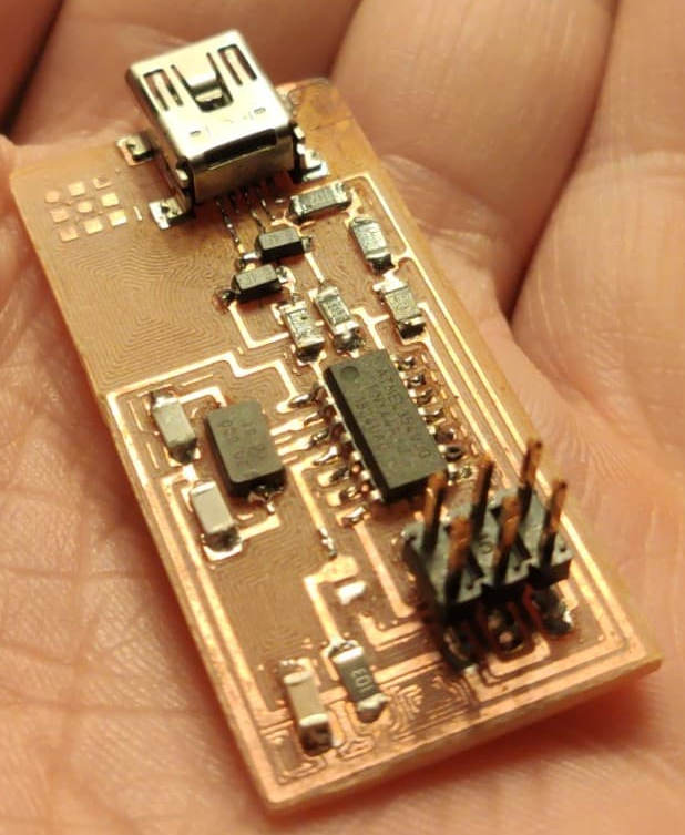
At the end the board looks as following:
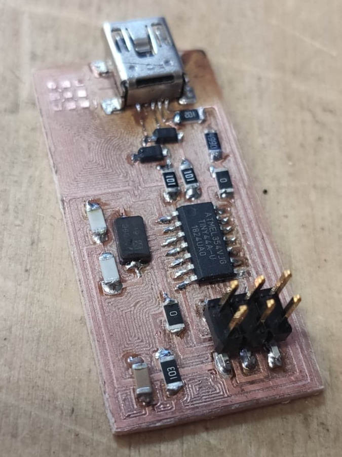
Now on to programing!
Programing
After I milled and soldered the board I can finally connect it into my laptop.Before I do it I read the instruction provided by FabAcademy on:
FabAcademy Tutorials: FabISP Production and Programming
1st thing to do is to simply connect the board to the PC via USB cable, I was told that better is to do it by connecting the ISP into the USB Hub first and then into my laptop and then see if it smokes...
After connecting the board for the 1st time nothing happened and everthing seams to be OK!
Now lets proceed with the instruction.
First of all I need to donwload necessary stuff, which is:
1. AVRdude
2. FabISP Firmware
3. Usbtinyisp drivers
Now I connect our FabLab FabISP programmer, premaded and I install all necessary drivers to make it work properly with my laptop.
I disconnect the FabISP from our lab from my laptop and connect into it my self made into the 6-pin programming header. It is necessary to make sure that I am connecting all cables properly. It is easy to connect it wrong and set the VCC into wrong line thus burning the board.
After recoonecting the FabLab's FabISP, with my FabISP connected into it, everything seams to be fine.
Now I need to edit the make file from FabISP firmare, in the standard version it uses ATAVRISP2 Programmer but I am not thus I need to make small change in lines so it will use USBtiny.
From:

To:

Now I open the command prompter on Windows and enter the firmare directory
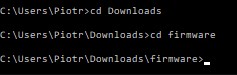
Next thing is to compile the firmware. To make it I type
make clean in command prompter.After reciving the possitive response from the system I type
make hex and make fuse right after that and did not responded sucesfully...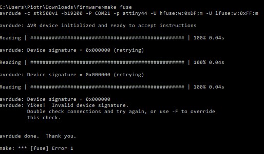
It turned out that not all ATtiny 44 pins were soldered properly. After resoldering the command worked properly.
If all above commands finished sucesfully I can finally program my boards with
make program and the final procedure looks as following: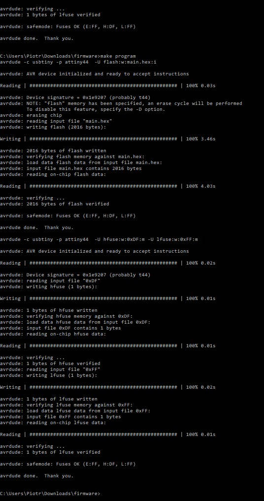
Now I can check if my board is working properly by connecting it into my laptop via USB cable.
If everything is OK I will see the board show up in device manager.
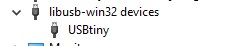
And it works!
All is left is to desolder the 0 Ohm ressitor to make the board work as a programmer.
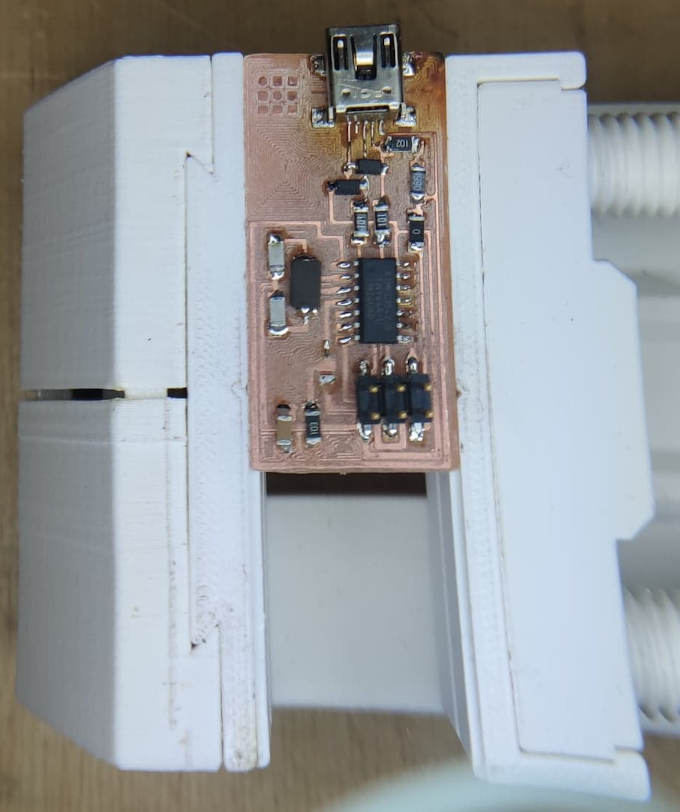
Working board: