Input Devices
Group assignment
Probe an input device(s)'s analog and digital signals.
Document your work (in a group or individually).
Individual assignment:
Measure something: add a sensor to a microcontroller board that you have designed and read it.
Learning outcomes:
Demonstrate workflows used in sensing something with input device(s) and MCU board.
This week I should add a sensor to a microcontroller board that I had to design it in Electronics Design week and read it. Then I should demonstrate workflows used in sensing something with an input device(s) and MCU board. But until now our lab is closed, Instead of that I will use the Arduino. I had worked with Arduino before and some other microcontrollers like Micro Bit and KittenBot on a basic level. As we know now from the previous week Embedded Programming the Micro-controller is a microcomputer used for control purposes, and for data analysis. It has an internal CPU, RAM, IOs interface. A microcontroller is a subset of Arduino. Every Arduino is a microcontroller but not every microcontroller is Arduino. To know more about the difference between Microcontroller and Arduino.
Microcontroller VS Arduino

what does Input device mean?
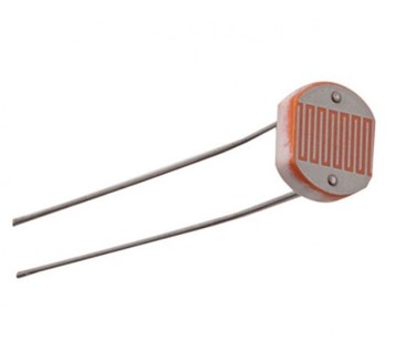
Input device is a piece of computer hardware equipment used to provide data and control signals to an information processing system. I found another kit I ordered last year, It includes more than 10 sensors, but all of the are sensor modules. It is no difference between the sensor and the sensor module. Sensors use to sense stuff. for example, Pushbuttons, touchpads, tilt switches, photo resistors, thermistors, Gas sensors, tilt sensors, motion sensor, heart sensor, touch sensor, moisture sensor, laser sensor, and more!
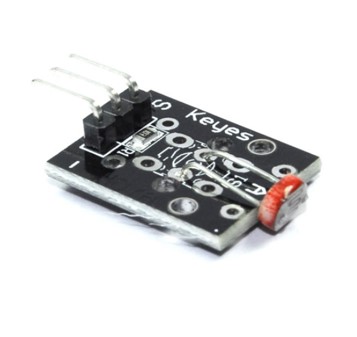
Sensors modules use also to sense but in an easy way!
The only difference between the sensor and module is that the module will have a filtering capacitor and pull-up resistor inbuilt, and for the sensor, you have to use them externally if required. Modules are designed to be easy to put together into a larger system.
Individual assignment:
I used in this assignment the Arduino and the touch sensor, one of the sensors I am thinking to use it in my final project. the coding was by Arduino IDE programming environment. I had explained the IDE environments in previous week Embedded Programming . the new is the touch sensor as an input, step by step I will explain more about it.
Touch Sensor
A touch sensor is an electronic sensor used in detecting and recording physical touch. Also known as tactile sensors, it's a small, simple, low-cost sensor.
Touch Sensor Pin Wiring:
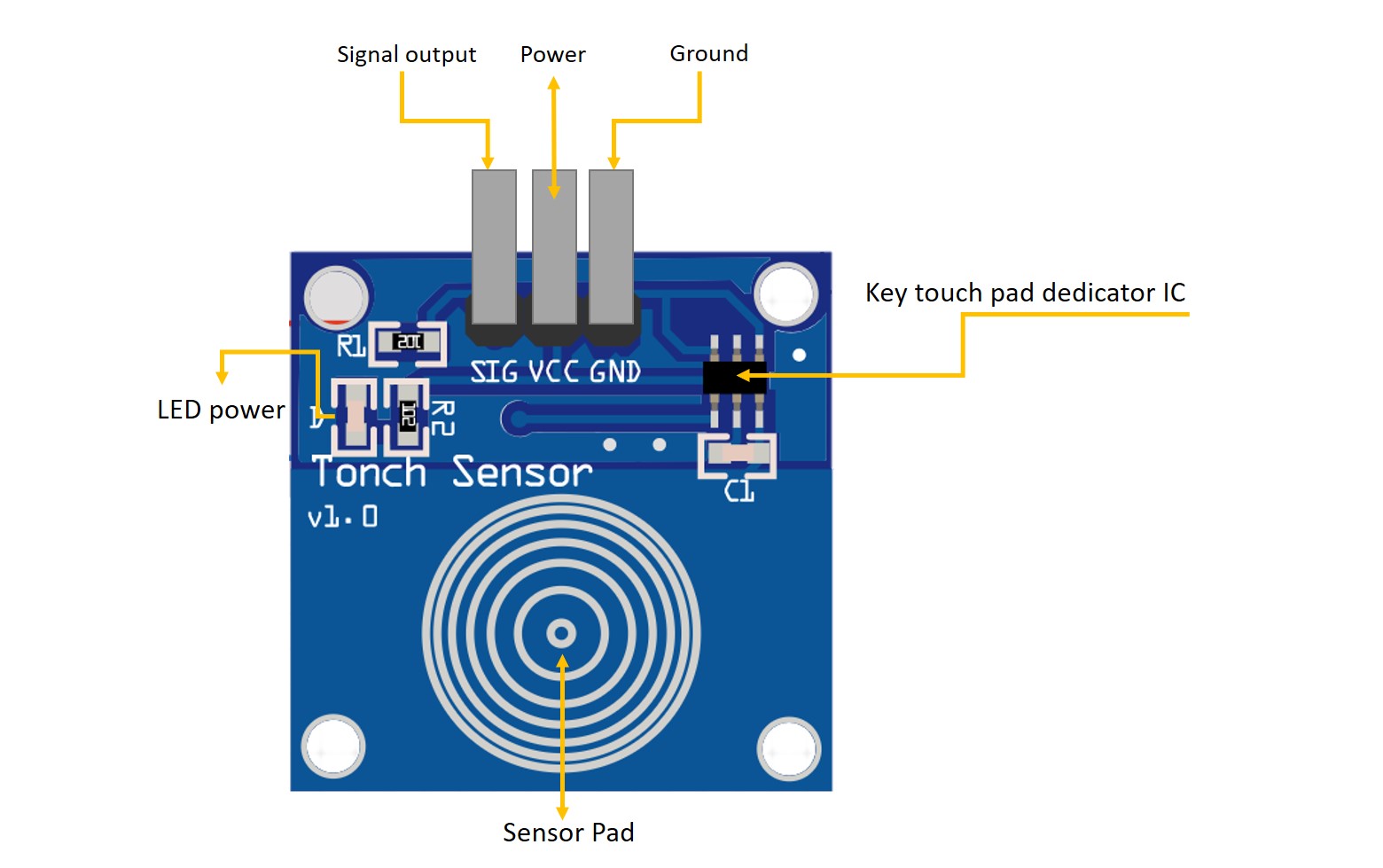
- GND pin needs to be connected to GND (0V)
- VCC pin needs to be connected to VCC (5V or 3.3v)
- SIGNAL pin is an output pin: LOW when it is NOT touched, HIGH when it is touched. This pin needs to be connected to Arduino's input pin.
- Power Indicator : Green LED, power on the right that is shiny.
- Touch area : Similar to a fingerprint icon inside the area, you can touch the trigger finger.
- Key Touch pad detector IC, it is suitable to detect capacitive element variations.
Testing the Touch Sensor In this project I will let you know the basic operation of a capacitive touch sensor switch module and how it can be implemented with an Arduino board. The touch sensor is connected to the Arduino UNO board as input to act as a security system if anyone touched the LED -the output- will be switched on as an alarm.
Components needed:
- Arduino UNO.
- USB cable.
- Jumper weirs.
- LED.
- Toch sensor.
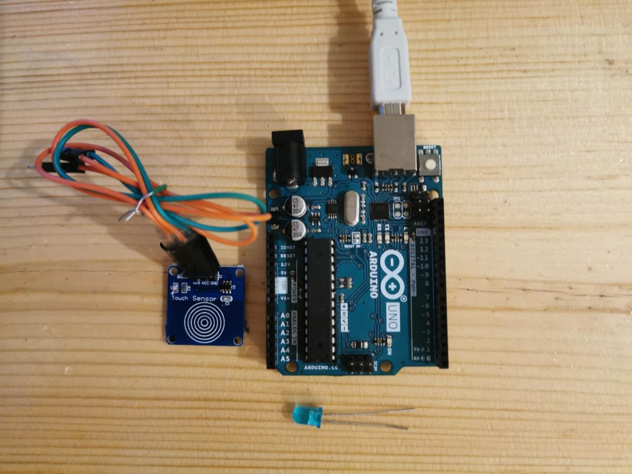
Connctions of the components:
Connction of the Touch sensor:
- GND to GND of the Arduino.
- VCC to 5V of the Arduino.
- SIG-Signal- to digital pin 7.
- Long positive leg to the digital pin 13.
- Short negative leg to GND.
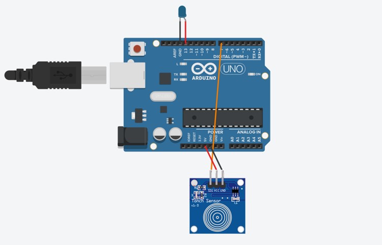
The simulation drowing of the circuit.
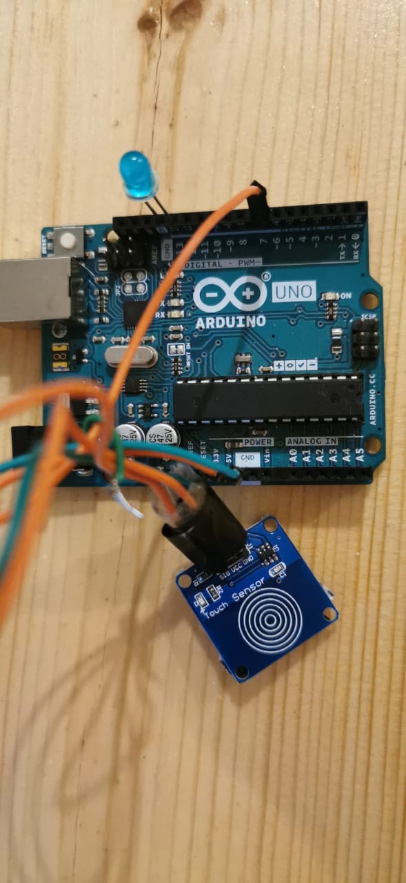
After conncted all the components.
Coding
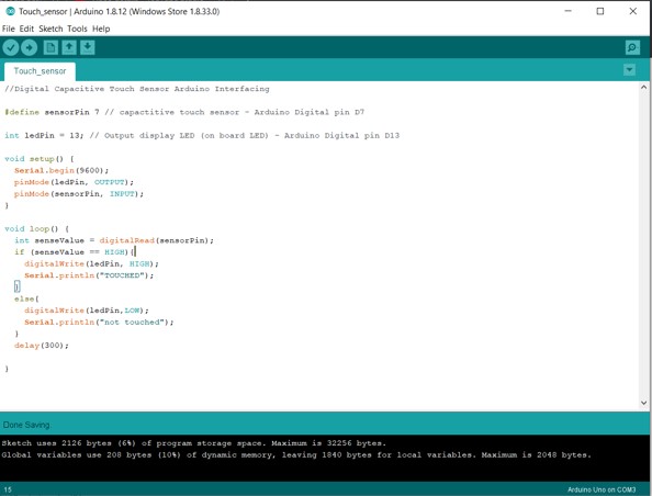
Code
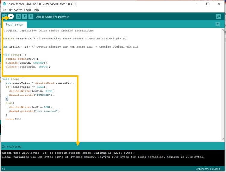
I uploaded the code after verified and checked the errors.
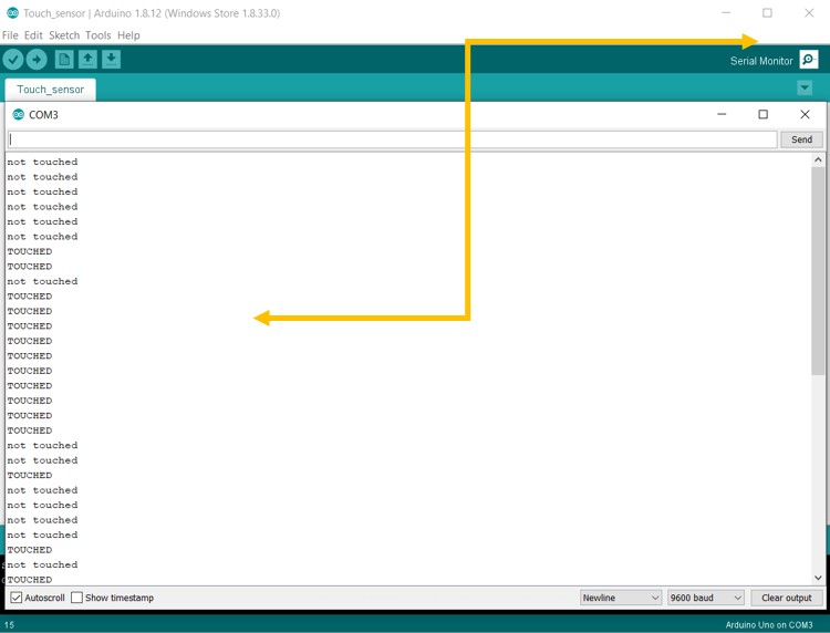
I used the serial monitor this time, to read the digital pin in the Arudino I connected to the signal pin in the touch sensor.
Code File:
Gas MQ-2 Sensor
I decided to test the Gas sensor MQ-2, also with Arduino for experimenting only. Gas MQ-2 sensor is one of the gas sensors kits, they are electronic devices that detect and identify different types of gasses. They are commonly used to detect toxic or explosive gasses and measure gas concentration.
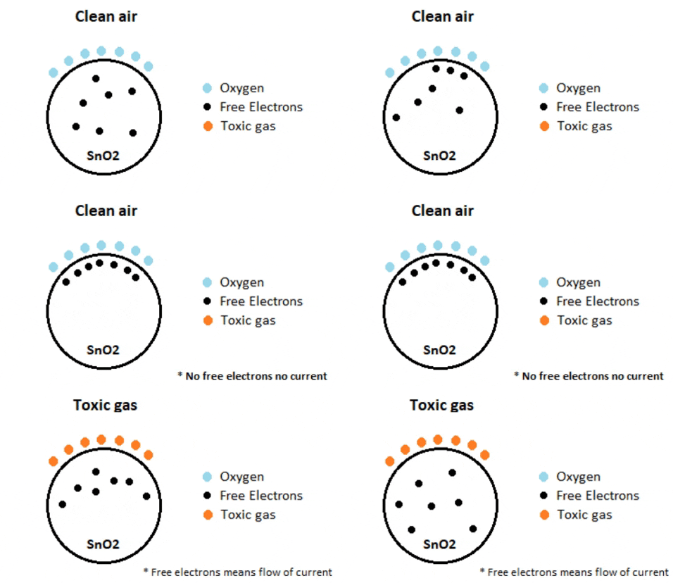
MQ2 sensor senses the flammable gases by the increase in temperature when they are oxidized by the heating element. It is a Metal Oxide Semiconductor (MOS) type Gas Sensor also known as Chemiresistors as the detection is based upon a change of resistance of the sensing material when the Gas comes in contact with the material. Using a simple voltage divider network, concentrations of the gas can be detected.
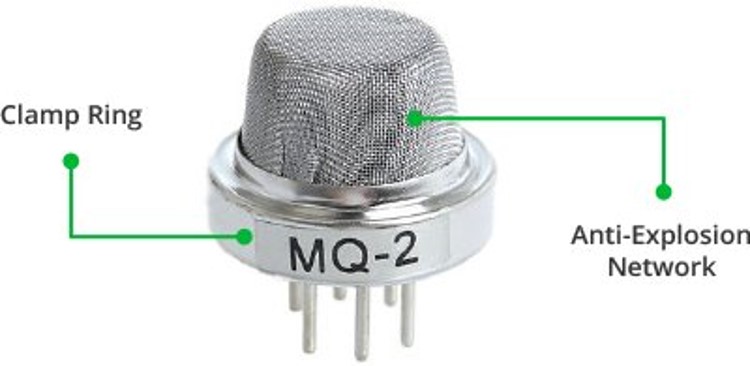
It can detect LPG, Smoke, Alcohol, Propane, Hydrogen, Methane, and Carbon Monoxide concentrations anywhere from 200 to 10000ppm. In the presence of reducing gases, the surface density of adsorbed oxygen decreases as it reacts with the reducing gases. Electrons are then released into the tin dioxide, allowing current to flow freely through the sensor.
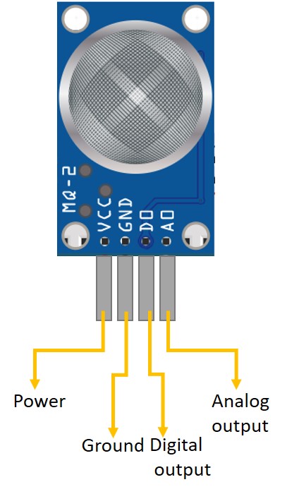
- GND is the Ground Pin and needs to be connected to GND pin on the Arduino.
- VCC is the power pin and needs to be conncted to 5V pin on theArduino.
- D0 provides a digital representation of the presence of combustible gases.
- A0 provides analog output voltage in proportional to the concentration of smoke/gas.
- DAT D0 Indicator LED ,shows that the sensor didact toxic gas.
- PWR Power indicator pin show that the sensor is on.
Testing the Gas MQ-2 Sensor
In this project I will show you how I programmed the sensor to act as a portable alarm system, the code is very simple & basically just keeps reading the analog voltage on A0 pin. It also prints a message on the serial monitor when smoke is detected, and alarm the user by LED lighting and buzzer.
Components needed:
- Arduino UNO.
- USB cable.
- Gas sensor MQ-2.
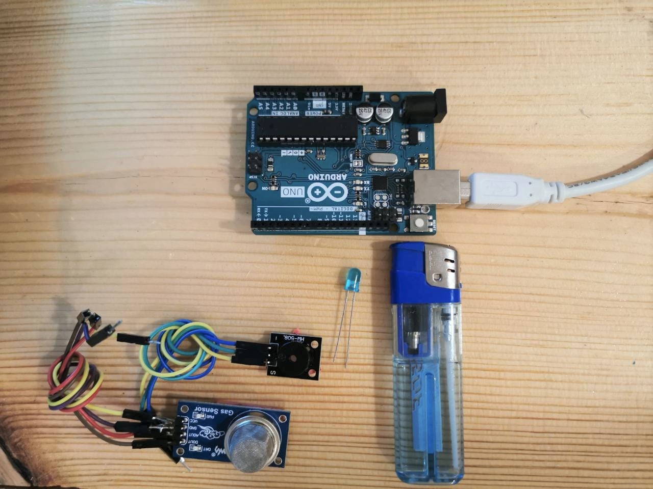
Connction of the components:
Connction of the MQ2 Gas Sensor:
- GND to GND of the Arduino.
- VCC to 5V of the Arduino.
- AOUT to Analog pin A0.
- DOUT to Digital pin 6.
- Long positive leg to the digital pin 13.
- Short negative leg to GND.
Connction of the Buzzer module:
- GND (-) to GND of the Arduino.
- VCC-middle pin- to 3.5V.
- S-sginal pin- to digital pin 8.
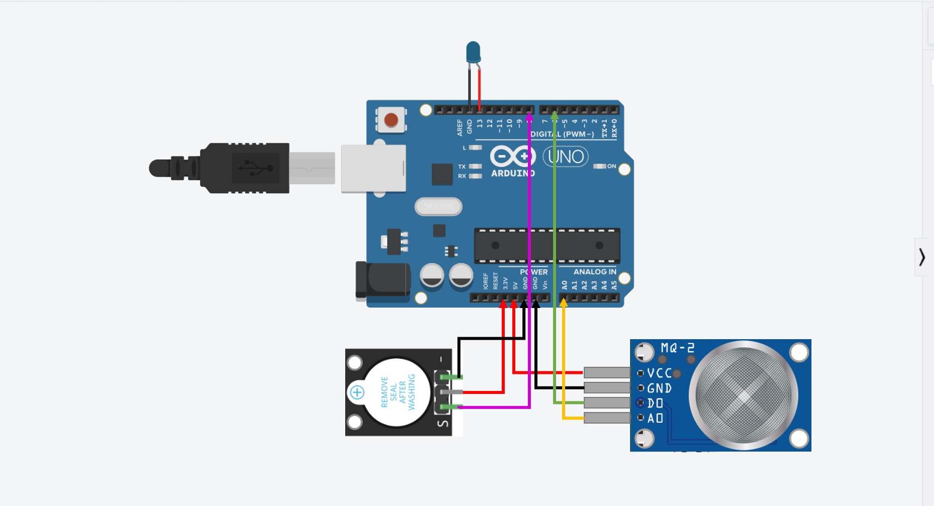
The simulation drowing of the circuit.
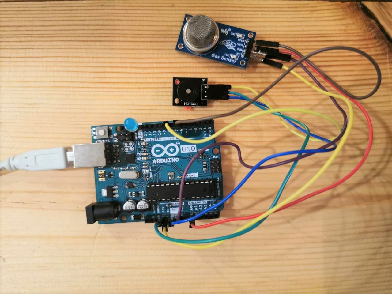
After conncted all the components.
Coding
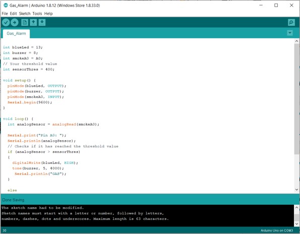
Code
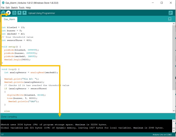
I uploaded the code after verified and checked the errors.
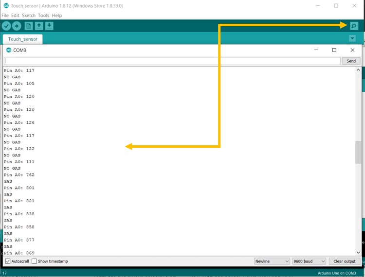
I used the serial monitor, to read the digital pin in the Arudino I connected to the analog pin in the gas sensor.
Code File:
- Gas sensor
- Arduino Uno
- USB Cable
- Water level sensor
Code
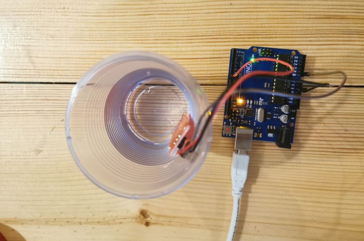
Hydration bottel main circuit
In this project I designed the board by using eagle by adding the below compounentes:- 1x Attiny 44
- 4x Resistor 10K
- 13x Pin holder
- 1x RGB LED
- 1x terminal pin holder
- Water level sensor
Schematic Drawing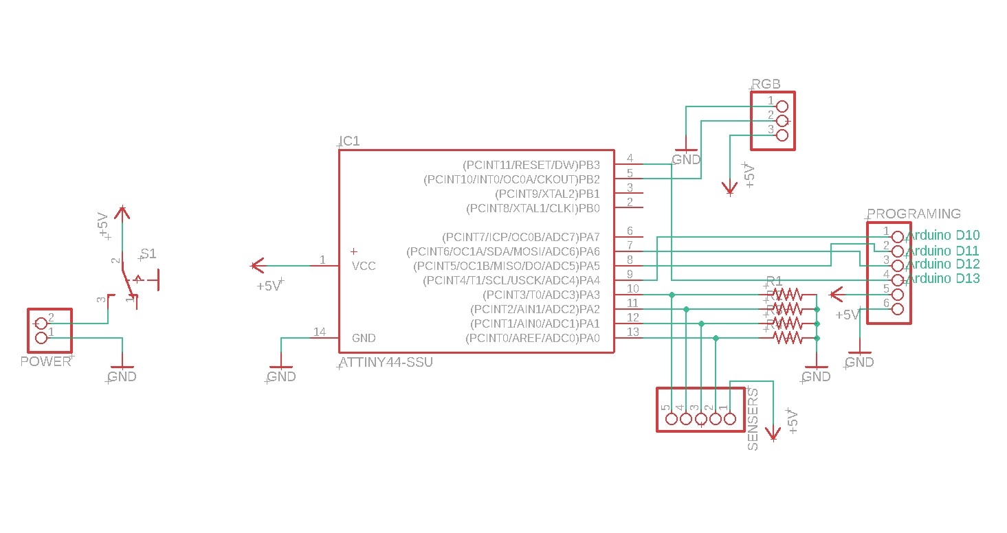
Board Drawing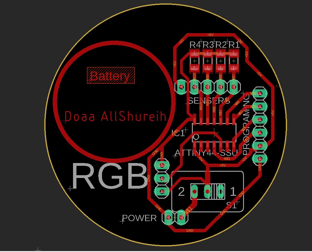
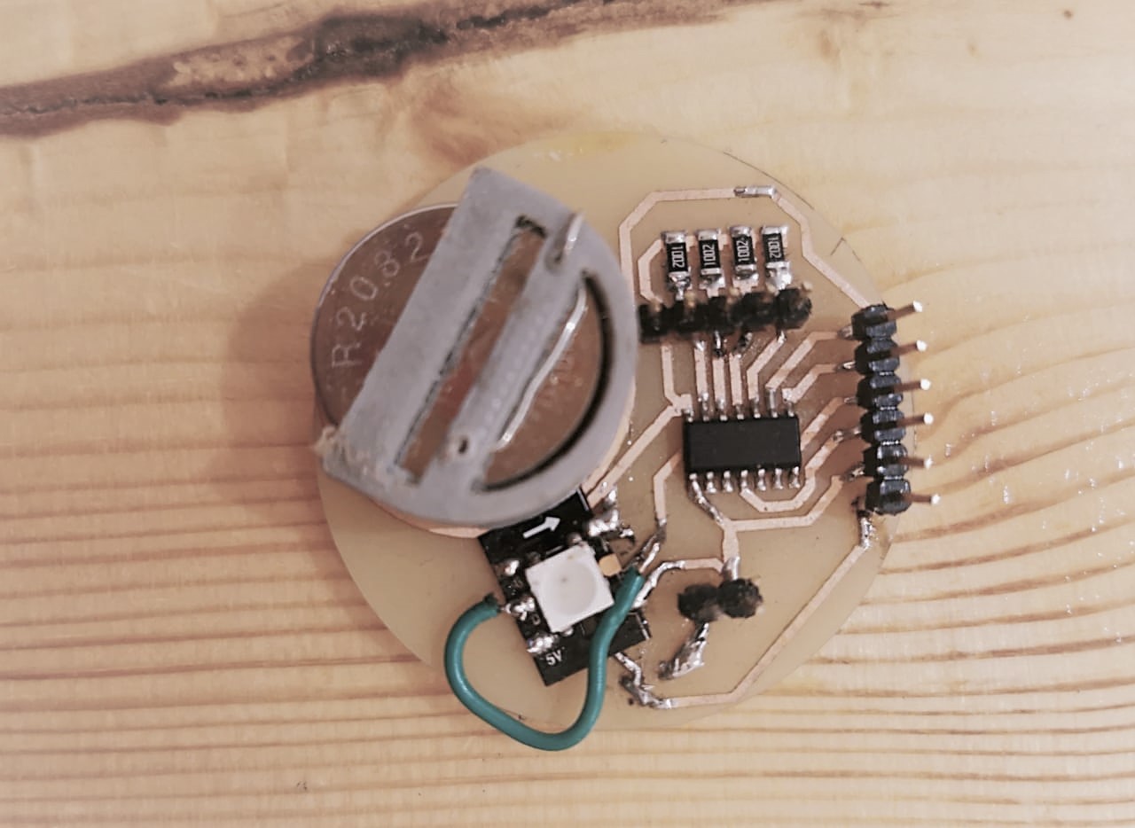
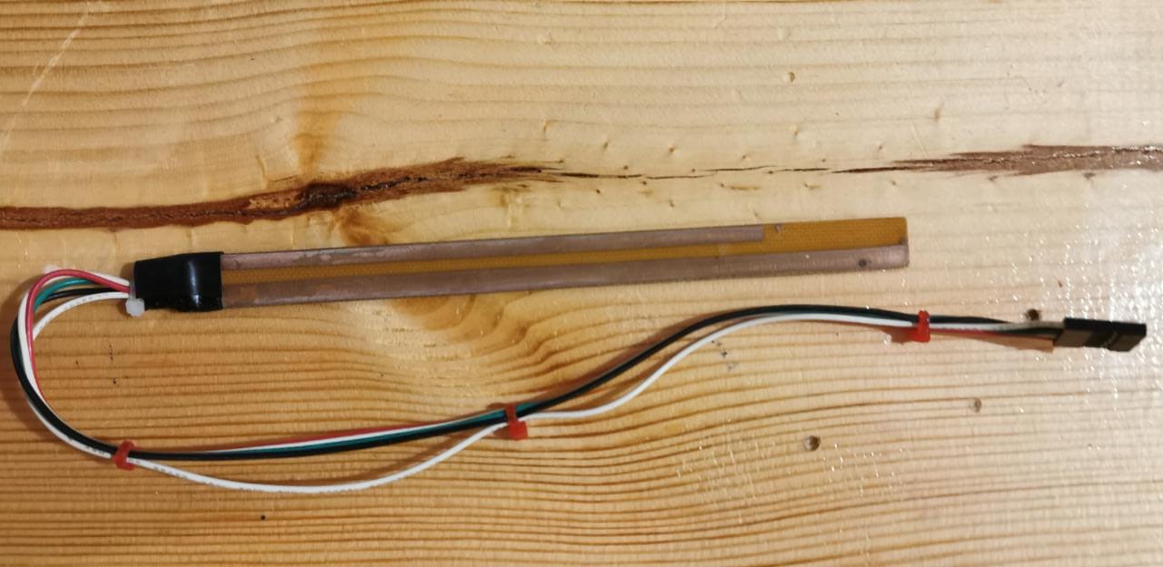
The water sensor.
Code
By using Arduion IDE, I added Adafruit_NeoPixel.h library for controlling single-wire-based LED pixels. each water level has a different analog pin, each level has a different color. I was thinking of using jumper wires with different levels, or copper tape, but I took the advice to make a piece of PCB board with etching different levels, and it works.
Tesing the circuit.
Download files here: - Hydration water bottle SCH
- Hydration water bottle BRD
- The smart hydration water bottle code
Group assignment
Add sensor to my PCB:
The Hydration bottel PCB Circuit
This is the second product of my final project. In this prototype, I design a refillable smart hydration water bottleit should be free BPA, a long-lasting battery. The water bottle will interact with the kid by lighting up the LED while drinking water to show the water level. all the fabrication steps axplained on week 6 .
First prototype
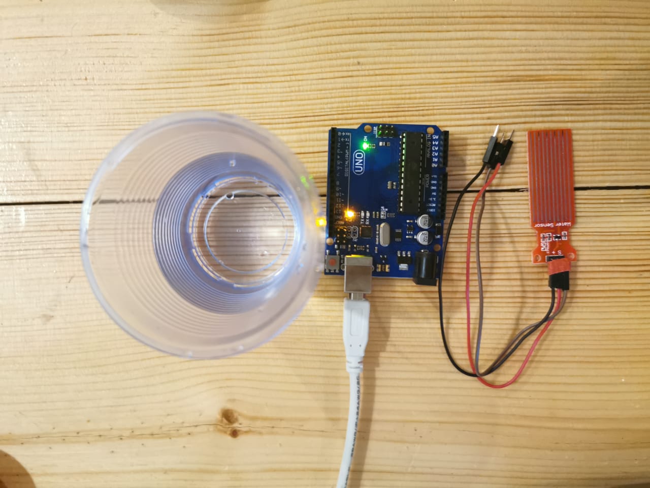
Electronices components: