Embedded Programming
Learning outcomes:
Identify relevant information in a microcontroller datasheet.
Implement programming protocols.
Individual assignment:
Read the datasheet for the microcontroller you are programming.
Program the board you have made to do something, with as many different programming languages and programming environments as possible.
Group assignment:
Compare the performance and development workflows for different microcontroller families.
Document your work (in a group or individually).
This week I will read the datasheet for the microcontroller I had design it in Electronics Design week then program the board I had made to do something, with as many different programming languages and programming environments as possible.
But Like many labs around the world, our lab close after the last session due to the COVID-19 pandemic, I could not mill my PCB, so I will not be able to use my own attiny44A board that I designed. Instead of that, I got an entry permit for the college, I went there and took my electronics kits and some sensors, I will be using the Arduino Uno ATmega328 controller. But I will try to simulate the connection between attiny44A microcontroller and Arduino by using Tinkercad.
let us discover more about microcontrollers and datasheets.
What is Datasheet?
A datasheet lists out all the features of the product including both technical and nontechnical details and explains them in an easily understandable language. It is your complete encyclopedia on a part. A good datasheet will tell you everything you need to know about it. Use this information. Most design errors are due to (deliberately or not) overlooking certain specifications in the datasheet. It should give you the information you need to create a working and reliable product.
How we can read Datasheet?
First thing I googled how we can read Datasheet? I spend all the afternoon trying to understand that I have read many articles and watch videos that can explain what is the datasheet for the microcontrollers? It’s really a huge document with a lot of information, about each tiny thing in this tiny ship! It is really like the HEART and BRAIN! It is done everything from A-Z for most circuits. I was looking for our circuit that I couldn’t fabricate it, because of Corona pandemic, next I’ll write and post some of the information that I read about it. It Is a collection of electronic components resistors, transistors, capacitors, etc.all stuffed into a tiny chip, and connected together to achieve a common goal. The microcontroller also has additional elements such as RAM for data storage, read-only memory for program storage, flash memory for permanent data storage, and other devices. There are a dozen different vendors who manufacture microcontrollers. Few among them are Intel (8051), Atmel (AVR), Microchip Technology (PIC), Hitachi, Motorola, etc. We will discuss two such microcontrollers that have created waves recently; AVR and PIC.
To read more: AVR vs.PIC
Microcontrollers are used in automatic products and devices, such as car engine systems, remote controls, machines, appliances, power tools, and toys. These are called embedded systems. Microcontrollers can also be found at work in solar power and energy harvesting, anti-lock braking systems in cars, and have many uses in the medical field as well. These first microcontrollers combined different types of computer memory in one unit.
After people began to see how useful they were, microcontrollers were constantly being upgraded, with people trying to find new ways to make them better.
The Cost was reduced over time and by the early 2000s, microcontrollers were widely used across the world.
To read more: Intro To Electronics
How and who was fabricate the microcontrollers?
It is a long press to produce these small ships! I'm really surprised this is my first time thinking about it, and I kept searching to know more about this invention.
I enjoy reading and learning about the history of things around me and who was the first one invented it.
It was during 1970 and 1971 when Intel was working on inventing the world's first microprocessor, that Gary Boone of Texas Instruments was working on quite a similar concept and invented the microcontroller.
I will let you enjoy this small story about what is inside the microcontroller starting from the sand! yes, it is made of sand after many steps. You must see this it is AMAZING!
Microcontrolles Fabricationr
Individual assignment
I will focus on the AVR microcontroller because I used it in the last assignment and also I will keep using it in this assignment.
The AVR microcontroller architecture was developed by Atmel in 1996. It is based on the Harvard microcontroller architecture. It was one of the first microcontroller families to use on-chip flash memory for program storage, as opposed to one-time programmable ROM, EPROM, or EEPROM used by other microcontrollers at the time. Every AVR has some input/output ports. The port has up to 8 physical pins on its package. Every pin can be configured as input or output. If a pin is used for input, it can turn on built-in pull-up resistors through register PORTx. If a pin is configured as an output, it can handle up to 40mA of load per pin and max 100mA for all pins on the port.
To understand more about it visit this the link below it’s useful. History of Microcontroller
Attiny 44/85 microcontroller
It is the keystone of the circuit, the below picture explained the pin configurations.

Atitny44/85 Datasheet
Mapping of theATTiny44/85 pins courtesy:

Programming Attiny 44/85 microcontroller by using Tinkercad programming environment
Tinkercad is an environment there are a variety of components you can add to your design. You’ll find an integrated code editor and a debugger. It allows you to Program and simulate your Prototype with electronic components, completely within the browser, before building them in real. You can even get to the serial monitor, all in your browser with no actual Arduino hardware. you can simulate Arduino with a debugger that could come in handy if you care about the circuit simulations. What did I do? I connected attiny85 with a potentiometer to control the servo motor. I tried to do this by Tinkercad in a simple way. I opened Tinkercad with Internet explore browser, it wroked fine with it rather than google chrome. I already had account, you can sign in with your Autodesk or Goole account.
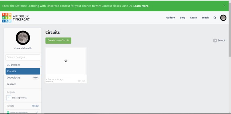
The workspace where you can assmble the components and code:
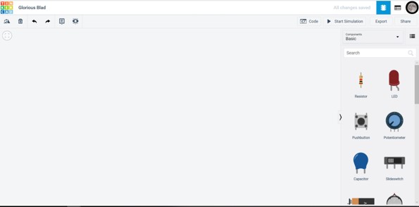
First I insert the components:
- Attiny85 microcontroller
- 10K Potentiometer
- Servo motor
- 6-9V Battery
- Bredbored
- The power wire is typically red, and should be connected to the power of Attiny 85.
- Ground wire is typically black and should be connected the ground.
- Signal wire is orange and should conncted to a digital pin on the 0.
- The first pin -trimnal1- conncted to the ground of Attiny85.
- The secound pin -wiper wiper, it acts as a variable resistor or rheostat- conncted analog input A1 of Attiny85.
- The thired pin -trimnal 2- conncted to the power of Attiny85
- The Volt conncted to the positive in the battery.
- The ground to the negtive in the battery.
- "#include" is used to include outside libraries in your sketch. This gives the programmer access to a large group of standard C libraries (groups of pre-made functions), and also libraries written especially for Arduino.
- "SoftwareServo.h" library is one of the libraries that will drive particular servos on all of XMC's pins simultaneously.
Libraries provide extra functionality for use in sketches, e.g. working with hardware or manipulating data. - "#define" pinName pinNumber.A convenient way to define the used pins. That allows the programmer to give a name to a constant value before the program is compiled.
- "Void" is the type of the expected output of the function,that in this case is none,loop() is the function that will be executed. The loop function is a special function,because it will run infinitely, restarting after each end.
- "Loop()" is the function that will be executed. The loop function is a special function,because it will run infinitely, restarting after each end.
- "Setup()" function is called when a sketch starts. Use it to initialize variables, pin modes, start using libraries, etc.
- "AnalogRead()" reads the value from the specified analog pin. It will map input voltages between 0 and the operating voltage(5V or 3.3V) into integer values between 0 and 1023.
- "AnalogWrite" to update the status of analog pins and also used to address the PWM pins on the board.
The PWM pins are 8-bit pins, Pulse Width Modulation, or PWM, is a technique for getting analog results with digital means. Digital control is used to create a square wave, a signal switched between on and off. This on-off pattern can simulate voltages in between full on (5 Volts) and off (0 Volts). - "Delay" pauses the program for the amount of time (in milliseconds) specified as parameter. (There are 1000 milliseconds in a second.)
arduino-cheatsheet
Arduino language
Code File:
ATmega328 microcontroller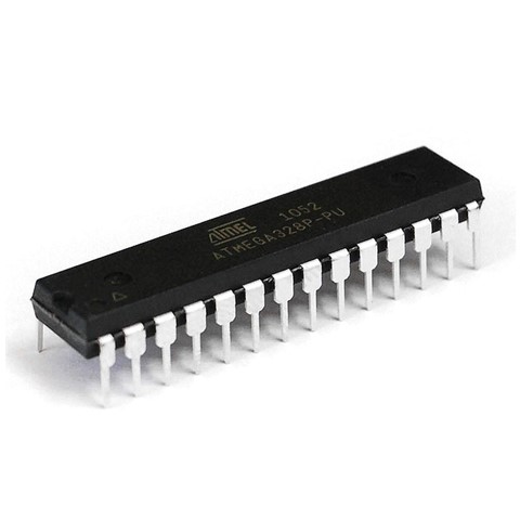
My microcontroller is ATMEGA328P-PU from Microchip Technology is high performance, low power controller from Microchip.I will use it with the Arduino Uno since I can't mill my PCB as I metioned before. ATMEGA328P is an 8-bit microcontroller based on AVR RISC architecture.It is the most popular of all AVR controllers as it is used in ARDUINO boards.
Mapping of theATTiny44/85 pins courtesy:
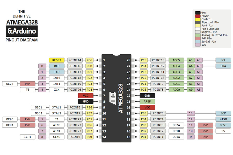
ATmega328P_Datasheet
ATMEGA328P-PU
Atmega328p Pinout Features Datasheet
The first thing to know is the difference between Pins and Ports. - A Pin is the physical metal part coming from the chip and the number ascribed to it given its location that chip.
- A Port refers to a Pin given its function within a register.
- A register is a location in a store of data, used for a specific purpose and with quick access time.
- Arduino.
- USB Cable.
- Jumper wires
- LED.
- 220 ohm resistor.
- Potentiometer.
- The first pin -trimnal1- conncted to the ground of Arduino.
- The secound pin -wiper wiper, it acts as a variable resistor or rheostat- conncted analog input A0.
- The thired pin -trimnal 2- conncted to 5V.
- Potentiometer_led
- The Hydration bottel PCB Circuit

Connection of the components:

Based on I/O pins in Attiny85 I conncted the componnetes as shows below, by add line -wiers-. As Atitny85/44 Datasheet there are I/O pin.
Servo motor have three wires: power, ground, and signal.
Potentiometer is a simple knob that provides a variable resistance, which we can read into the microcontrollers board as an analog value. It has 3 pins.
Two terminals (the blue and green) are connected to a resistive element and the third terminal (the black one) is connected to an adjustable wiper.
The potentiometer can work as a rheostat (variable resistor) or as a voltage divider.
Atitny85 to the power source:
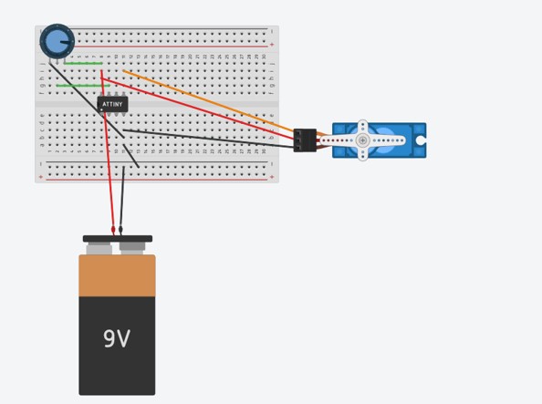
The connctetion completed.
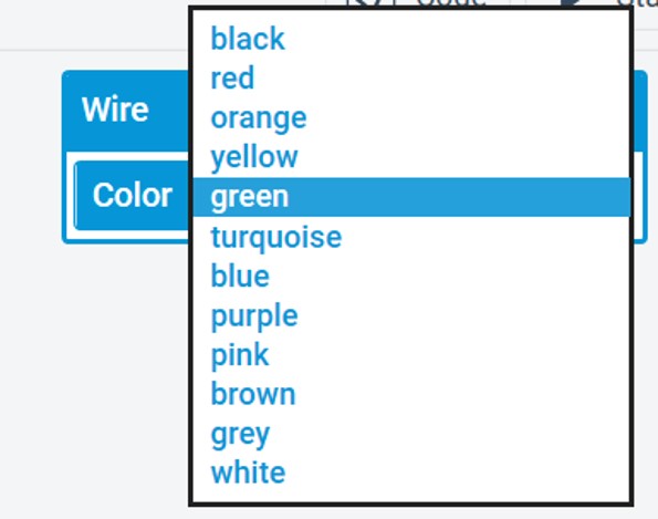
You can change the wires colors to distinguish them, by click on the wire then it will pop up a colors tab.

To rotate or delet one component or more, syou can use the simple tool bar up of the workspace, click on the component then click on the icon.
Coding: I designed a circuit with Attiny85 microcontroller to control the servomotor by using the potentiometer.
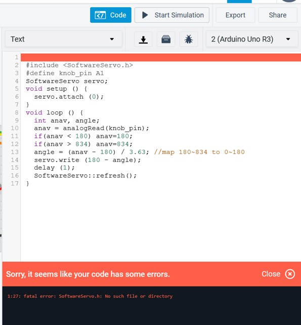
After that I uploaded the code it was not sucssed from the first time, so I used the debugger - the bug icon-. I guess because of SoftwareServo.h library was missing.
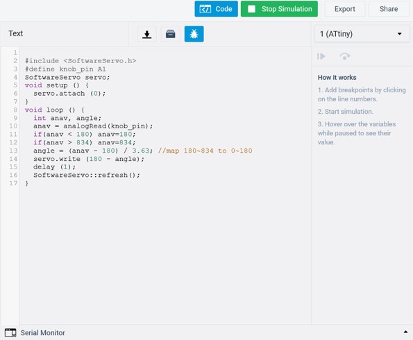
First I tried 6V but it didn't worked.
I tried 9V and it workrd.
Reading the code:
Arduino programming language can be divided in three main parts: functions, values (variables and constants), and structure.
Functions For controlling the Arduino board and performing computations.
values Value is the representation of some entity that can be manipulated by a program, in Arduino values are variables and constants.
A variable is a value that can change, depending on conditions or on information passed to the program.
A constant is a fixed value, that cannot be altered by the program during normal execution. For example X+4=7 the 4 and 7 are constants.
Structure is used to represent information about something more complicated than a single number, character, or boolean can do.
The elements of Arduino (C++) code.
AVR architecture

In order to maximize performance and parallelism, the AVR uses a Harvard architecture with separate memories and buses for program and data. Instructions in the program memory are executed with a single level pipelining.
Pin Configurations

Pin Descriptions
To know which ports are used as input/output (I/O) pins.

Data Direction Register
The data direction register, is 8 bits wide, and is programmed to select whether each individual input/output pin is configured as an input or an output. For more about AVR

AVR Memories:
Flash Program Memory In-System Reprogrammable Flash Program Memory The ATmega328P contains 32Kbytes on-chip in-system reprogrammable flash memory for program storage. Since all AVR instructions are 16 or 32 bits wide, the flash is organized as 16K 16. For software security, the flash program memory space is divided into two sections, boot loader section and application program section in ATmega328P.
SRAM Data Memory SRAM (Static Random Access Memory) is made up of CMOS technology and uses six transistors. Its construction is comprised of two cross-coupled inverters to store data (binary) similar to flip-flops and extra two transistors for access control. It is relatively faster than other RAM types such as DRAM. It consumes less power. SRAM can hold the data as long as power is supplied to it.
EEPROM stands for electrically erasable programmable read-only memory and is a type of non-volatile memory used in computers, integrated in microcontrollers for smart cards and remote keyless systems, and other electronic devices to store relatively small amounts of data but allowing individual bytes to be erased and reprogrammed.
EEPROMs are organized as arrays of floating-gate transistors. It can be programmed and erased in-circuit, by applying special programming signals. Stack Pointer The stack is mainly used for storing temporary data, for storing local variables and for storing return addresses after interrupts and subroutine calls.
Programming ATmega328P microcontroller by using Arudino IDE programming environment
What did I do? I connected the ATmega328P microcontroller IN Arduino UNO to control LED brightness by using a potentiometer. How? by gradually changing electrical signal from turning the potentiometer with Arduino's analog inputs, located on the board from the digital i/o (input/output) pins. These special analog pins are connected to the Arduino's analog to digital converter, which converts an incoming analog signal between 0V and 5V into a range of numbers from 0-1023 (zero counts as a value). I used the Arduino IDE programming environment. The Arduino Integrated Development Environment (IDE) is the main text editing program used for Arduino programming. It is where you’ll be typing up your code before uploading it to the board you want to program. Arduino code is referred to as sketches. The Arduino IDE supports the languages C and C++ using special rules of code structuring. The Arduino IDE supplies a software library from the Wiring project, which provides many common input and output procedures.
First I collcted the components:
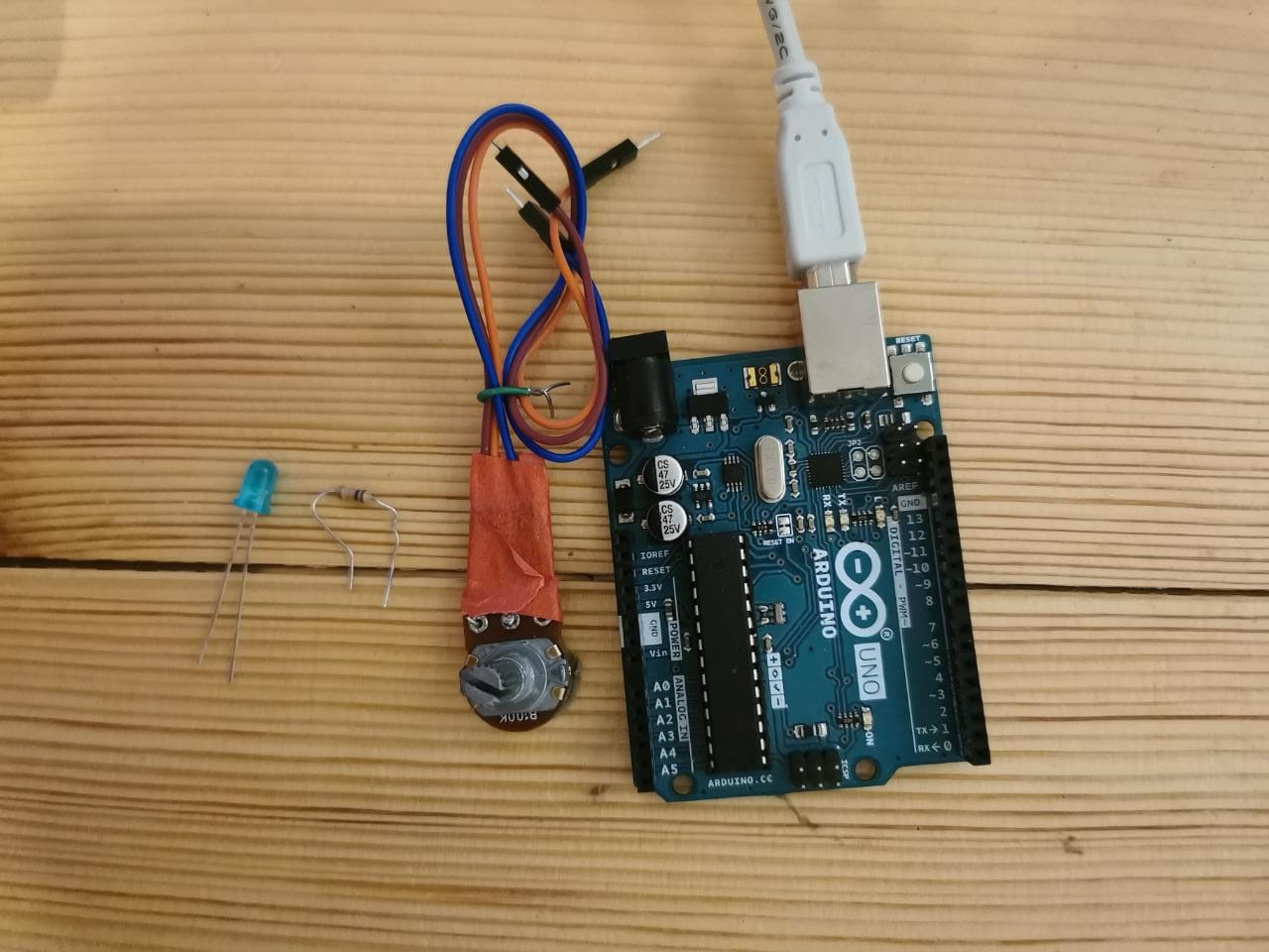
Connction

Connction of the LED: I conncted the Long positive leg to the output from the resistor that conncted to pin 8.the shortleg negtive to GND.
Connction of the potentiometer:
The potentiometer can work as a rheostat (variable resistor) or as a voltage divider.
I downloaded the Arduino IDE from the officail website.
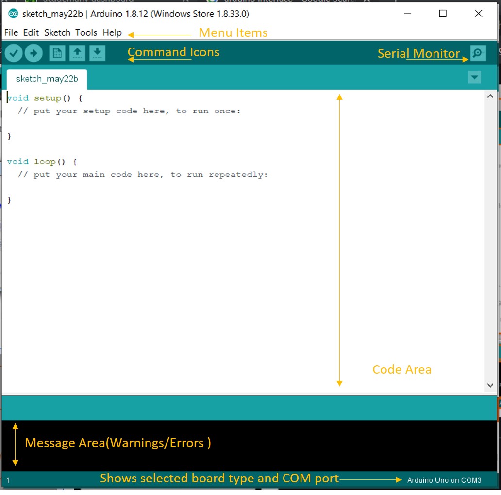
Arduino Integrated Development Environment (IDE) interface.
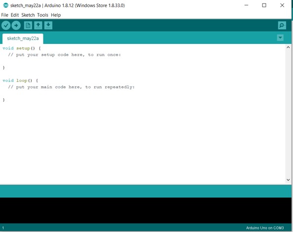
I Deleted every thing in the workfram.

I conncted my Arduino board to my lap top, then I clicked on tools the I chose my Arduino UNO board from the list.

I clicked on tool again to cheked the port.
I copied the code.

The code in the text editor.

I Verified the code before uploading to my board, to check the errors.

I uploaded the code.

I saved the code after that.
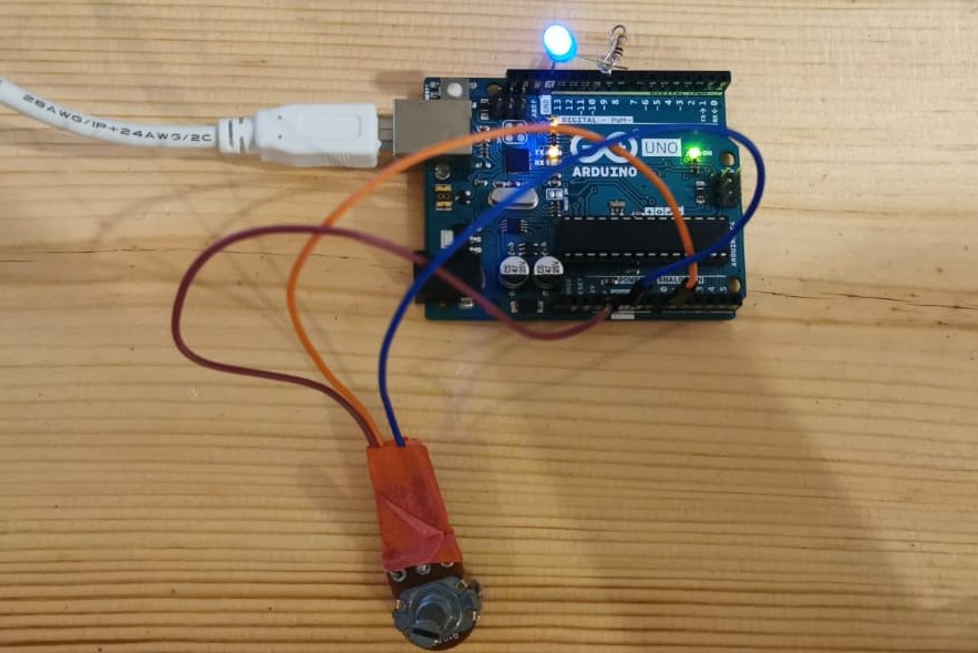
It worked, I controlled the LED gradually by potentiometer.
Code File:
Programing my boards
In this stage I will show the different codes I did to manage the electronics for this project, everything was coded by using Arduino IDE.
Based on the Attiny 44 data sheet I/O pins.
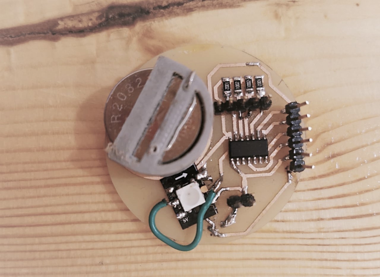
In this circiut I tryed before to program attiny digitaly by using Tinkercad on Electronics Design week. and as a guied I followed the step on this link.
Code
In this code, I added Adafruit_NeoPixel.h library for controlling single-wire-based LED pixels. each water level has a different analog pin, each level has a different color. I was thinking of using jumper wires with different levels, or copper tape, but I took the advice to make a piece of PCB board with etching different levels, and it works.
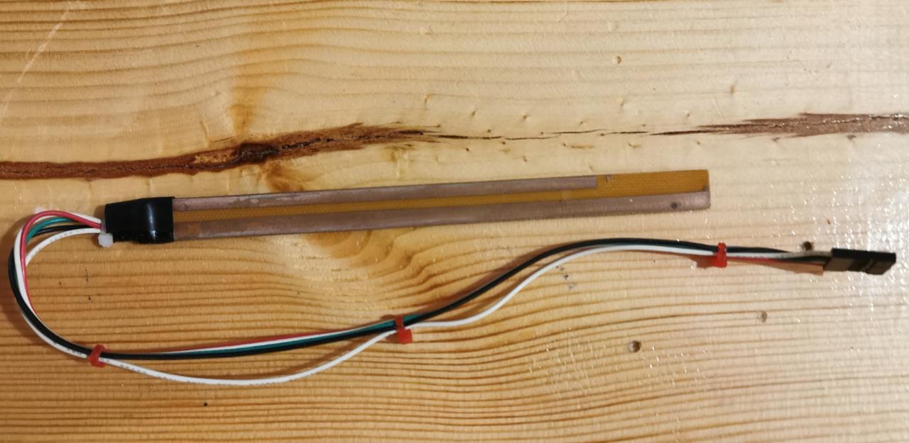
The sensor after atching and soldering the pcb boread.
Testing the circiuts
Haydration smart water bottle