Electronics Design
Characterize the design rules for your PCB production process: document feeds, speeds, plunge rate, depth of cut (traces and outline) and tooling. document your work (in a group or individually).
Individual assignment:
Make an in-circuit programmer by milling and stuffing the PCB, test it, then optionally try other PCB fabrication process.
Learning outcomes:
Described the process of milling, stuffing, de-bugging and programming.
Demonstrate correct workflows and identify areas for improvement if required.
Starting with Eagle!
I have started this week by downloading Eagle software from Autodesk for the first time it is a PCB designing tool, It was recommended by the instructor. New knowledge for this week. I will make an in-circuit programmer from scratch. As always in our weakly meeting Eng. Yousef AlSenwar explains to us the basics about building circuits, first I download Eagle and activated. What I mostly like about Eagle the graphics, it is easy-to-use tools, and vibrant community there are many youtube tutorials explain everything step by step. I followed one tutorial to know more about routing, add parts, how to label and many other things. I startd with a basic circuit to practice before starting with the assignment. I learned more about connctions, how can I placing the components in a schematic and connecting them to each other, routing the traces between the components and laying out the board
Individual assignment designing in-circuit programmer:
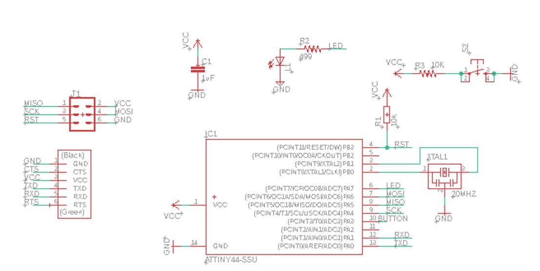
The Hydration bottelPCB Circuit
In this project I designed the board by using eagle by adding the below compounentes:
- 1x Attiny 44
- 4x Resistor 10K
- 13x Pin holder
- 1x RGB LED
- 1x terminal pin holder
Eagle Workflow:
Opening Eagle
I Created a new project and renamed it, then I clicked on it to creat a new schematic file to build my circuit by adding the electronices components.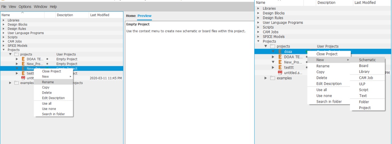
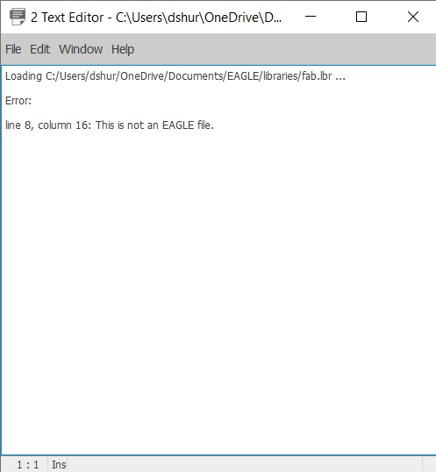
Then I downloaded the Fab.Lbr from the Fab Acadmey tutorial. It is library icluding electronices components to bulid the frist circuit. I have faced a problem while adding the fab.lbr to the eagle file, I tried a couple of times but then I searched for the problem., (Error message: line 8, column 16: This is not EAGLE file.)
How to solve:
After reading many sulotions what I did, I changed the name of fab.lbr.
I clicked on library directly on the top > create managed library > I chose the library file then counited the steps and finally it’s in the libraries list.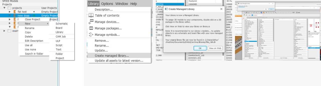
Make sure fab.lbr is added and "in use“. I renamed it with 00 in the being to shows in the top always.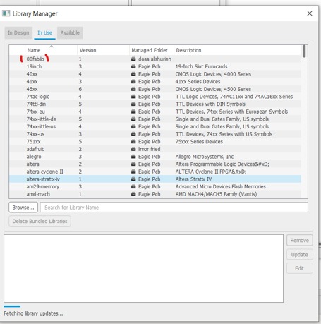
How to Connect the Components?
There are two ways to connect components in a schematic:- You can connect the components with a wire (also called a "net" in Eagle). This may make connections obvious at first but can get really messy quickly as nets cross over each other.
- You can also name the nets attached to components that need to be connected by naming them with the same name.
Commands toolbar I used:
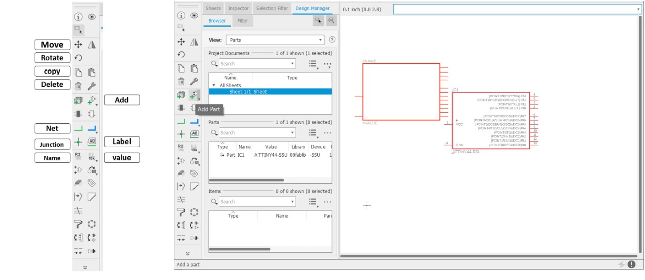
- Move tool to move components and Lines.
- Rotate tool to rotate components after simmering the (+) symbols.
- Copy tool to duplicate components
- Delete tool to delete components, extra text, lines also.
- ADD tool to Add components.
- Net to add green wire representing connectivity, which is exactly its purpose.
- Junction to draw a connection dot at the intersection of nets which are to be connected to each other, Junction points may be placed only on a net. If placed on the intersection of different.
- Label tool After naming a net, you should use the Label tool to add a text label.
- Name tool is used to store part names.
- Value tool is used to store part value.
How To add & connect components in the schematic?
Select the "add icon from the toolbar as show below: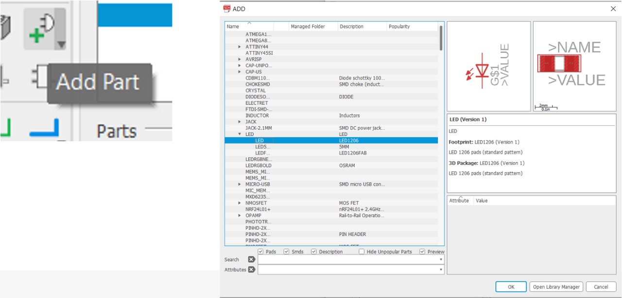
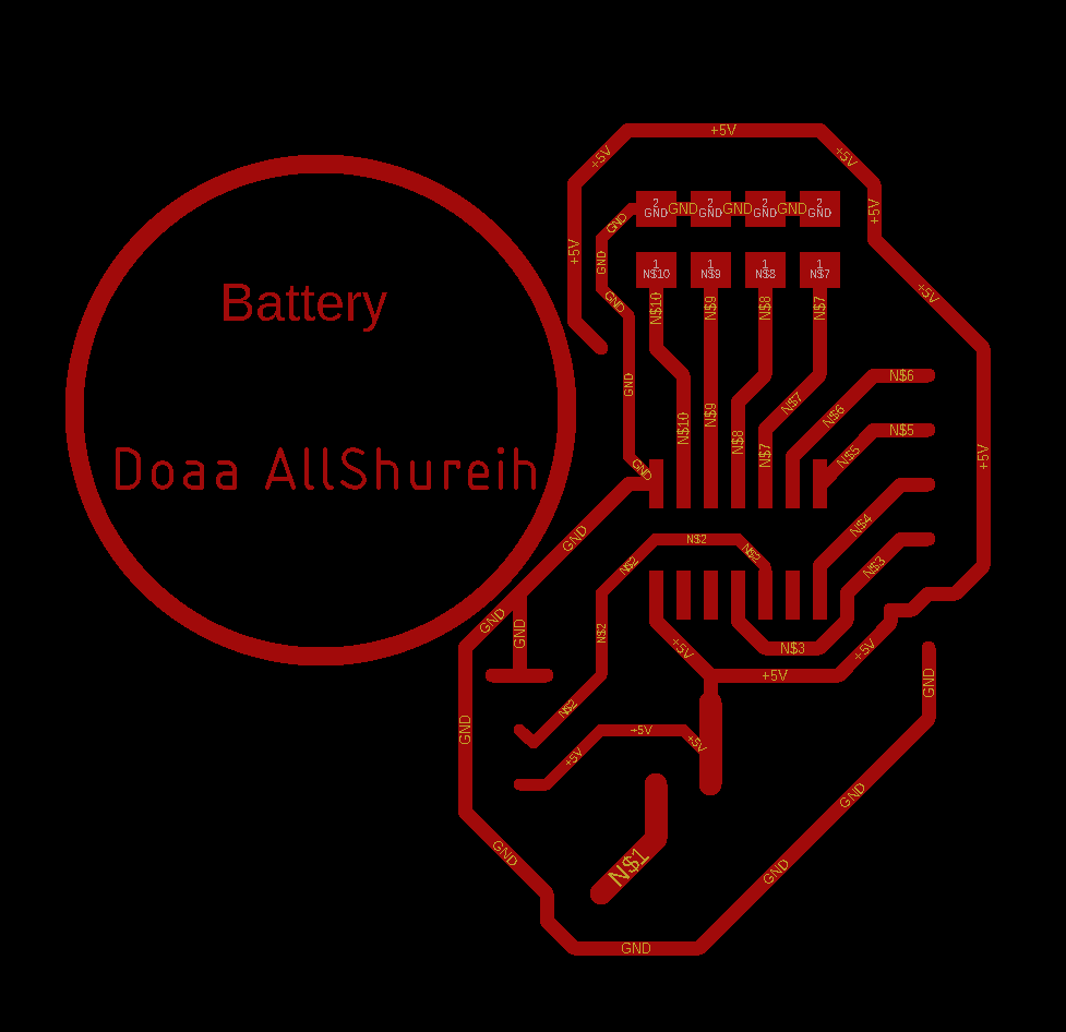
Route traces on aboard.- Switch to the board view.
- Go to the top menu > File > switch to board.
Befor routing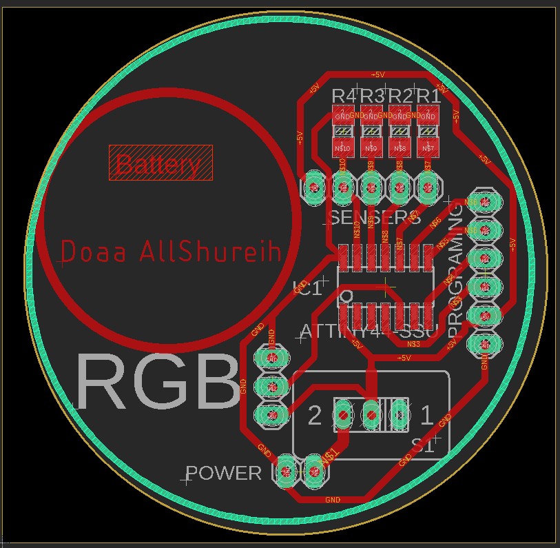
After routing
Exporting the board design for milling Prepear board for milling:- From layers menu in the top toolbar
- Hide all the layers, then show only Top layer
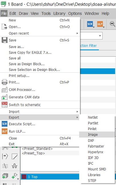
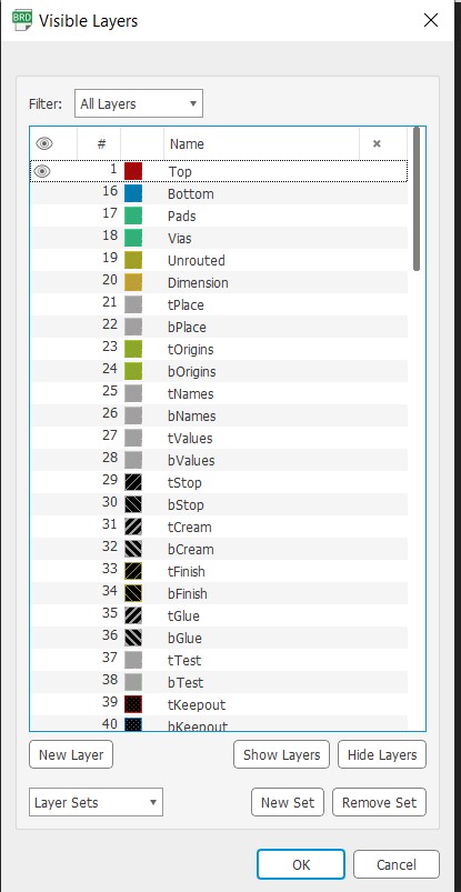
I hided all the layers and kept only the top layer.
Exporte design as .PNG
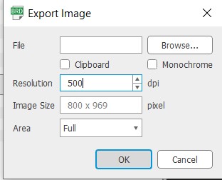
- Go to file > export > image
- Make sure the resolution 500 and do check the monochrome
- Repeat the same steps to save the frame separately it is mention as dimension.
Ready to conver to SVG
Make sure to crop the mage before use it , for better resolution. When I uploaded before cropping the image, the tracing was not as it should be.
The picture in the right after I do the crop by illustrator and you can crop it with the image editor also.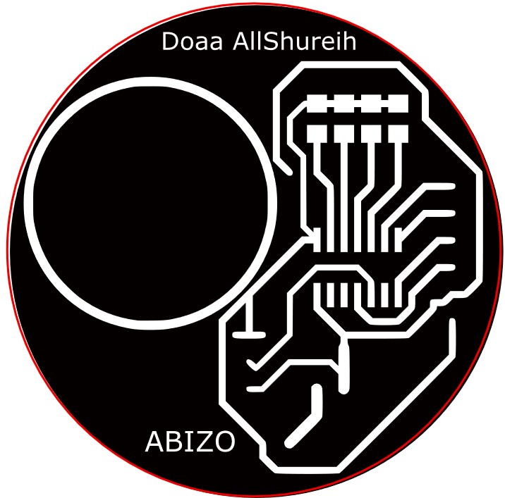
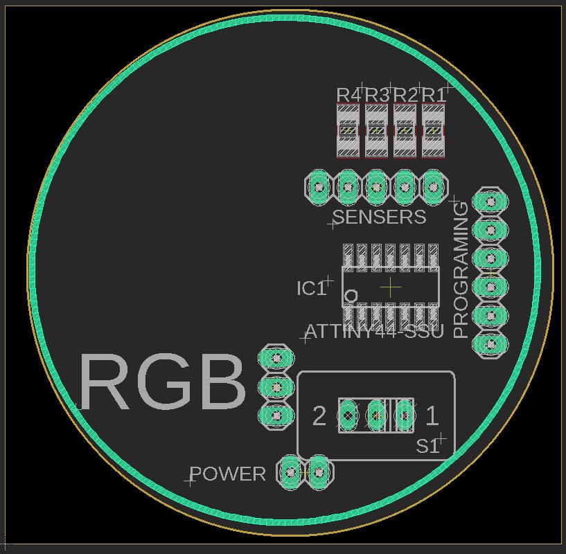
PCB Fabrication
After I exported the circiut to .png, I used inkscape to traced it then saved it as svg. By using Easel I milled my board, with the follwing setting:
Milling - Bit : 1/64 in = 0.015 in, but I prefer 0.012 in
- Depth : 0.2 mm
- Depth per pass : 0.1 mm
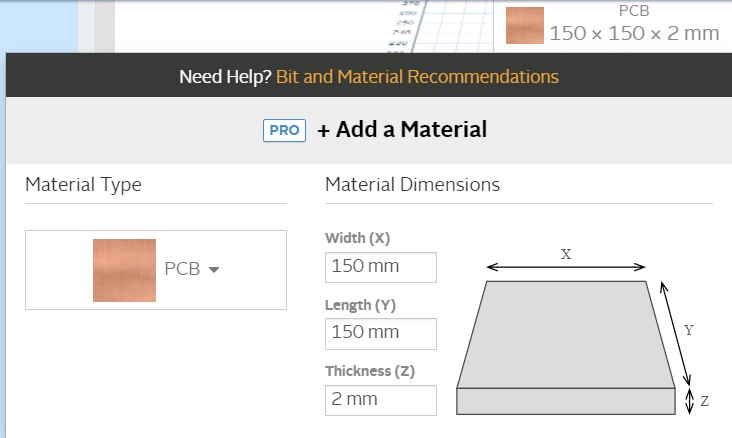
PCB coper sheet size and thickness.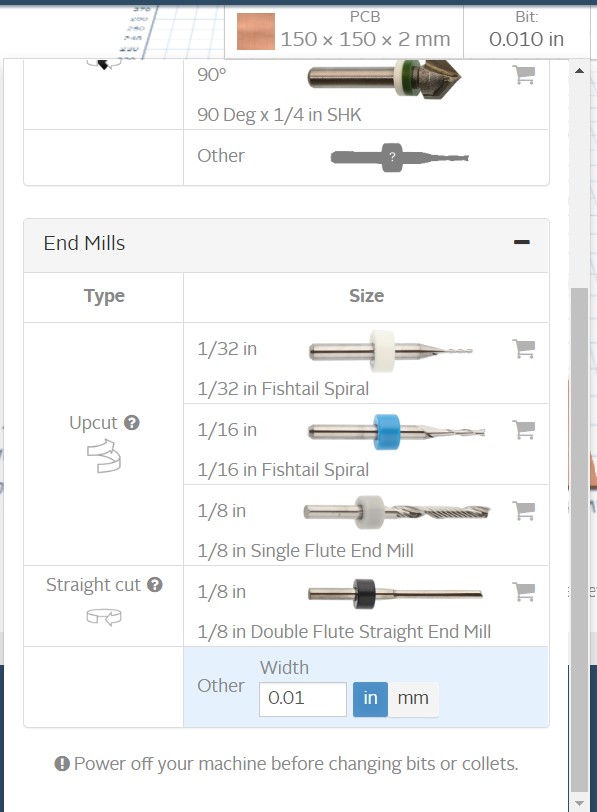
Milling bit.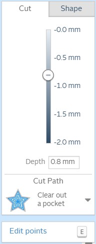
PCB milling depth.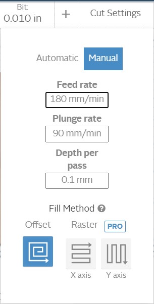
Setting for perfect milling by using Carvey machine.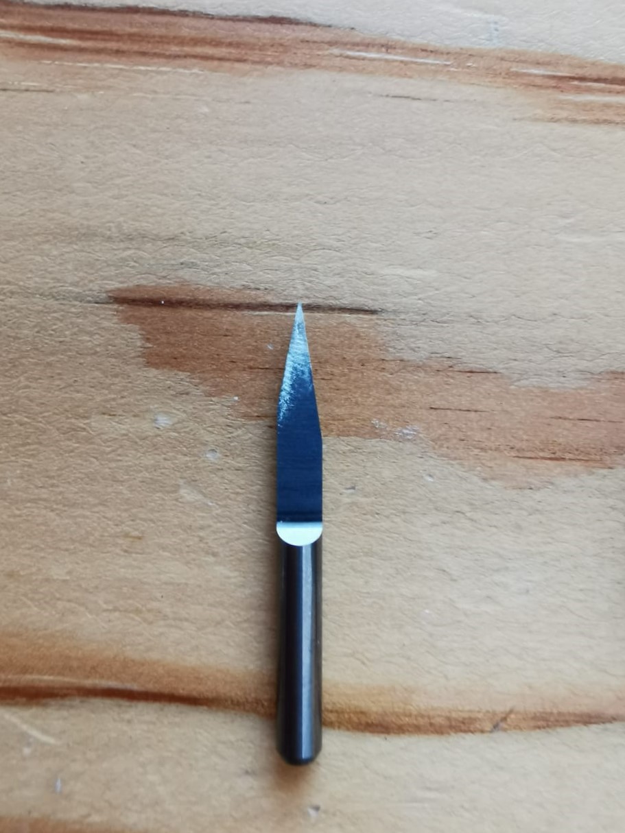
The milling bit. 1/64in
Outline Cutting - Bit : 1/32 in = 0.031 in
- Depth : 1.8 mm
- Depth per pass : 0.3 mm
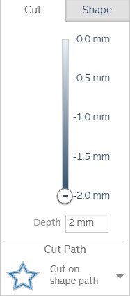
PCB cutting depth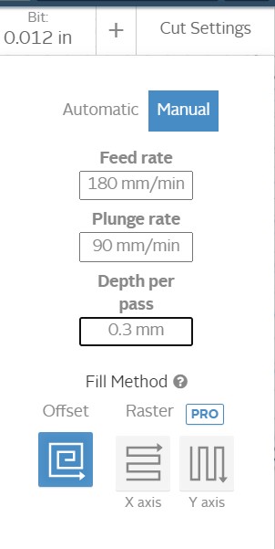
PCB cutting setting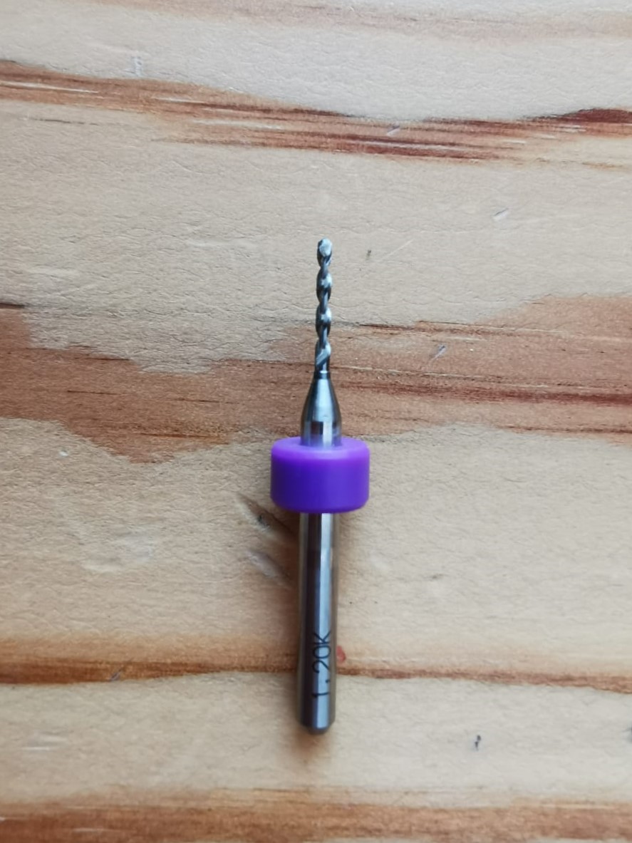
Cutting bit 1/32 in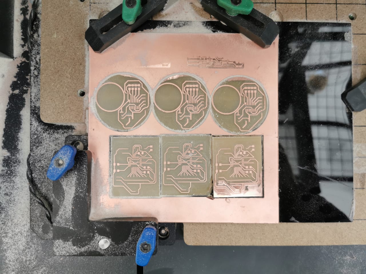
Final result
Soldering
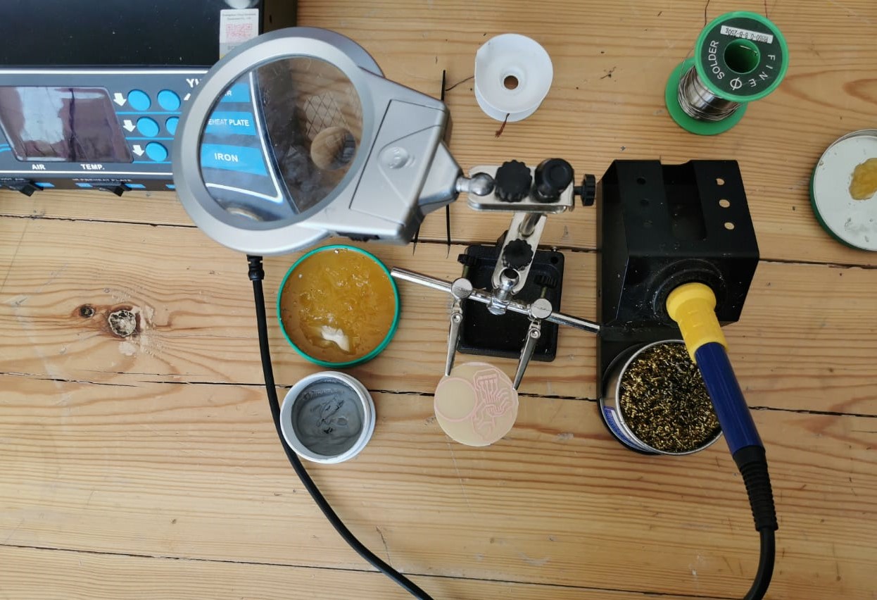
I used flux, soldering wire, and in some parts soldering tape. and for more control I used tweezers.
The Hydration bottel PCB Circuit
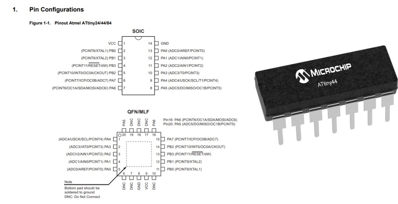
Based on the Attiny 44 data sheet I/O pins.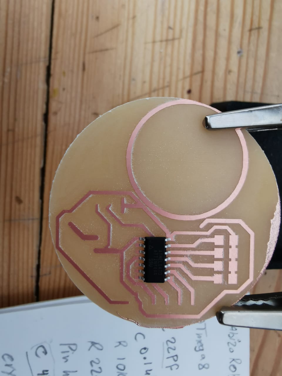
Always start with the microcontroller, I but some flux and a little bit of soldering wire in the tip of the soldering iron then I passed on the pins. I completed the soldering but I faced a problem with battery holder, it was bigger than I thought, so I used 3d printed holder I used before it works fine.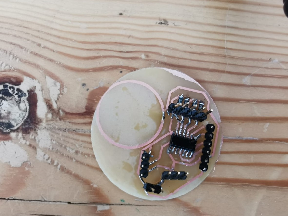
Almost done!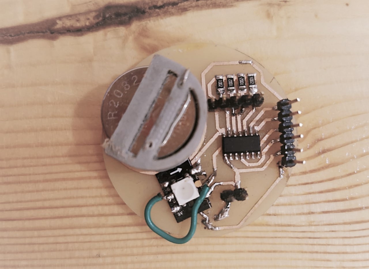
It's finlay ready.
Programing
In this stage I will show the different codes I did to manage the electronics for this project, everything was coded by using Arduino IDE. First I connected the ATTiny44 to the Arduino based on the Attiny 44 data sheet I/O pins.- Connect the ATtiny44 Pin 1 to 5 volts (VCC)
- Connect the ATtiny44 Pin 14 to ground.
- RESET: Connect the ATtiny44 Pin 4 (Reset) to Arduino Pin 10.
- MOSI: Connect the ATtiny44 Pin 7 to Arduino Pin 11.
- MISO: Connect the ATtiny44 Pin 8 to Arduino Pin 12.
- CLOCK: Connect the ATTiny44 Pin 9 to Arduino Pin 13
Test the circuit by flash an LED connected to Pin 5
Bootlaoder It is a special piece of code that is executed at every reset of the microcontroller and that looks for a sketch to be uploaded from the serial/USB port using a specific protocol and speed. If no connection is detected, the execution is passed to the code of your sketch. By default, the ATtiny’s run at 1 MHz. You can configure them to run at 8 MHz instead, which is useful for faster baud rates with the SoftwareSerial library or for faster computation in general. To do so, once you have the microcontroller connected, select “8 MHz (Internal)” from the Tools > Clock menu.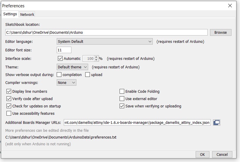
First open File > Preferences. Then, at the bottom you see "Additional Boards Manager URLs" you want to copy and paste "https://raw.githubusercontent.com/damellis/attiny/ide-1.6.x-boards-manager/package_damellis_attiny_index.json". Now click OK.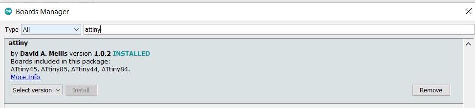
After adding Attiny44 from the library library Tools > Board > Board Manager.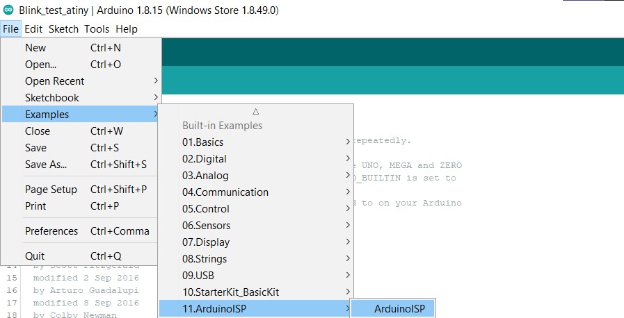
File > Examples > ArduinoISP. Open the sketch and upload it to your Arduino. Select ATtiny from Tools > Board.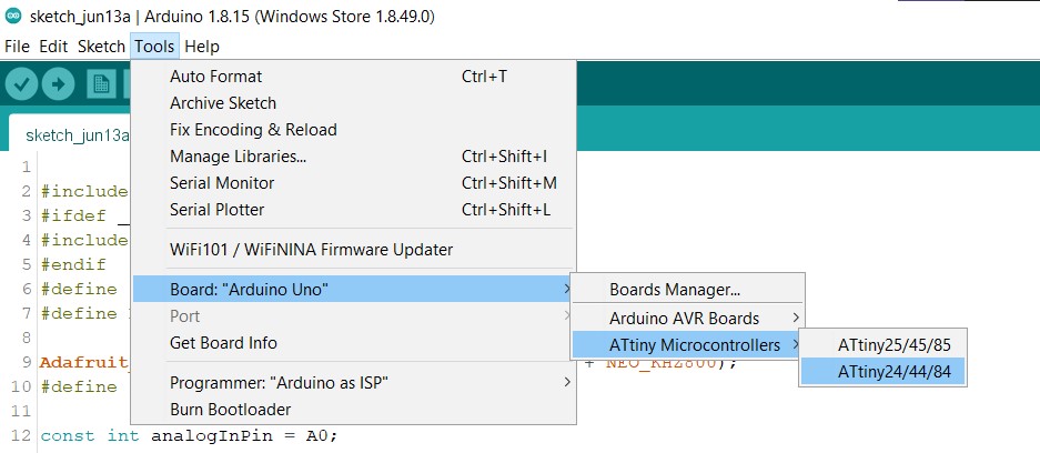
Select the specific ATtiny you are using (44/45/84/85) from Tools > Processor.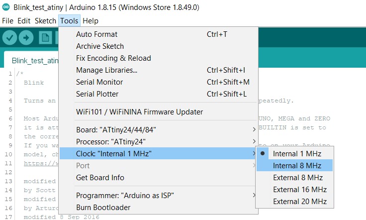
Next select "8 MHz (Internal)" from Tools > Clock.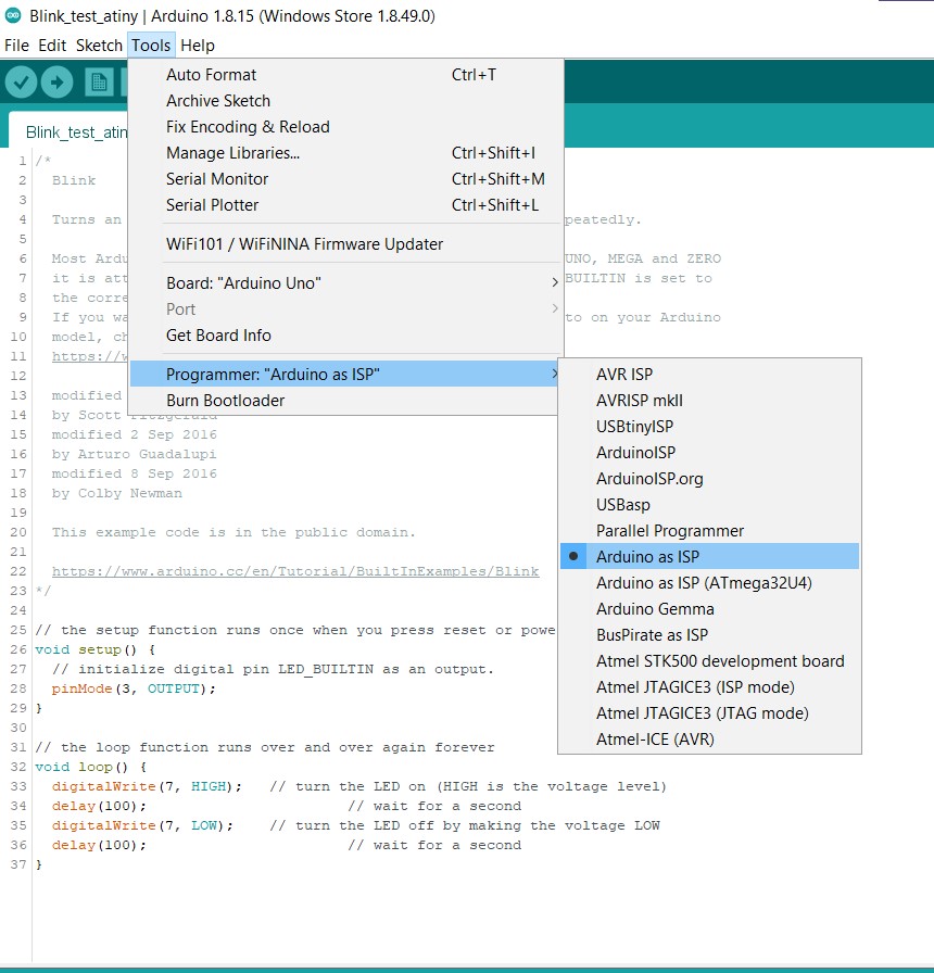
Now upload the code to your bored from "Arduino as ISP" under Tools > Programmer.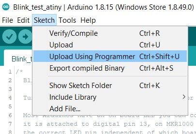
Form sketch and use upload using Programmer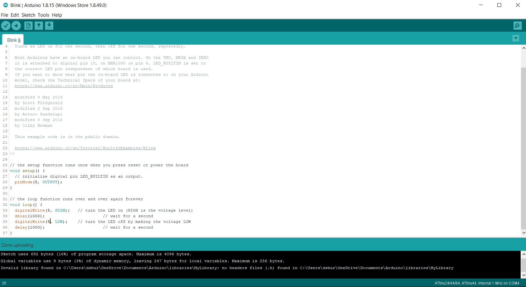
Done uploading!
The testing code
The result
PCB files: - Hydration water bottle SCH
- Hydration water bottle BRD
Group assigment