Output Devices
Demonstrate workflows used in controlling an output device(s) with MCU board you have designed.
Group assignment:
Measure the power consumption of an output device.
Document your work (in a group or individually).
Individual assignment:
Add an output device to a microcontroller board you've designed and program it to do something.
This week we will complete desinging circuits with microcontrollers, in this time I will add an output device to my board in Embedded Programming week. For physical testing instade of that I 'll use Arduino UNO, and Microbit, to prepare my circuits for my final project.
Group assignment:
In this assignment I will measure the power consumption of an output device. The power is measure of how quickly energy is used and is measured in watts.
How we can determined the power?
By Following Ohm's law formula: Power (watts) = Voltage (volts) x I current (amps).
But now the power can be determined by measuring the voltage and current on a device using a digital multimeter.
What is a Digital Multimeter?
A multimeter measures the key electronic characteristics of a circuit: voltage, current and resistance. Two points at different locations on a circuit have a difference in electrical potential between them, which is described as the voltage difference or just voltage between the points. Multimeters use the relationship between these quantities described by Ohm’s law to measure them for any circuit. to do that connect the measurement leads to the multimeter. These are supplied with the multimeter and there should be a red lead and a black lead. Connect the red lead to the positive plug and the black lead to the negative plug.
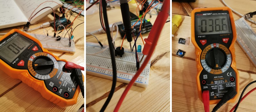
I measured the voltage of LED.
Useful links:
Individual assignment:
In this assignment I will test three sensors to prepare my final project circuits, as Prof.Niel explianed for us in the live lecture about output devises and showed us many useful examples. So I will explain more about output devices and I will do experiments step by step.
What is the Output Device?
An actuator is an output device for the conversion of supply energy into useful work. The output sngnal is controlled by the control system, and the actuator responds to the control signals via the control element. For example a display, a led, a loudspeaker, lights, LEDs, motors, speakers, displays (lcd).
In the Individual assignment I decided to tried some sensors to make the final project, i am thinking of rain sensor, Tilit sensor and accelerometer sensor, I have the rain and tilt sensors but still am searching for accelerometer sensor. I found one of the modules act like the tilt sensor with LED bulit in it is called Magic light cup module.
Magic light cup module
This module incorporates a mercury tilt switch and clear red LED. Mercury switches provide a digital signal that triggers the PWM regulator, through the program design, We can see the light like two cups filled with the effect of shuffling back and forth.
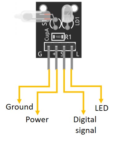
- G For the Ground is the common connection to the LED cathode and one terminal of the switch.
- S For the digital signal, is the other switch contact.
- L For the LED .
- + For the Power VCC pin connected to a 10K ohm pullup resistor connected to -S pin- of the switch.
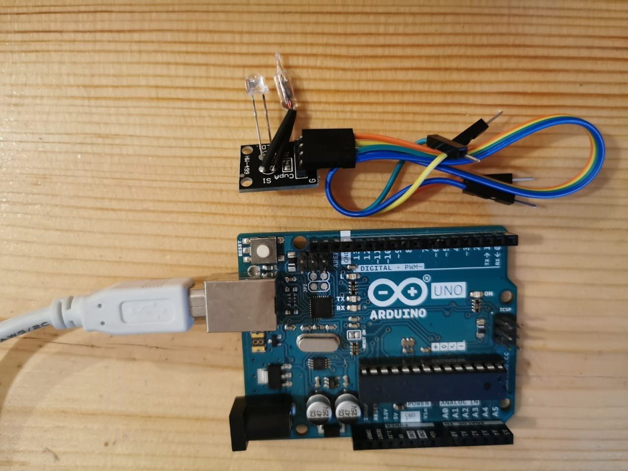
Testing the Magic Light Cup module sensor
In this project I will show you how I programmed the magic light cup module to act like alarm by using Arduion, for coding I will use Arduino IDE Programming environment, to program the sensor when the sensor switch is closed the LED is shorted and a small current flows through the resistor and switch to Gnd. When the sensor switch is open the current flows through the resistor and LED to Gnd and it lights up.
Components needed:
- Arduino UNO.
- USB cable.
- Jumper wires.
- Magic light cup medule.
Connctions of the components:
Connction of the Magic light cup medule:
- GND to GND of the Arduino.
- VCC to 5V of the Arduino.
- SIG-Signal- to digital pin 8.
- L to digital pin 5.
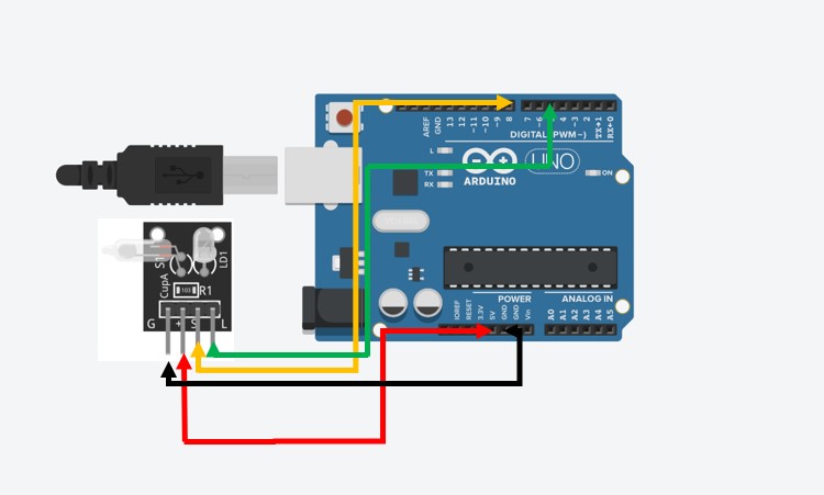
The simulation drowing of the circuit.
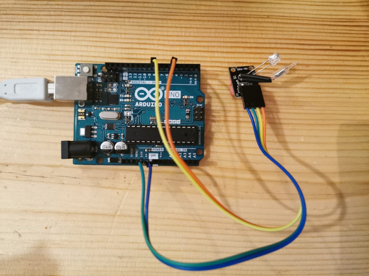
After conncted all the components.
Coding
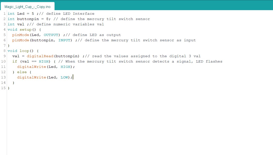
Code
I uploaded the code after verified and checked the errors.
Code Explanation:
  int Led = 5 ;//
  int buttonpin = 8; // define the mercury tilt switch sensor interface
  int val ;// define numeric variables val
First, define for the Arduino the variables the digital pins, the buttonpin pin 8 from the sensor is a switch, PIN 5 for the LED. define the numeric variable from the digital output of the sensor to the Arduino.
void setup() {
  pinMode(Led, OUTPUT) ;// define LED as output interface
  pinMode(buttonpin, INPUT) ;// read the values assigned to the digital pin
}
void loop() {
  val = digitalRead(buttonpin) ;// read the values assigned to the digital interface 3 val
  if (val == HIGH) { // When the mercury tilt switch sensor detects a signal, LED flashes
    digitalWrite(Led, HIGH);
  } else {
    digitalWrite(Led, LOW);
  }
}
Code File:
- Magic Light Cup Sensor Code
- - The first pin is for the Ground.
- + The middle pin is for the Power VCC pin it connecte to 5V in Arduino.
- S The thired pin is for the digital signal, is the other switch contact.
- Arduino UNO.
- USB cable.
- Mercury Switch Tilt Sensor
- Buzzer.
- LED
- Jumper wires.
- 220 ohm resistor
- Breadboard
- GND to GND of the Arduino.
- VCC to 5V of the Arduino.
- SIG-Signal- to digital pin 8.
- L to digital pin 4.
- Long leg the positive conncted to the 220ohm resistor to pin 2, and the short leg the negative to the ground in the breadboard.
- Connction of the Buzzer the positive conncted to pin 3, and the negative leg to the ground in the breadboard.
- Tilt Switch Sensor Code
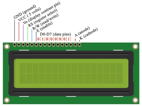
- Pin 1 GND, Ground (0v).
- Pin 2 VCC, Supply Voltage (5v).
- Pin 3 Vee, Contrast Adjustment.
- Pin 4 Register Select, (0 for Command Register, 1 for Data Register).
- Pin 5 Read/write, select (0 for write, 1 for read).
- Pin 6 Enable, Data Enable (When pulse is given, send data).
- Pins from 7-14 are Data Pins.
- Pin 15 LED+, Backlight Supply Voltage.
- Pin 16LED-,Backlight Ground.
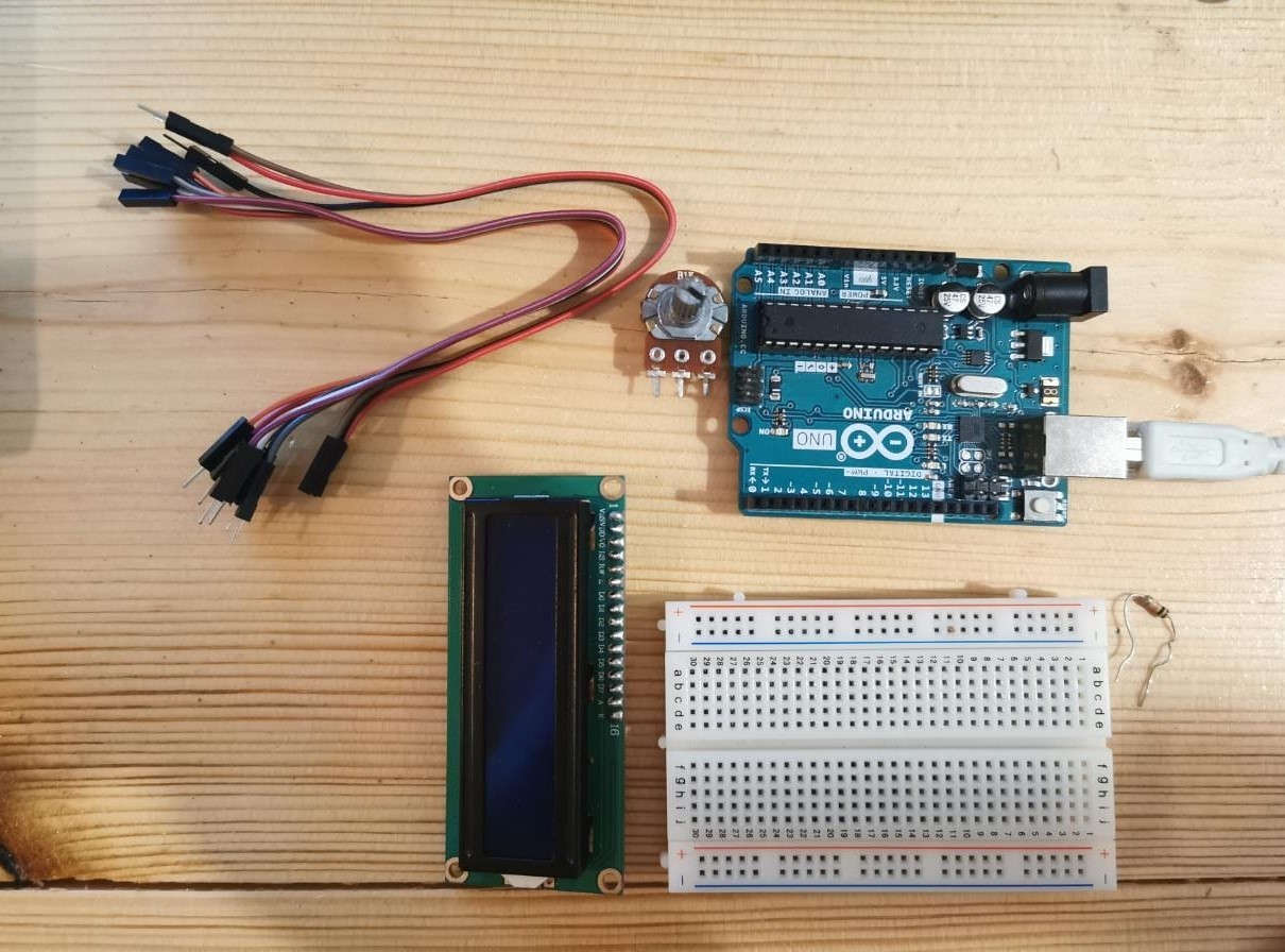
- Arduino UNO.
- USB cable.
- LCD.
- 220ohm resistor.
- Jumper wires.
- Potentiometer 10K.
- Breadboard
- LCD RS pin to digital pin 12
- LCD Enable pin to digital pin 11
- LCD D4 pin to digital pin 5
- LCD D5 pin to digital pin 4
- LCD D6 pin to digital pin 3
- LCD D7 pin to digital pin 2
- wire a 10k pot to +5V and GND, with it's wiper (output) to LCD screens VO pin (pin3).
- A 220 ohm resistor is used to power the backlight of the display, usually on pin 15 and 16 of the LCD connector.
- - The first pin is for the Ground.
- + The middle pin is for the Power VCC pin it connecte to 5V in Arduino.
- S The thired pin is for the digital signal, is the other switch contact.
- Arduino UNO.
- USB cable.
- LCD.
- DHT11.
- Jumper wires.
- Potentiometer 10K.
- Breadboard
- LCD RS pin to digital pin 12
- LCD Enable pin to digital pin 11
- LCD D4 pin to digital pin 5
- LCD D5 pin to digital pin 4
- LCD D6 pin to digital pin 3
- LCD D7 pin to digital pin 2
- wire a 10k pot to +5V and GND, with it's wiper (output) to LCD screens VO pin (pin3).
- VCC - 5V
- S - Pin 7
- GND - GND
- DHT11 Sensor
- 1x Attiny 44
- 4x Resistor 10K
- 13x Pin holder
- 1x RGB LED
- 1x terminal pin holder
Schematic Drawing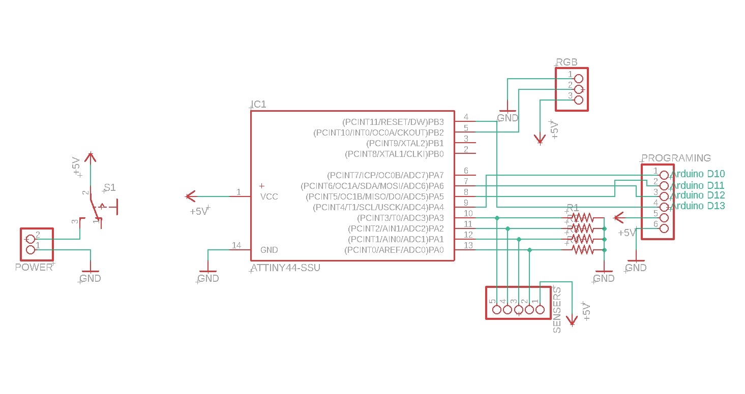
Board Drawing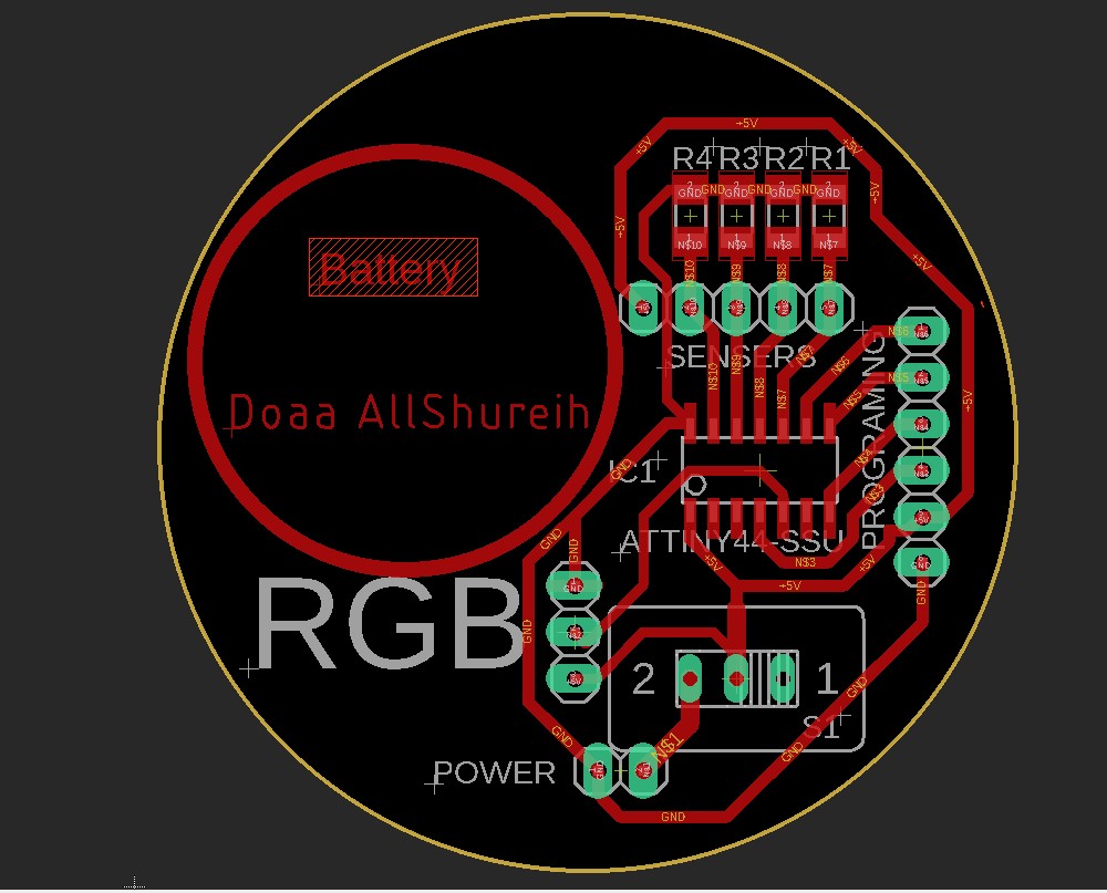
Programing
In this stage I will show the different codes I did to manage the electronics for this project, everything was coded by using Arduino IDE.
- The Hydration bottel PCB Circuit
Based on the Attiny 44 data sheet I/O pins.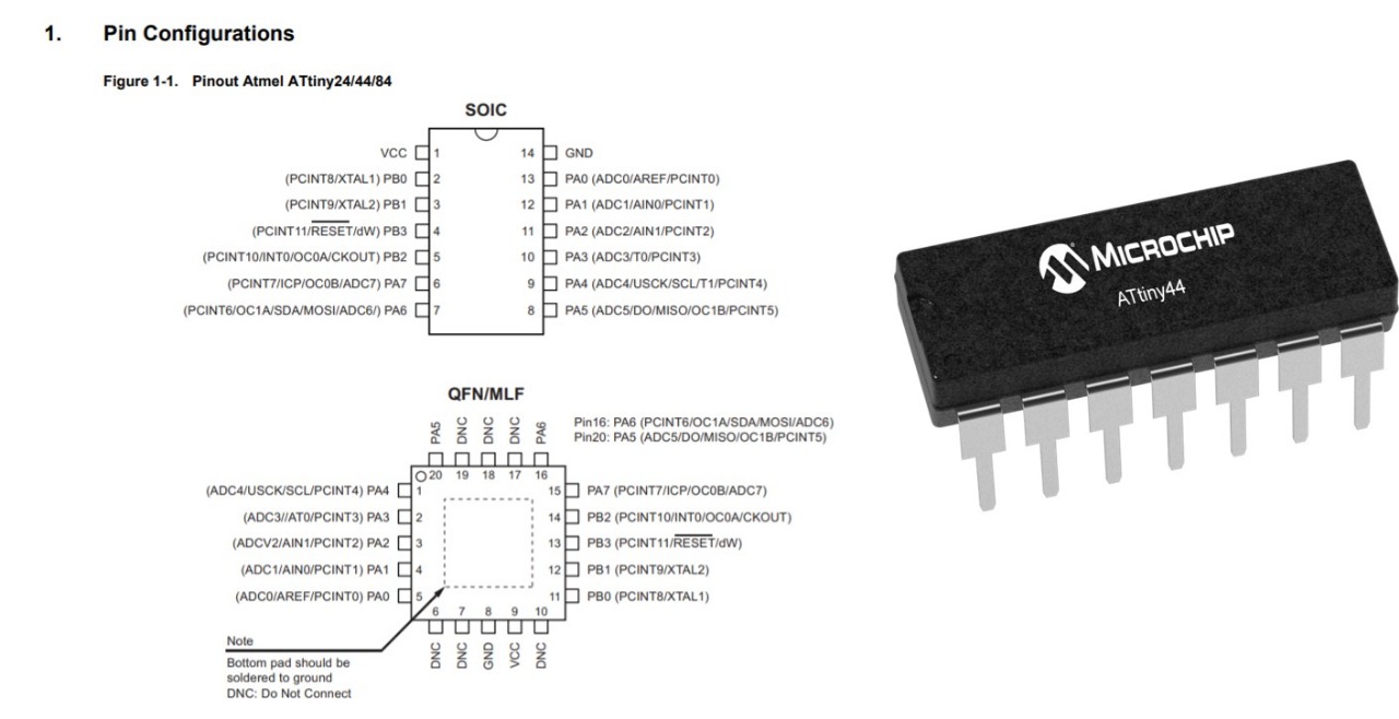
In this circiut I tryed before to program attiny digitaly by using Tinkercad on Embedded Programming week. and as a guied I followed the step on this link.
Code
In this code, I added Adafruit_NeoPixel.h library for controlling single-wire-based LED pixels. each water level has a different analog pin, each level has a different color. I was thinking of using jumper wires with different levels, or copper tape, but I took the advice to make a piece of PCB board with etching different levels, and it works.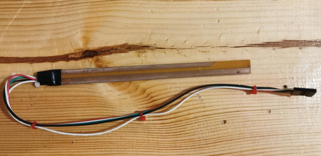
The sensor after atching and soldering the pcb boread.
Tesing the circuit.
Code Files:
Mercury Switch Tilt
A mercury switch is an electrical switch that opens and closes a circuit when a small amount of the liquid metal mercury connects metal electrodes to close the circuit. It is in one state (open or closed) when tilted one direction with respect to horizontal, and the other state when tilted the other direction. This is what older style thermostats used to turn a heater or air conditioner on or off.
Testing the Mercury Switch Tilt Sensor
In this project I will show you how I programmed the mercury switch tilt sensor to act like alarm by using Arduion, for coding I will use Arduino IDE Programming environment, to program the sensor when the sensor switch is closed the LED lights up and the buzzer switche on. When the sensor switch is open the LED and the buzzer switche off.
Components needed:
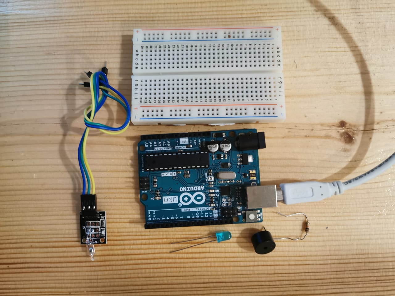
Connctions of the components:
Connction of th Mercury Switch Tilt Sensor:
Connction of the LED:
Connction of the Buzzer:
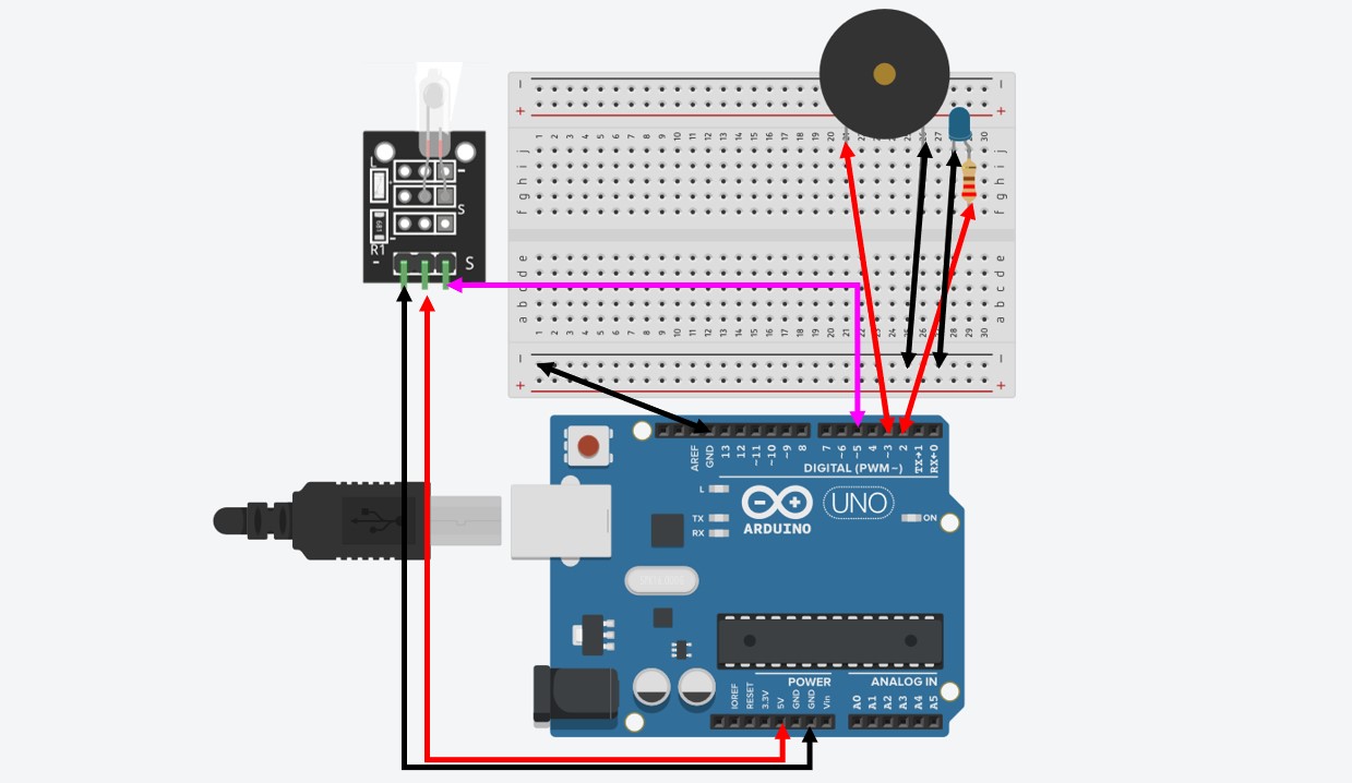
The simulation drowing of the circuit.
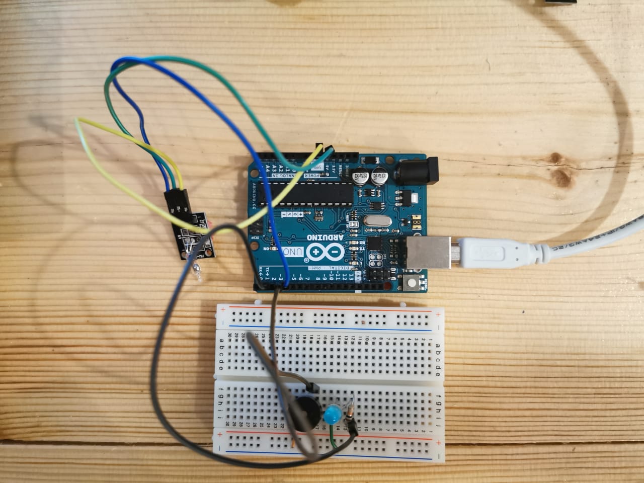
After conncted all the components.
Code
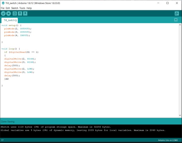
I uploaded the code after verified and checked the errors.
Code Explanation:
    void setup() {
      pinMode(2, OUTPUT);
      pinMode(3, OUTPUT);
      pinMode(4, INPUT);
    }
First, define for the Arduino the variables the digital pins, pin 4 from the sensor is a switch, pin 3 for the buzzer , pin 4 for the LED. Both pins 3-4 the LED and the buzzer are the outputs, they take the sginals from pin 4 the signal sensor pin.
}

void loop() {
  if (digitalRead(4) == 1)
  {
  digitalWrite(2, HIGH);
  digitalWrite(3, HIGH);
  delay(300);
  digitalWrite(2, LOW);
  digitalWrite(3, LOW);
  delay(300);
  }

}
Code File:
LCD medule
Is an electronic display module which uses liquid crystal to produce a visible image. The 16x2 LCD display is a very basic module commonly used in DIYS and circuits.
Testing the LCD module with the Arduino
In this project I will test to program the LCD, to show a short sentince.
Testing the LCD medule
In this project I will show you how I programmed the LCD medule to show us a simple sintance, with controlling the LCD brigthness by using potentiometer. For coding I will use Arduino IDE Programming environment,
Components needed:
Connctions of the components:
Connctions of the LCD:
Connctions of the Potentiometer:
Connctions of the 220ohm:
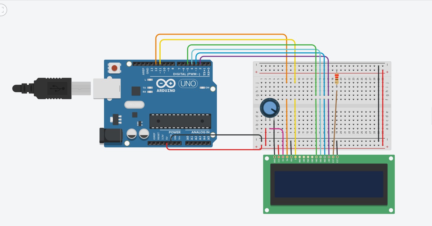
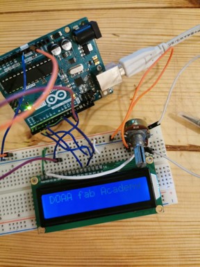
The simulation drowing of the circuit.
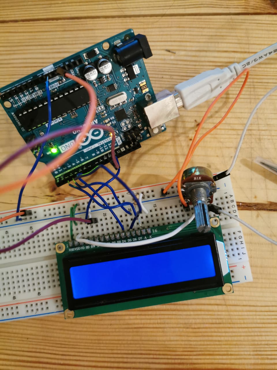
After conncted all the components.
Code
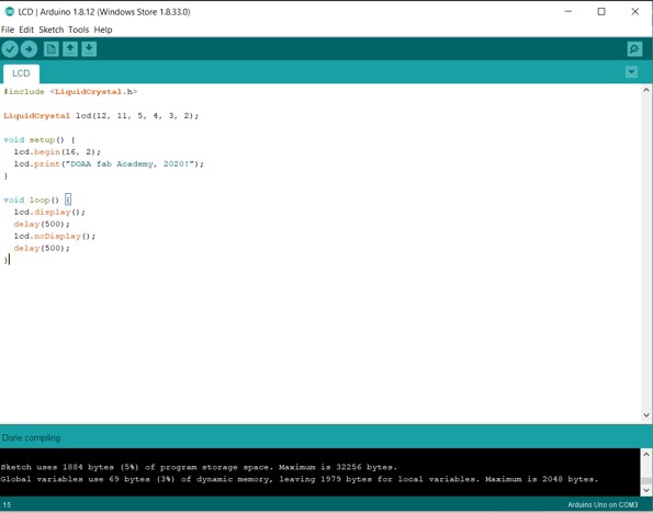
I uploaded the code after verified and checked the errors.
Code Explanation:
    #include

    LiquidCrystal lcd(12, 11, 5, 4, 3, 2);
void setup() {
  lcd.begin(16, 2);
  lcd.print("DOAA fab Academy, 2020!");
}
void loop() {
  lcd.display();
  delay(500);
  lcd.noDisplay();
  delay(500);
}
In the setup() the LCD is initiated with the function begin(cols,rows). In the loop() the cursor is set to the third column and first row of the LCD with lcd.setCursor(2,0). Next, the string ‘DOAA fab Academy, 2020!’ is printed with LCD. Print("DOAA fab Academy, 2020!").
Code File:
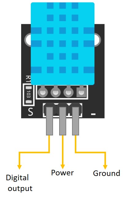
Temp and Humidity Sensor
The DHT11 is a basic, ultra low-cost digital temperature and humidity sensor. It uses a capacitive humidity sensor and a thermistor to measure the surrounding air, and spits out a digital signal on the data pin (no analog input pins needed). Its fairly simple to use, but requires careful timing to grab data. A module with a temperature/humidity sensor type DHT11, Temperature range : 0 - 50°C (+/-2°C), Rel. Humidity: 20-95% (+/-5%), Supply voltage: 3 to 5.5V. With a built-in 10 K ohm pullup resistor. Library: DHT,h.
Testing the DHT11 Sensor
In this project I used the LCD and the DHT11 medule to measure the room temperature and the humidity persntage in the room.
Components needed:
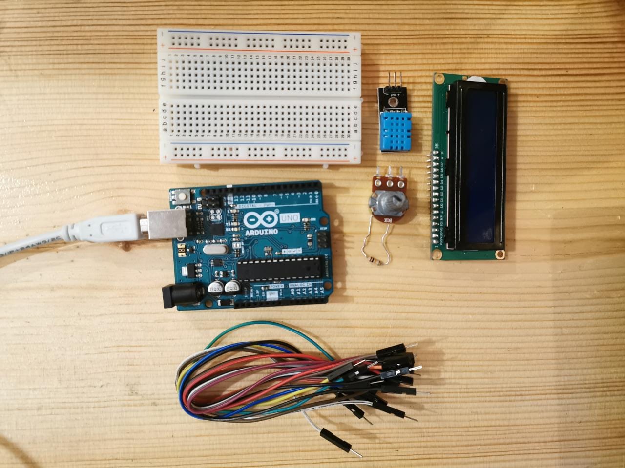
Connctions of the components:
Connctions of the LCD:
Connctions of the Potentiometer:
Connctions of DHT11:
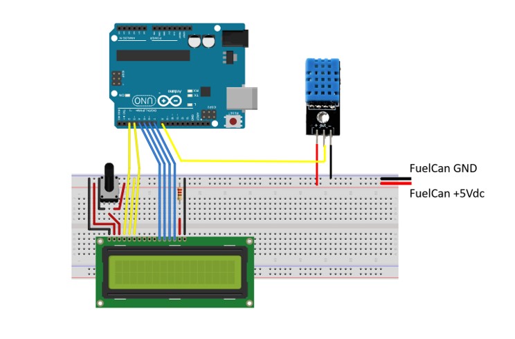
The simulation drowing of the circuit.
Coding
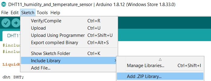
First you need to install the DHTLib library. It has all the functions needed to get the humidity and temperature readings from the sensor. DHTLib
Code
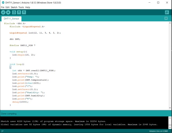
I uploaded the code after verified and checked the errors.
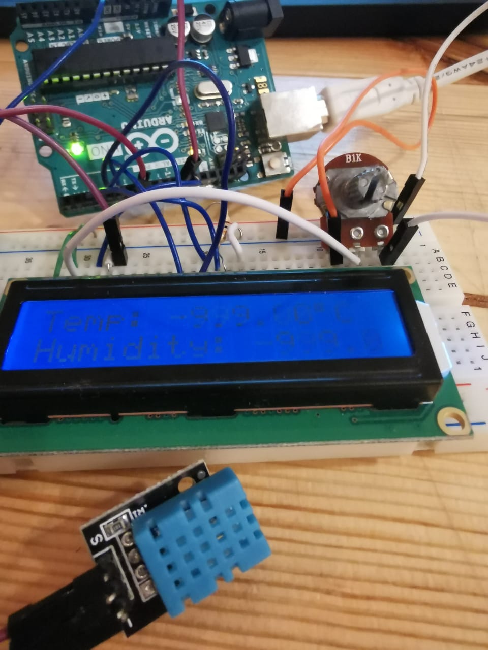
After conncted all the components.
Code Explanation:
    #include
    #include

    LiquidCrystal lcd(12, 11, 5, 4, 3, 2);

    dht DHT;

    #define DHT11_PIN 7
void setup(){
  lcd.begin(16, 2);
}
void loop()
{
  int chk = DHT.read11(DHT11_PIN);
  lcd.setCursor(0,0);
  lcd.print("Temp: ");
  lcd.print(DHT.temperature);
  lcd.print((char)223);
  lcd.print("C");
  lcd.setCursor(0,1);
  lcd.print("Humidity: ");
  lcd.print(DHT.humidity);
  lcd.print("%");
  delay(1000);
}
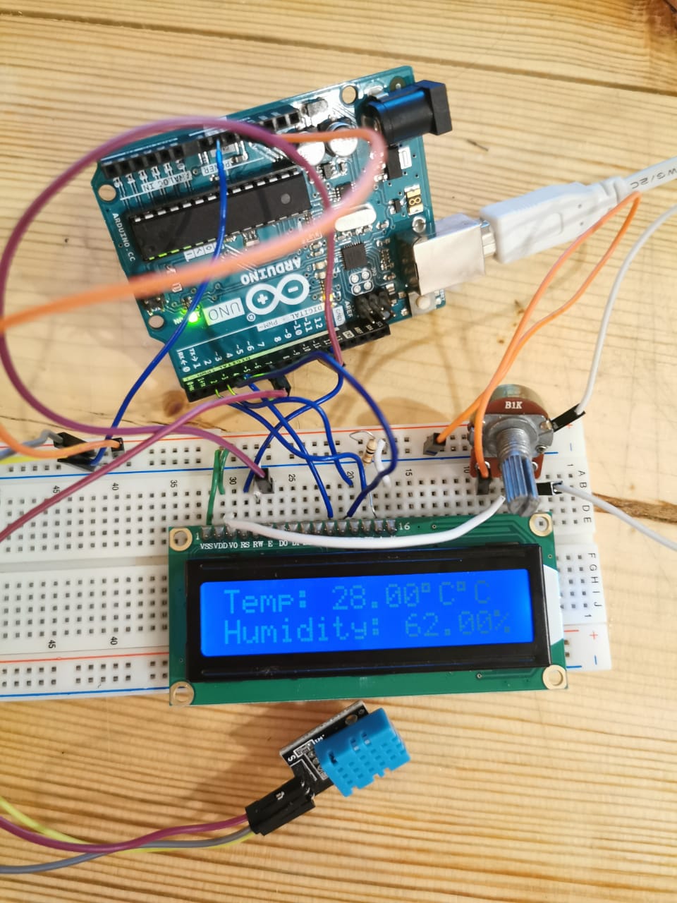
After conncted all the components, and upload the code.
Code File
Add an output device to a microcontroller board you've designed and program it to do something.
Hydration bottel main circuit
In this project I designed the board by using eagle by adding the below compounentes and fabricated as documented on electronics design week: