18. Mechanical design & Machine Design
- Group assignment:
- design a machine that includes mechanism+actuation+automation
- build the mechanical parts and operate it manually
- document the group project and your individual contribution
Project name: Egg Painter for Stroboscopic Animation
Our inspiration comes from the video. With a strobe device the pattern drawn on the egg seems to be “alive”. I will try to input the device as one part of our machine.


Acturally it is a simple eggbot which is very common. But we want to do more so that the machine can draw pattern on many different shape like normal plotter.
For the eggbot is a very classic project, so we can find a lot of refference. Here is some refference of eggbot:
Eggbot by 3Dprinter:

Eggbot by lasercutter:

Eggbot by Lego:

But we deside to make ourown project from the designing to final presentation.
Group menbers and assignment
- I work on the mechanical part.
- Elfe works on the progrem part.
- Shreyas works on the electronic part.
Project development
Concept and Sketch

The electronic components:
It has a wifi moduler, receives commands from the android app, and control the step motors and servos to move
Commands need to handle:
* pen down/ pen up: control the servo spin, to move the pen touch/untouch the egg
* step motor 1, speed x, angle y
* step motor 2, speed x, angle y
* Step motor 3 is not controlled by app commands. It is controlled by electronic components directly, to move the egg between painting or staging area.
The android app:
Allows user to draw a pattern and then convert it to machine commands, and send it to the machine.

Computer aided design
For I work on the mechanical part. So I used Fusion360 to do the design job. But at the first time there is a little problem using Fusion360, for I desided to use the Aluminum profile to make the XY axis which will make the assemble much more simple. In fusion even I can insert the components directly from McMaster, but all the dimension is Inch size, all I need is in Metric size. So I turn to another powerful plugin in Solidworks which called MISUMI rapid design. From Which all the components that I want is in Metric size.
For example if I want to use a Linear Guides. I can choose the type from the menu in the interface. Then modify the dimesion that I want. Solidworks will creat the component automaticly.

Then I can save it as STL file and use other software to keep designing(Solidwords is good, but my computer can’t run it smoothly for low configuration so I desided to use Fusion 360).
The XY movement part:

Pen control part:
Use the 9g servo to control the pen up/down. And there is a little spring between two part to let the pen has more freedom not to crush the egg for too much fore on its surface.

This is the first version:

This is the final version of our mechine:

3D model
(Some litte components has not been added yet because it is easy to assemble but takes long time to model it. I will try to update it later.)
Fabrication and Assemble
To fix the stepmotor with the frame, I used lasercutter to make some components then use the special nut which called T-nuts to fix them together.


Tighten the time belt with the zip tie or called Cable tie.

Then I used 3Dprinter to print some little components for example the pen fixer.

Here is the frame looks like:

The electronic part
Most of this part is documented by Shreyas-tiwari. More detial from here.
The electronic part’s function is to controll the step motors for the machine. The controller which called CNC shield is designed to allow you to control a CNC router/milling machine from an Arduino board. It contains 4 driver sockets which allows compatible Pololu A4988/DRV8825 driver modules to be inserted providing the ability to drive 4 stepper motor axis.
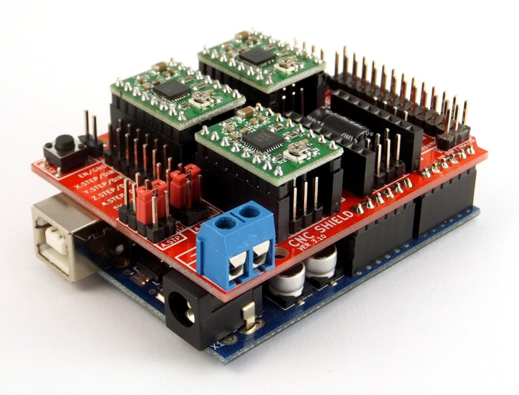
There are lot of refference tutorials from Youtube and other platform.
Our control system equals to a 4 axis CNC system add one servo. The main function of drawing pattern on the object will just use 2 step motors. One controls the object’s rotation. One controls the pen’s position. And the servo controls the pen’s Up/Down. The other two step motor is for auxiliary. If the object is very big. Such as a melon or a bottle just like this:
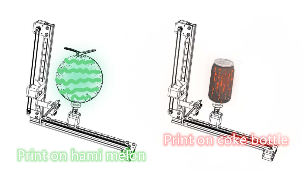
The X/Y movement control step motors can adjust the position of the object and the pen to fit them for painting. As the same time we can simply change the clamping device to fix the object.
Testing
To the preliminary commissioning stage, we used the CNC shield to drive two step motors. Everything looks good.
Then we added the servo and test again.
So~ till now, the electronic part is ok. We can keep going on the next step.
The programming part
Most of this part is documented by yanfei-xu. More detial from here.
The programming part’s function is to creat the G-code for the electronic part from a patter drawn on an app or an interface.

At the first time we tried App inventor to make an app for user to upload the patterns they will draw, and creating the G-code for the electronic part.
But we found some problems: The App inventor runs too slow, so we cannot get nice animations. And the stroboscopic animation requires specific patterns that can match with the flash nicely. However, draw by finger on the phone screen cannot be so precisely, and the animation will be messy.
So We decided to use Processing as the interface. Using the knowledge learned from week13. The most difficult part is to use processing to create G-code which requires a lot of math process to change the pattern into position.
The code can be download from Files.
How to use?
After uploading the pattern to Processing, it will creating the G-code for Arduino automatically and drive the step motors and servo.
Testing
We found it hard to print on the surface of the egg, so we choose a ball instead. And we used the hotglue to fix the object without the fix device.
Something worth improving
- The coupling should be rigid rather than flexible.
- The clamping device should be designed to be stronger to hold the object tight.
- Between the object and the clamping device should be some material like felt because the surface of the object is very smooth. With the rotation of step motor the object will slip which will lead to the pattern mess even the programming is right.
- The cables for step motors and servo should be well organized.
- Making a upper computer with simple VI for the users.
- Choose a proper oil-ink pen instead of the watercolor pen.
Files
Printer_structure(Fusion360_web_preview)
eggpbot.stp
eggbot_arduino.ino
eggbot_processing.pde