9. Embedded programming
Assignment
- individual assignment:
- read a microcontroller data sheet
- program your board to do something, with as many different programming languages and programming environments as possible
- group assignment:
- compare the performance and development workflows for other architectures
Read a microcontroller data sheet
Pin configurations

| ISP Pin used on my board | FTDI Pin used on my board |
|---|---|
 |
 |
The pins I have used for my board:

Clock system
From page 24 talking about the clock system:
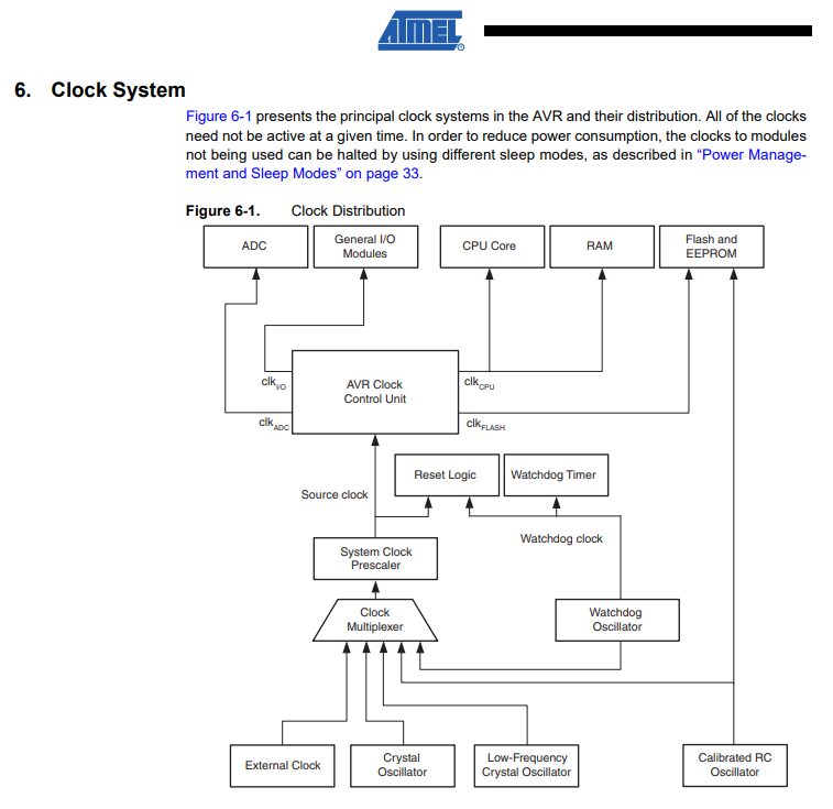 There are many clock source options and the selected source is input to the clock generator. The clock source are used to many modules such as timer, cpu, flash, ADC and I/o.
System Clock Prescaler The ATtiny24A/44A/84A system clock can be divided by setting the “CLKPR – Clock Prescale Register” on page 31. This feature can be used to decrease power consumption when the requirement for processing power is low. This can be used with all clock source options, and it will affect the clock frequency of the CPU and all synchronous peripherals. clkI/O, clkADC, clkCPU, and clkFLASH are divided by a factor as shown in Table 6-11 on page 32.
Reading this part helped me to solve the problem of blink program test.
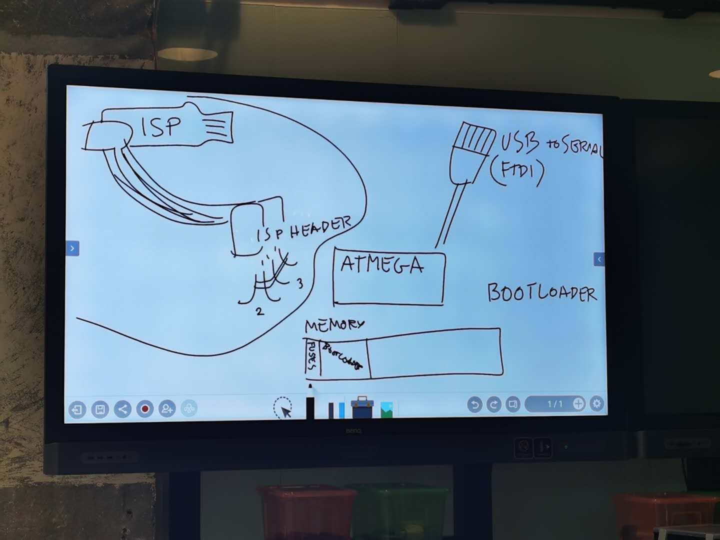
Bootloader
- A piece of code that runs before any operating system is running…used to boot other operating systems.
- First software to run after startup
- Highly processor and board specific
Program my board to do something
Connection for my board
An ISP cable was used to connect my board to an existing programmer like FabISP or Arduino. I used a working FabISP as the programmer to program my new made PCB.

I downloaded the echo.c and echo.c.make file from Neil’s page. Which is named as hello.ftdi.44.echo.c and hello.ftdi.44.echo.c.make.

Make fuses
What is fuses? There are 3 bytes of permanent storage in the chip called ‘fuse low byte’, ‘fuse high byte’ and ‘fuse extended byte’. These bytes are called fuses and can be reprogrammed as many times as you want and determines the behaviour of the chip. To do that, their value is not erased when the chip is powered off or reprogrammed.
Each microchip has its own definition for the values that must have the fuses. In this assignment, we are going to work with the fuses of the Attiny44A. I opened the terminal Git bash, then enter the following commands:
cd (file address)
make (two files will be created in the folder)
make program-usbtiny
make program-usbtiny-fuses
cd & make:

two new files in the dictionary:

make program-usbtiny & make program-usbtiny-fuses:


Tip
before use make , the file name hello.ftdi.44.echo.c.make should be renamed as Makefile

Use Arduino for programming
Arduino IDE setting:
Followed the tutorial
Installing ATtiny support in Arduino using the built-in boards manager.
- Open the preferences dialog in the Arduino software.
- Find the “Additional Boards Manager URLs” field near the bottom of the dialog.
- Paste the following URL into the field (use a comma to separate it from any URLs which has already been added):

- Scroll to the bottom of the list; you should see an entry for “ATtiny”.
- Click on the ATtiny entry. An install button should appear. Click the install button.


- Make sure these settings are same as the make file decribed:

The description in make file:

Tip
Use USE PROGRAMMER TO UPLOAD not directly use UPLOAD

Programming 1:
Blink test
Codes:
int ledPin = 7;      /refer to ATtiny44 datasheet

void setup() {
  pinMode(ledPin, OUTPUT);
}

void loop() {
  digitalWrite(ledPin, HIGH);   /turn the LED on
  delay(1000);                       /wait for a second
  digitalWrite(ledPin, LOW);    /turn the LED off
  delay(1000);                       /wait for a second
}
Outcome:
I found a problem: the delay time in my program is 1 second, but it seemed to be about 8 seconds. This is probably because we are using the fuse file written in C by Niel, which may not contain the “divide by 8” fuse setting which is more commonly set for microcontrollers. Arduino expects the “divide by 8” setting on microcontroller and tries to make up for that. In our case, it slows down because our board works in normal speed. After burning the bootloader, the microcontroller’s setting matchs with Arduino’s, and the 8x slower issue gets solved.


Programming 2:
Use button to control LED
Codes:
int buttonPin = 3;      /refer to ATtiny44 datasheet
int ledPin =7;      /refer to ATtiny44 datasheet
int buttonState = 0;

void setup() {
  pinMode(ledPin, OUTPUT);
  pinMode(buttonPin, INPUT);
}

void loop() {
  buttonState = digitalRead(buttonPin);

  if(buttonState == HIGH){
    digitalWrite(ledPin,HIGH);
  }
  else{
    digitalWrite(ledPin,LOW);
  }
}
Outcome:
Programming 3:
Serial control LED
Tip
ATtiny44A has no Serial function, must use SoftwareSerial instead.
Codes:
#include <SoftwareSerial.h>

SoftwareSerial mySerial(0, 1); // RX, TX

const int LED = 7;
char incomingByte = 0;
void setup() {
  mySerial.begin(9600);
  pinMode(LED,OUTPUT);
  digitalWrite(LED,LOW);
}

void loop() {
  if(mySerial.available()>0)
  {
    incomingByte = mySerial.read();
    mySerial.println(incomingByte);
    if(incomingByte == '1')
    {
      digitalWrite(LED,HIGH);
    }
    if(incomingByte == '0')
    {
      digitalWrite(LED,LOW);
    }
  }

}
Outcome:
Programming 4:
ISP pin control RGB LED
Codes:
int redPin = 4;
int greenPin = 5;
int bluePin = 6;
void setup(){
 pinMode(redPin, OUTPUT);
 pinMode(greenPin, OUTPUT);
 pinMode(bluePin, OUTPUT);
}
void loop(){
 //R:0-255 G:0-255 B:0-255
 colorRGB(random(0,255),random(0,255),random(0,255));
 delay(1000);
}
void colorRGB(int red, int green, int blue){
 analogWrite(redPin,constrain(red,0,255));
 analogWrite(greenPin,constrain(green,0,255));
 analogWrite(bluePin,constrain(blue,0,255));
}
Outcome:
Also I could see the color change, but I found a problem: Because I use RANDOM function to change the value for controlling the RGB, but seems there is few blue appears. I thought it is the PIN problem so I check the datasheet(Reference) and the PIN names:

In Arduino, Pin 4 has no PMW function, so in my ISP PIN there is only two PIN can change value from 0-255 linearly.
Reference

Original files:
Blink.ino
Buttom control LED.ino
Serial control LED.ino
RGB LED