Machine and Mechanical Design
Tasks for this week:
- Design a machine that includes mechanism + actuation + automation.
Part 1- Test Cartesian Plotter
To get some experience with working with different types of components and electronics we can use this week, we initially made a X-Y axis plotter. To be more time efficient, we used aluminium rails for the overall structure instead of plywood. The end result of this group exercise is at the end of the page.
Since we are 6 people in our lab this year, we will be making 2 teams working on 2 projects. I am working with Elfe and Pan Cheng to make a ball-drawing robot, which will use stepper motors to move and rotate the ball as the pattern is being drawn, as well as a servo motor for pen-up movement. For this week, I will be documenting the use of the CNC shield for Arduino, since stepper motors will be used extensively in our project. as it is one of the most common output device utilized in many applications.
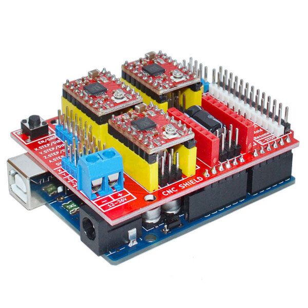
This CNC shield is designed to allow you to control a CNC router/milling machine from an Arduino board. It contains 4 driver sockets which allows compatible Pololu A4988/DRV8825 driver modules to be inserted providing the ability to drive 3 stepper motor axis (X,Y, & Z).
The first thing to do before connecting the CNC shield to the Arduino is to upload the GRBL library.
- Download the GRBL source code. Download here
- Unzip the download and you’ll have a folder called "grbl-master"
- Launch the Arduino IDE. (Make sure you are using the most recent version of the Arduino IDE.)
- Load GRBL into the Arduino IDE as a Library. (Click the "Sketch" drop-down menu, then navigate to "Include Library", and select "Add .ZIP Library")
- IMPORTANT: Select the "Grbl" folder inside the "grbl-master" folder, which only contains the source files and an example directory.
- Open the "GrblUpload" Arduino example. (Click the "file" down-down menu, navigate to "Examples->Grbl", and select "GrblUpload")
- Compile and upload GRBL to your Arduino. No modifications are required.
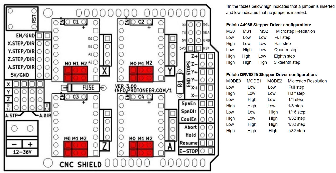
To work with the CNC shield, the first thing to do is place the A4998 drivers on the shield. The shield can work with X, Y and Z axis, with a 4th position available to add another motion in one of these axis. Since our plotter is a 2-axis machine, we only needed to place the driver in the top left and top right slots, matching up the Enable pins on both. NOTES: 1. You must add a heat sink to the driver for the stepper motors to work effectively. 2. The capacitor required for the driver to work is already in the shield and is located just under the driver.
Within each driver location are pins for microstepping, which achieve greater precision in exchange for torque.
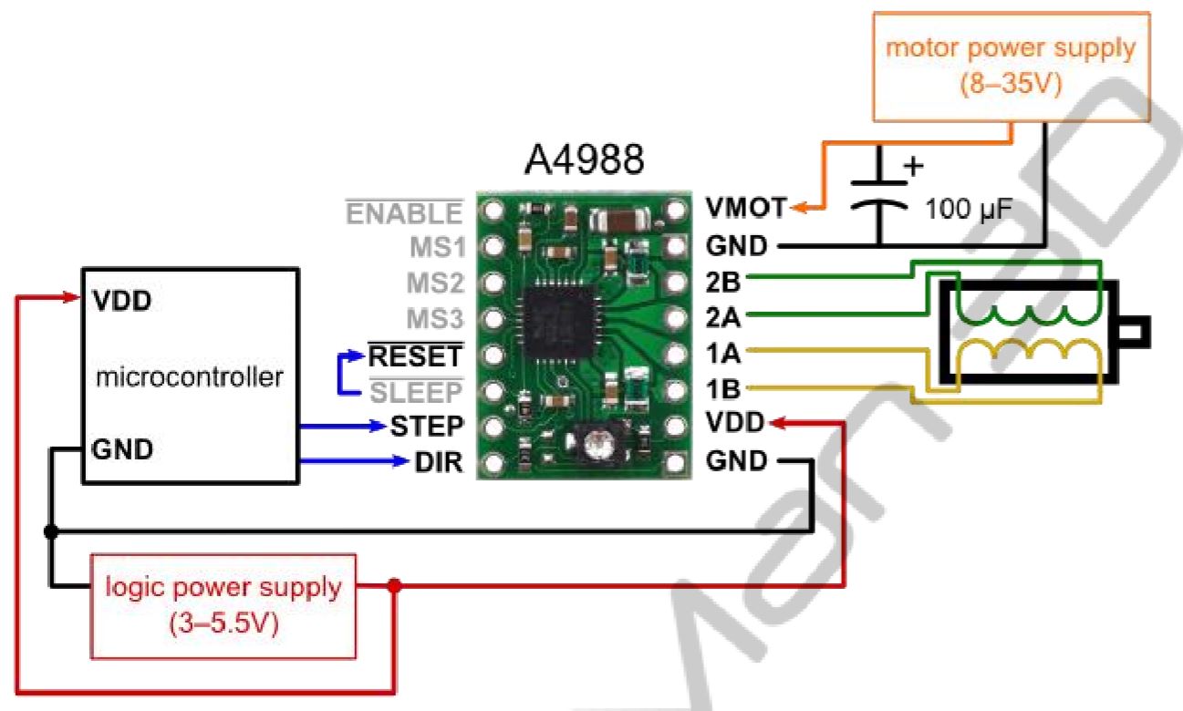
Connecting the stepper motors is a very simple job. The four stepper motor pins for the coils will connect to the shield, although the direction cannot be confirmed so there may be some trial and error involved. NOTE: Before changing the connections to the driver, make sure that the power supply is disconnected, otherwise the stepper motor or the driver could get damaged.
After running the code in Arduino, now install the Universal GCODE sender (UGS Platform) software, a Java application, which will let you control the motors and input a GCODE. The user interface is quite simple, however the parameters for the different functions (see below) need to be modified to suit the project's requirements.
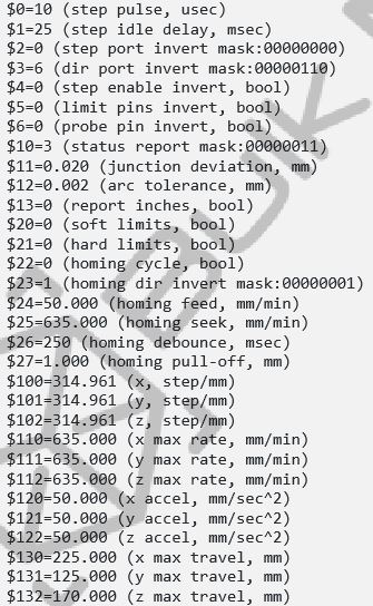
Working with the Universal Gcode Sender was easy, since we had defined how many number of motor steps is required for 1cm of movement. We could control the plotter in the X and Y, + and - negative directions. We quickly taped on a pen to draw on the paper, and the concept worked (to some extent). However, for the automation in this project, we needed to upload a Gcode. You can use InkScape with an extension, but we preferred to use an online one (Eazel by Inventables). Once the gcode was generated, we uploaded and sent it to the machine. In the live preview, we could see that the motion that was supposed to happen was working, however, the range of our plotter was much smaller, and it also didn't have a pen-up, so any movement across the plane was also drawn. Nevertheless, we had managed to get the basic concepts working.
Egg Bot
I participated in this project alongside Pancheng and Elfe. For this project, we divided our tasks into 3 main sections: structure design, electronics, and application interface.
Documentation by Pancheng on the structure:
Link
Documentation by Elfe on the Interface:
Link
Individual Contribution:
I was working on the electronics part of the project, which was quite simple, since it involved several stepper motors controlled by a shield (documented above), as well as a servo motor for the pen-up function. I worked alongside PanCheng and his CAD models to understand how the motors would be mounted onto the structure.

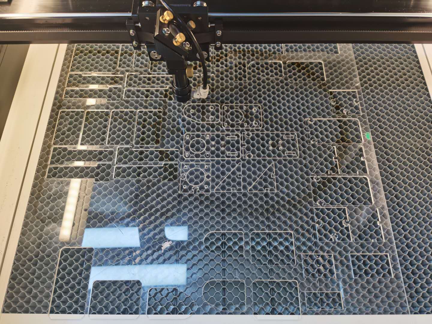
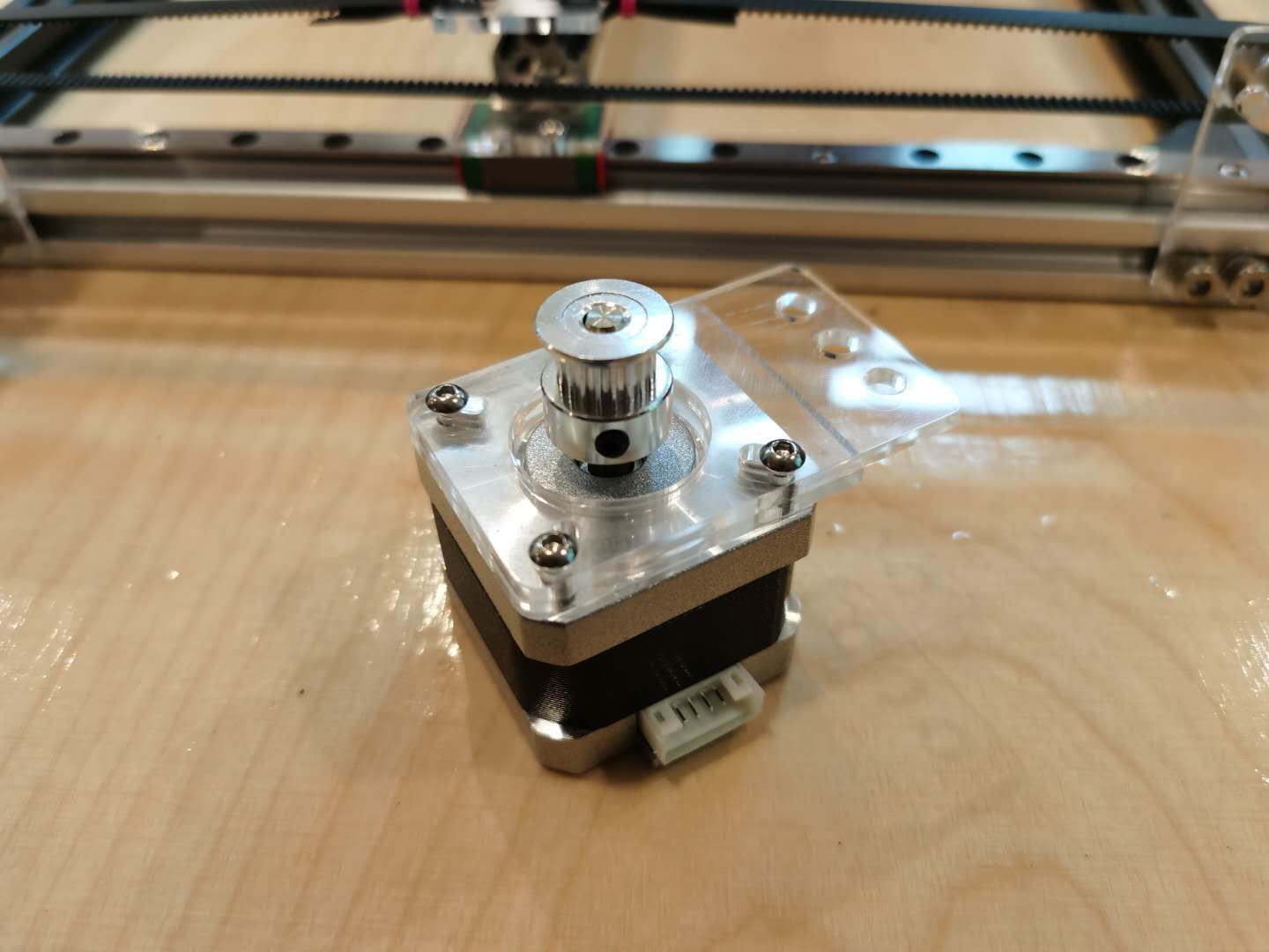
For mounting the stepper motors and for the pen-support with the servo motor, we laser cut components to which we can screw in t-nuts to attach onto the aluminium rails.
I then worked with Elfe for the stepper motors. I attached the shield on top the Arduino Uno, inserted the Pololu A4998 drivers, and connected the 2B,2A,1A,1B pins from the shield to the motors respectively. We uploaded the built-in example code for the MultiStepper. The motors were working fine, so the connections were good to go. However, there was an error; the motors would only move one after the other, not simultaneously.
I checked the power supply, all connections for the pins, but to no avail. I then realized that if both motors are moving smoothly, as seen above in the video, then it might be an issue with the code. It turned out it was an issue with the code, and she modified the code to set maxSpeed instead of Acceleration, and the motors worked well finally.
My final task in my role was to figure out how to also make the servo motors work. Since the shield occupied the entire area above the Arduino Uno, there were no free pins to connect to. Even though we have 4 stepper motors in the machine setup, lcukily only two need to run simultaneously. Therefore, I connected the servo with the stepper motor shield's Z step pin, and it worked fine.
There are several more developments we want to continue on this project, but we were restricted by time constraints. A personal spiral development (not for the core function of the system but a personal preference) would be to add a coin/token recognition system, where you insert it in to activate the entire machine. This development would add more engagement with the user in real-world applications.
Here's the video of our final result: