
Week 11. Output Devices
This week there are also two types of assignments, one group and one individual. In my case being alone in the Fab Lab, I do both.
- Measure the power consumption of an output device. ✔
- Document your work (in a group or individually). ✔
- Add an output device to a microcontroller board you've designed and program it to do something. ✔
- Linked to the group assignment page. ✔
- Documented how you determined power consumption of an output device with your group. ✔
- Documented what you learned from interfacing output device(s) to microcontroller and controlling the device(s). ✔
- Described your design and fabrication process or linked to previous examples. ✔
- Explained the programming process/es you used. ✔
- Outlined problems and how you fixed them. ✔
- Included original design files and code. ✔
- Included a ‘hero shot/video’ of your board. ✔
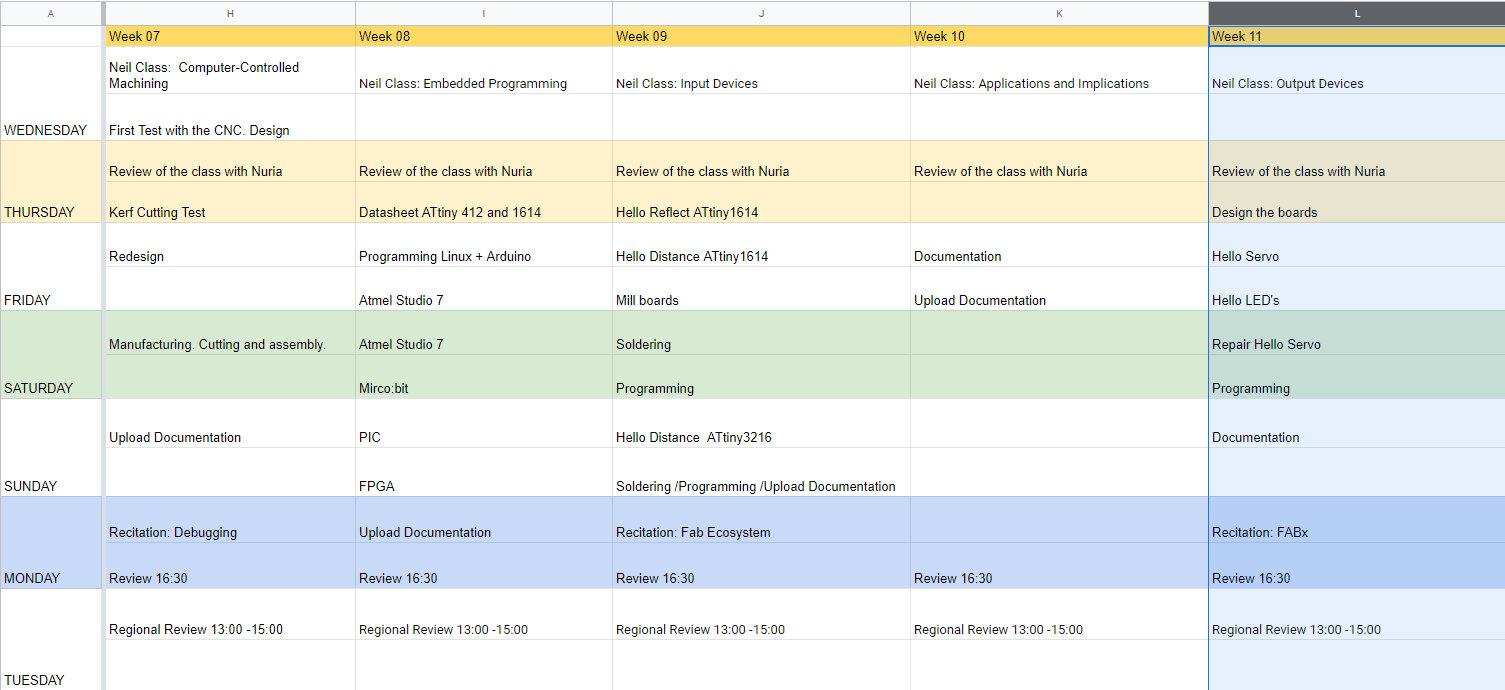
Like every week, my weekly schedule. 😊
I start the Output Devices week after randomly going out on review Wednesday, Neil recommended that I try to network my project. This week I will try to do two outputs, one Hello Servo and another Hello LED. My idea is to try to test the outputs that I am going to use for my final project. Also I am going to add to the I2C the Serial connection (TX, RX). 😅
Group Assignment
The Group Assignment page is at the following link.
If you click on this link, you go to the Group Assignment section that I have done for this week.
Hello Servo
Design
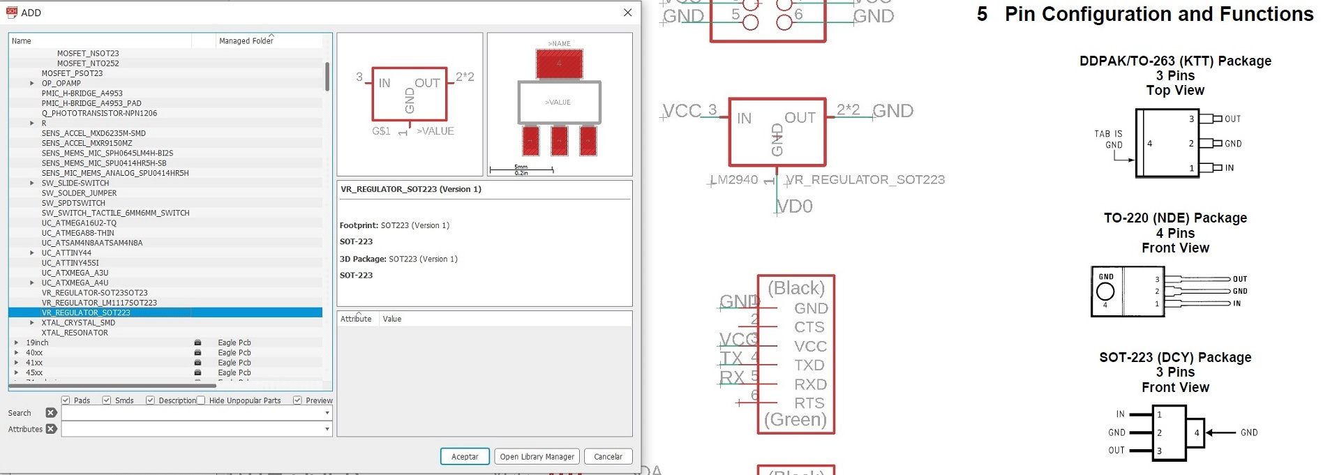
For the Hello Servo I am going to use the ATtiny 1614 with Eagle (in week 09 of Input Devices I download the footprint of the microcontroller). I'm going to use a 9V battery to power the board, so I need to use a voltage regulator. Looking at the inventory of the Fab Lab León there is the LM2940. We must be careful when we place the component in the schematic, because the pinning does not match and we must look at the Datasheet. In this case I use package SOT223.
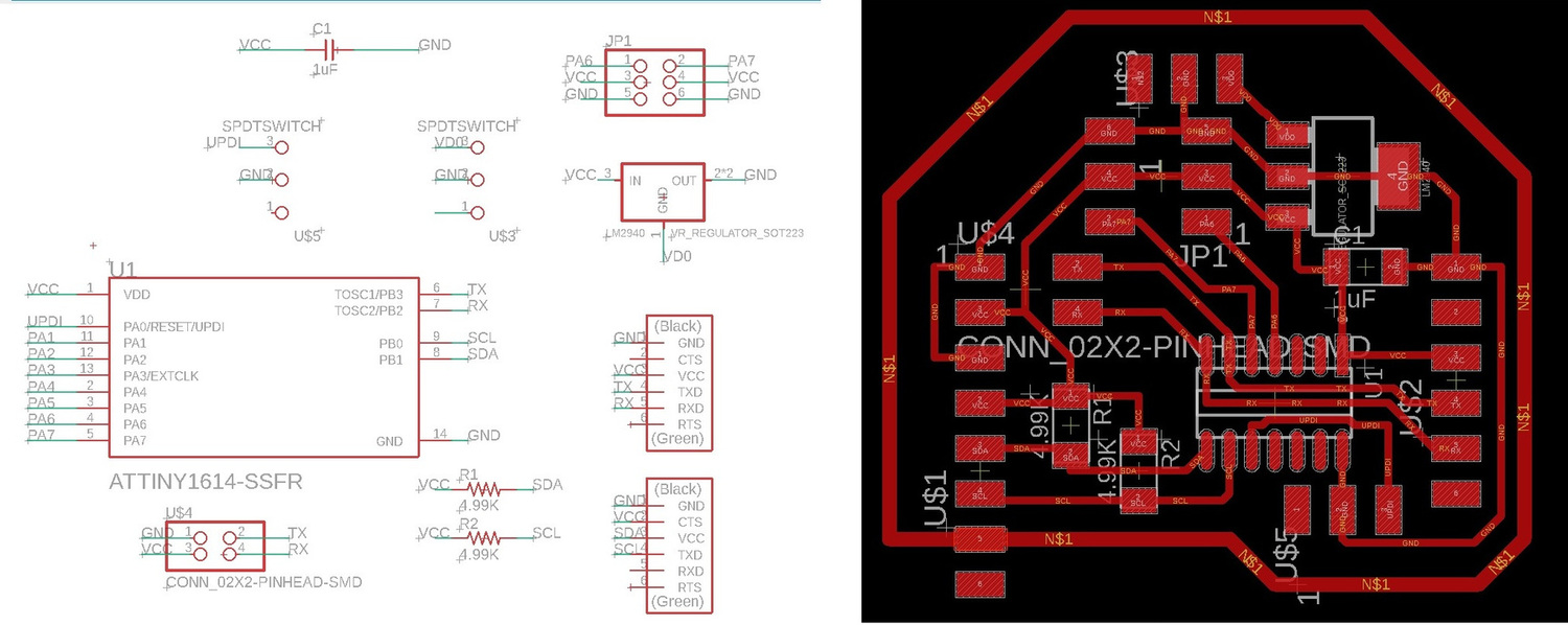
As a recommendation from Nuria and Pablo, it is always good to guide the Inputs or Outputs boards for the Networking week. In the week of Inputs, the Hello Reflect board set the I2C protocol and through the FTDI I could connect it to the Serial Bus (TX and RX). For the Hello Servo I will also incorporate the I2C and the Serial Bus (this time with a separate connector). Here is the schematic and the board.
Making
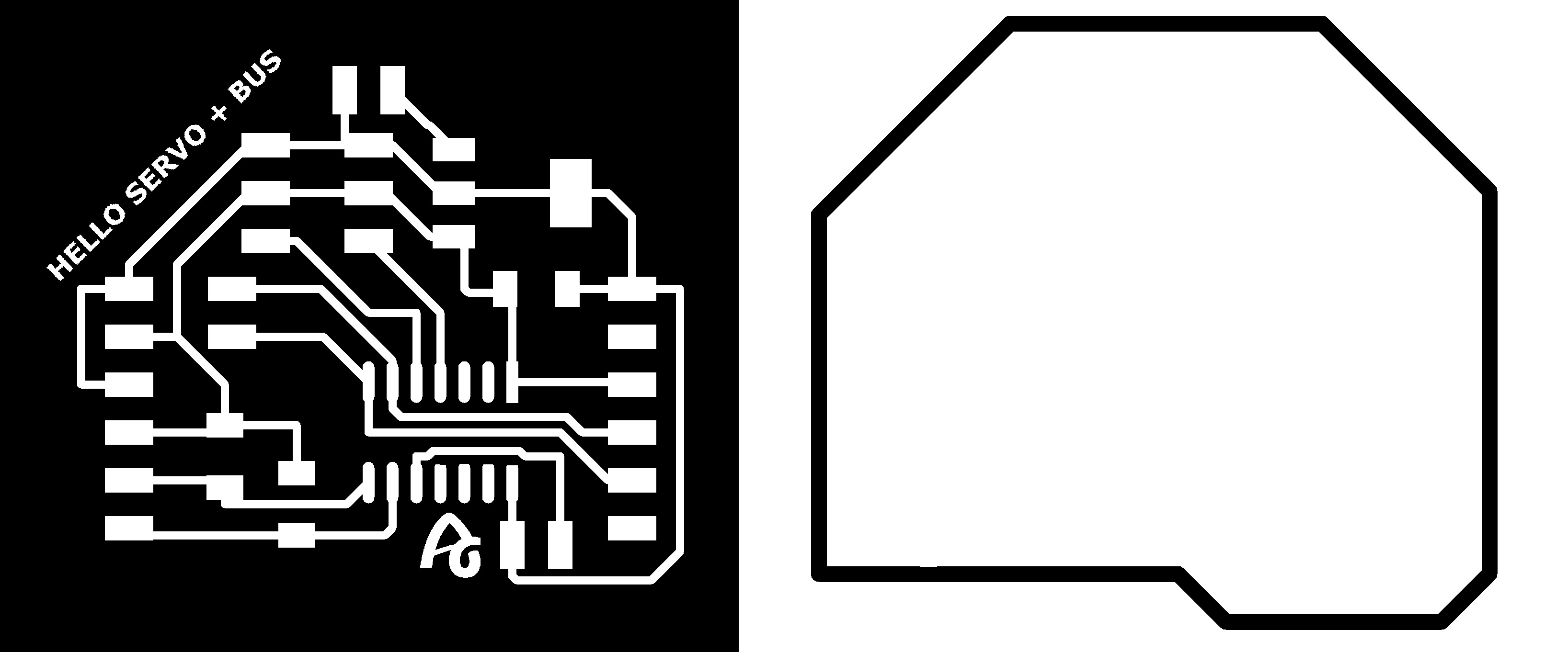
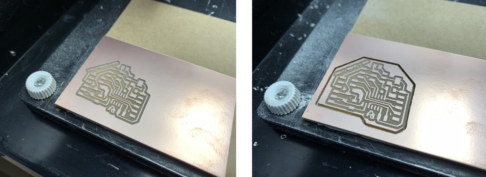
And these are the two images ready to use in the Modela.
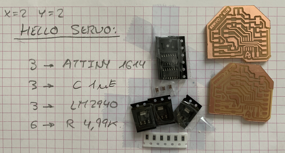
With Mods CE and the Modela, I mill the board. The starting reference points are X = 2 Y = 2; but apparently the machine when it did the milling with the 1/32 milling cutter did not take that origin. 😥
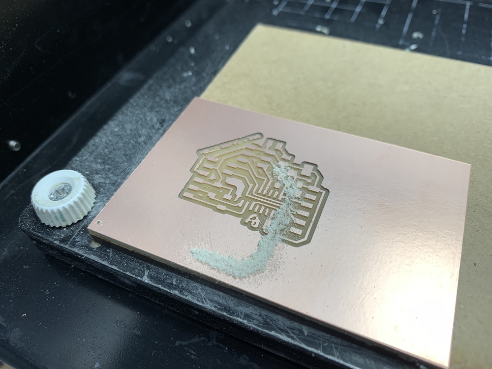
I don't know why strange reason lost the origin of the Modela. As the board does not enter me again, I take advantage of it for the other board. I put another new copper board back and it looks good.
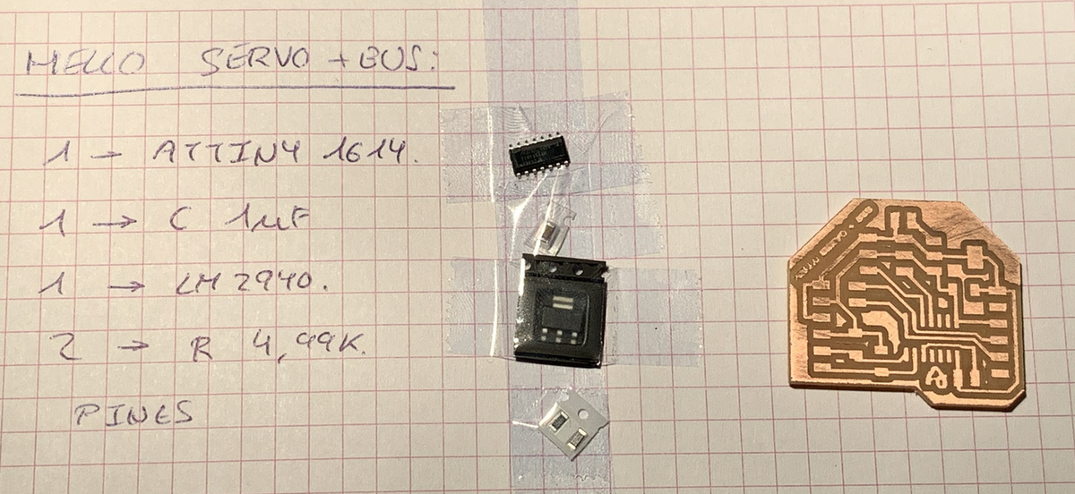
For this board this is the list of components for this board, an ATtiny1614, the LM2940 voltage regulator, the 1uF capacitor, the resistors 4,99K for the I2C and various connection pins.
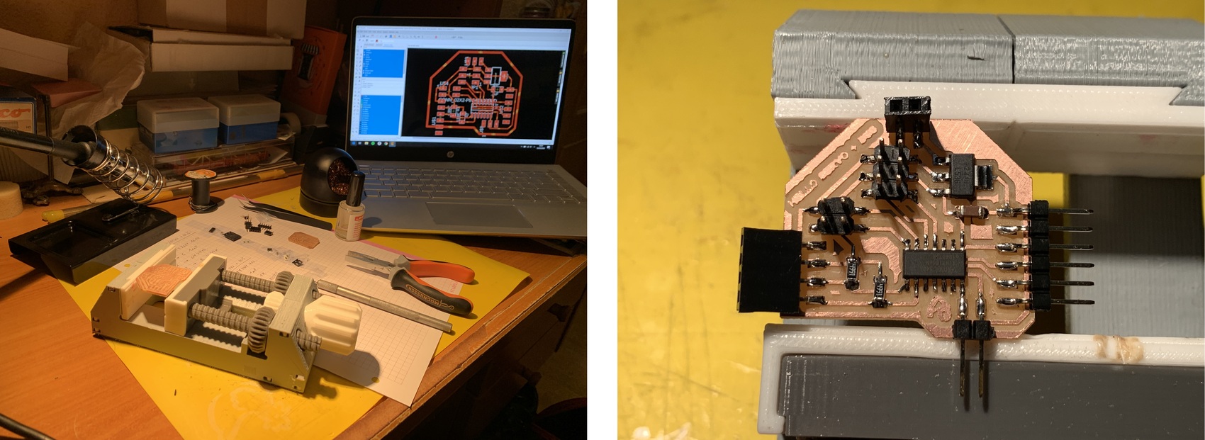
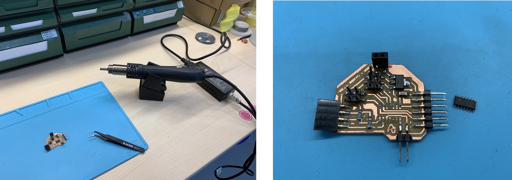
And since we are confined at home 🏠, this is my desk converted into a Lab (any day my mother will kick me out of the house)😅😂. And the result of the board finished soldering.
The time-lapse of the ATtiny1614 soldering process for servos.
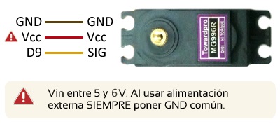
The servo connection is important, for this I follow the connection instructions on the Luis Llamas website.
Programming: Arduino + Linux.
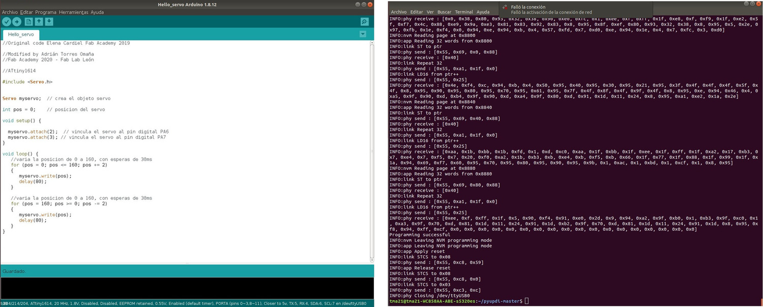
For the programming of the ATtiny1614 I am going to use the program that Elena Cardiel used to move a servo in its week of output. In my case the outputs of the ATiny1614 are PA6 (Pin 2 of Arduino) and PA7 (Pin 3 of Arduino).
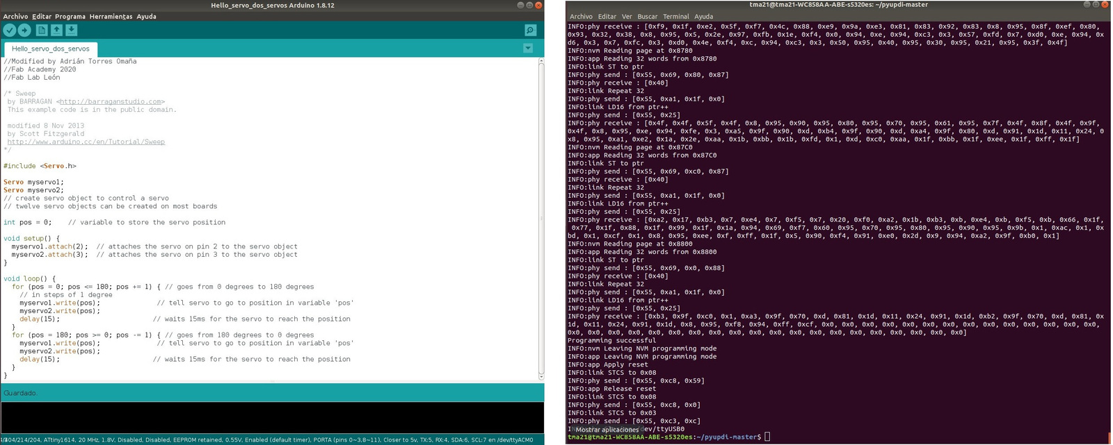
For programming I follow the steps as in week 08. I compile the Arduino program, copy the .hex file and paste it in the Pyupdi folder. Through the Pyserial and UPDI I program the board, and the programming is successful.
After programming is complete, I disconnect the UPDI and connect the servo with the FTDI cable attached. The servo goes very slow and freezes, it no longer moves. 😬 It was so fast that I don't have time to record it. I think it is a power problem, so with the FTDI connected I connect the 9V battery. Nothing remains the same, the servo is blocked. I try to program it again and it gives me the following error. 😫
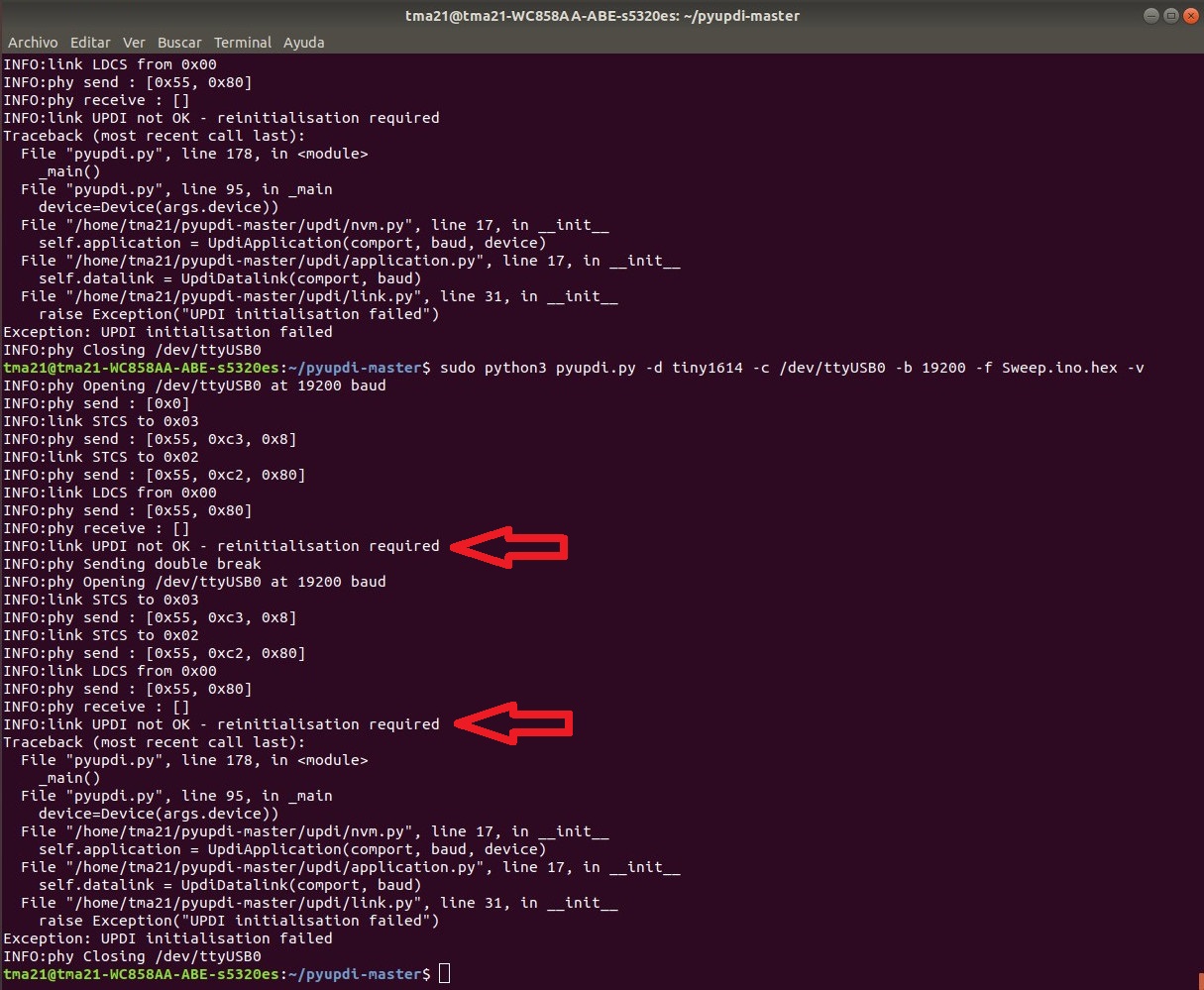
I mention it to my instructor Nuria and she recommends several things. Let it re-soldering the board (done); to measure the battery voltage (8.5V) so that the regulator works (sometimes if it is not more than 5V the regulators do not work); measure with the multimeter whether the regulator does its job (it is correct); measure with the oscilloscope the ATtiny outputs going to the servos (it gives a continuous signal of 0.8V and 5v respectively, and a servo has to be pulses). I have also looked at the following link where the same error occurs "UPDI not OK - reinitialisation required" and they recommend disconnecting the microcontroller for about 20 seconds to reprogram it and nothing. Also in this link they say to use a cable to program with an FTDI 232 and it does not work either. I think my ATtiny1614 is dead. 💀
That same afternoon I wrote an Issue in class to see if anyone had happened to it. Neil wrote to me and said it could be a lack of power for the servo.
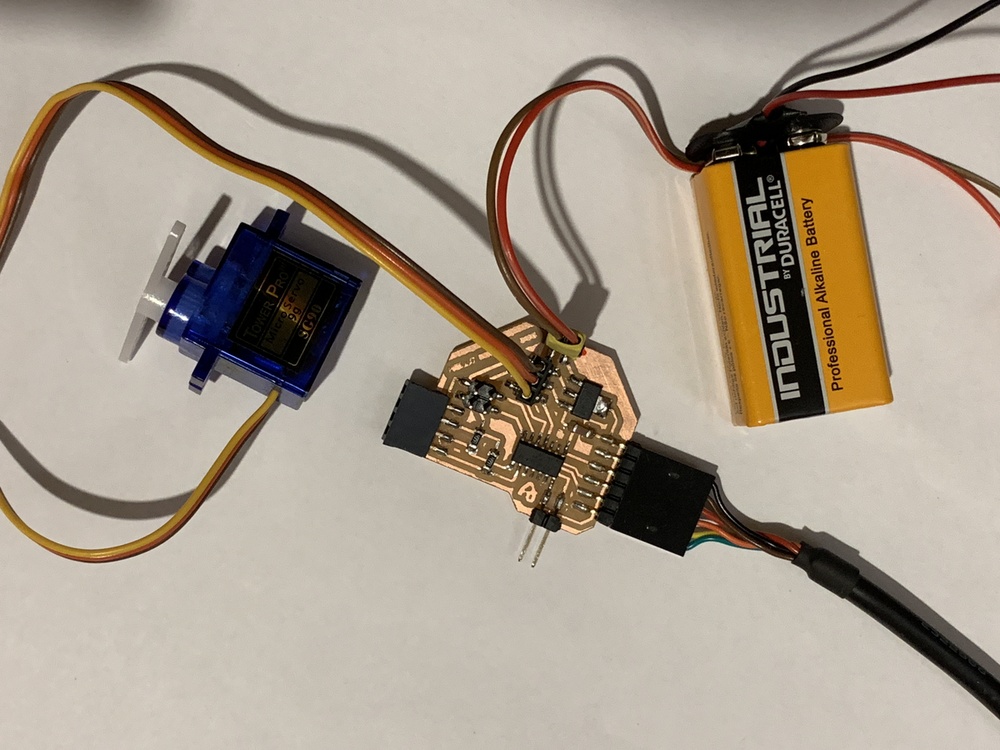
This is the connection and the servo moves a little bit and then stops.
After turning my head at night 😴, I wake up on Saturday thinking that I may have made a mistake in choosing the pins to activate the servos because the PA6 and PA7 have no PWM output. So I redesigned the board again, changing the output pins to PA4 and PA5. Nuria tells me to mill the new design of the board, but to replace the ATtiny1614 that doesn't work with a new one.
Pablo asks me to show him the code, and he tells me that by using the Arduino "Servo" library; it is not necessary to assign specific pins, since software creates a virtual PWM. Here is the link of this information.
These are the two new boards that I have created in case the ATtiny1614 replacement doesn't work for me. It has changed the PA6 and PA7 pins for the PA4 and PA5, which do have PWM.
So the first step is to desolder the ATtiny with the heat gun.
The little ATtiny is already in place, it costs a bit because you have to see that all the pins are seated on the board. 😅
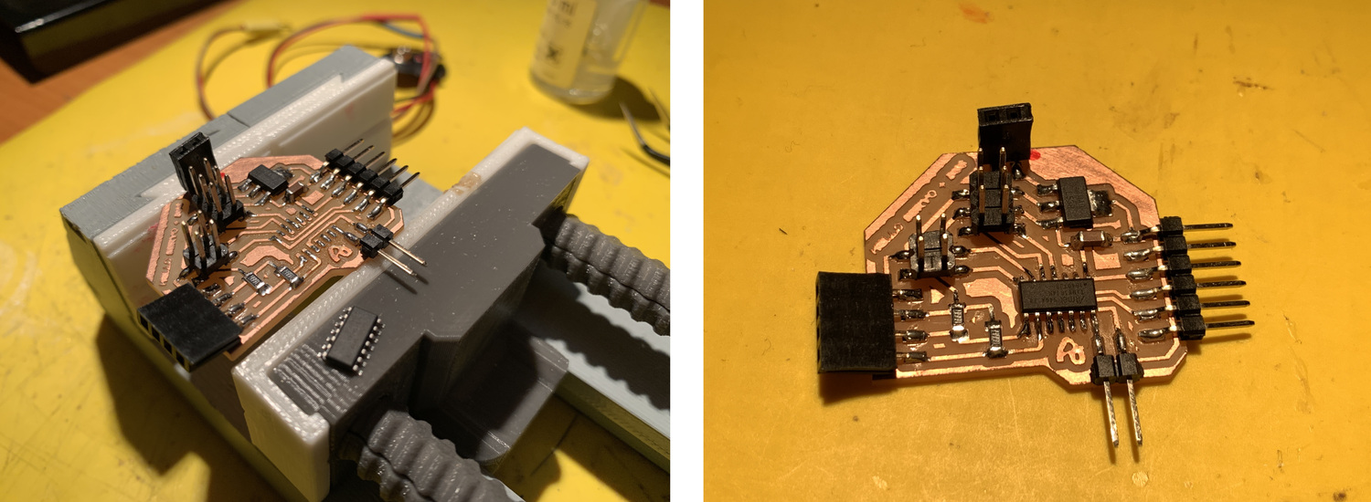
Once the new ATtiny1614 is soldered, I start programming it. This time I take the example of Arduino and modify only the output pin, in this case PA7 (Pin 3 of Arduino). I load the program and everything is correct.

And works 😊; It moves well and does not crash. 💪
//Modified by Adrián Torres Omaña
//Fab Academy 2020
//Fab Lab León

/* Sweep
 by BARRAGAN
 This example code is in the public domain.

 modified 8 Nov 2013
 by Scott Fitzgerald
 http://www.arduino.cc/en/Tutorial/Sweep
*/

#include

Servo myservo;  // create servo object to control a servo
// twelve servo objects can be created on most boards

int pos = 0;    // variable to store the servo position

void setup() {
  myservo.attach(3);  // attaches the servo on pin 3 to the servo object
}

void loop() {
  for (pos = 0; pos <= 180; pos += 1) { // goes from 0 degrees to 180 degrees
    // in steps of 1 degree
    myservo.write(pos);              // tell servo to go to position in variable 'pos'
    delay(15);                       // waits 15ms for the servo to reach the position
  }
  for (pos = 180; pos >= 0; pos -= 1) { // goes from 180 degrees to 0 degrees
    myservo.write(pos);              // tell servo to go to position in variable 'pos'
    delay(15);                       // waits 15ms for the servo to reach the position
  }
}
To check if it works perfectly, I load another program, this time so that two servos move at the same time in each output, both on PA6 (Pin 2 of Arduino) and PA7 (Pin 3 of Arduino). The program loads correctly.
Here the video of the movement of the servos. The first video is with 9V power from the battery.
This is powered from the FTDI, and it also works correctly.
And this is powered by both the 9V battery and the FTDI. No problem, both feeds can work at the same time.
//Modified by Adrián Torres Omaña
//Fab Academy 2020
//Fab Lab León

/* Sweep
 by BARRAGAN
 This example code is in the public domain.

 modified 8 Nov 2013
 by Scott Fitzgerald
 http://www.arduino.cc/en/Tutorial/Sweep
*/

#include

Servo myservo1;
Servo myservo2;
// create servo object to control a servo
// twelve servo objects can be created on most boards

int pos = 0;    // variable to store the servo position

void setup() {
  myservo1.attach(2);  // attaches the servo on pin 2 to the servo object
  myservo2.attach(3);  // attaches the servo on pin 3 to the servo object
}

void loop() {
  for (pos = 0; pos <= 180; pos += 1) { // goes from 0 degrees to 180 degrees
    // in steps of 1 degree
    myservo1.write(pos);              // tell servo to go to position in variable 'pos'
    myservo2.write(pos);
    delay(15);                       // waits 15ms for the servo to reach the position
  }
  for (pos = 180; pos >= 0; pos -= 1) { // goes from 180 degrees to 0 degrees
    myservo1.write(pos);              // tell servo to go to position in variable 'pos'
    myservo2.write(pos);
    delay(15);                       // waits 15ms for the servo to reach the position
  }
}
Conclusions.
It is strange that this has happened to me, but it could have been that the servo was blocked and it entered intensity by the signal pin of the ATtiny1614 (PA7) and something internally broke. The regulator was working properly and the voltages were correct.
What I have learned is that I must always configure the outputs in PWM for what I can use and that when I get the error in the terminal "UPDI not ok reinittialisation required" is that the ATtiny has died. 😣
Here is the files to download.
- Hello Servo Traces
- Hello Servo interior
- Hello Servo Schematic and Board ATtiny1614
- Arduino Program Hello Servo
- Arduino Program Hello 2 x Servos
Hello LED's
Design
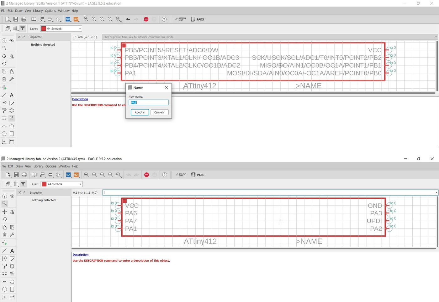
For the Hello LED I am going to use the ATtiny412, because I only need to light two LED's that I am going to use for the warning signs of the level crossing of my final project. To make the schematic the first thing I do is look for the footprint in the library, but there is no ATtiny412. Neither does Digikey or Octopart. So using Eagle, I edit an ATtiny45 and convert it to an ATtiny412 and save it in my library.
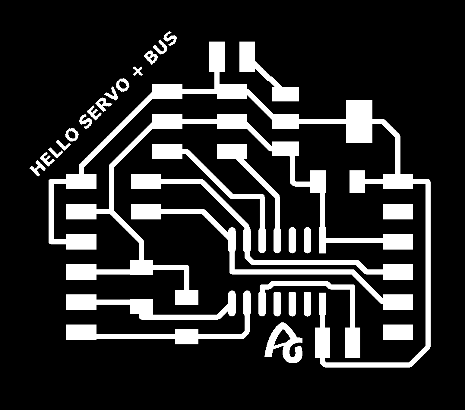
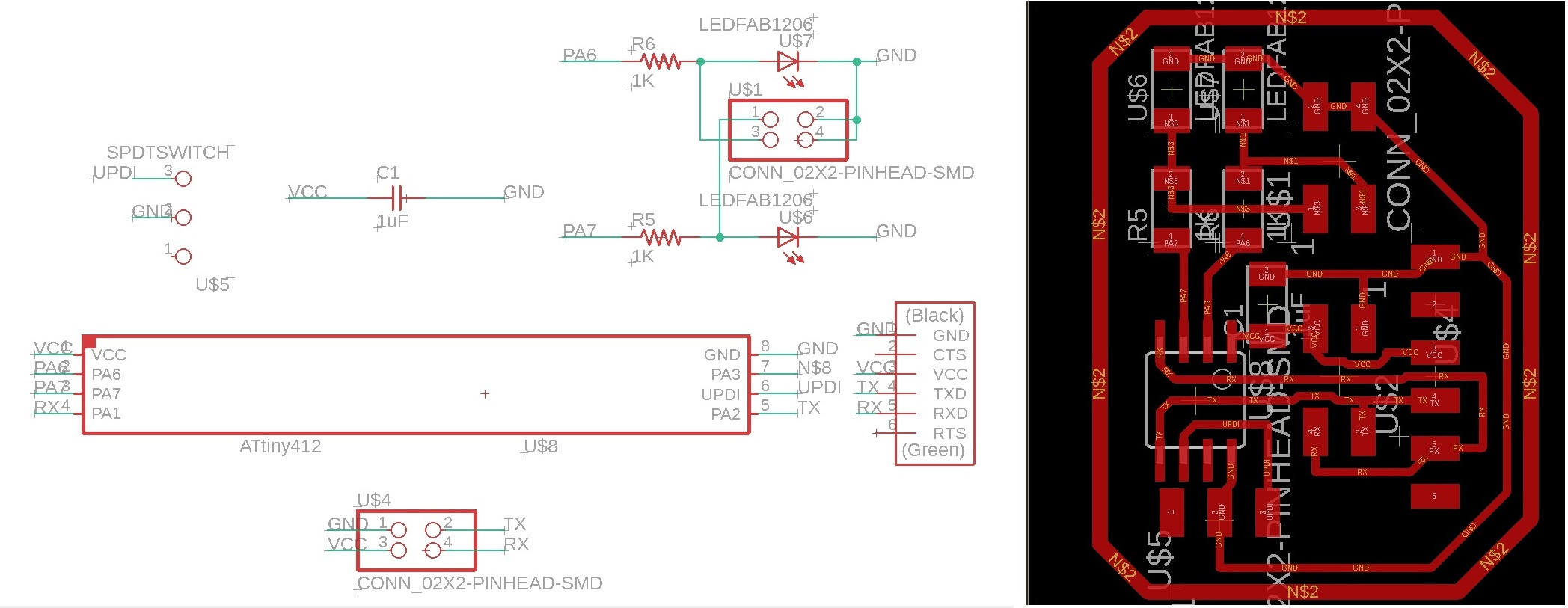
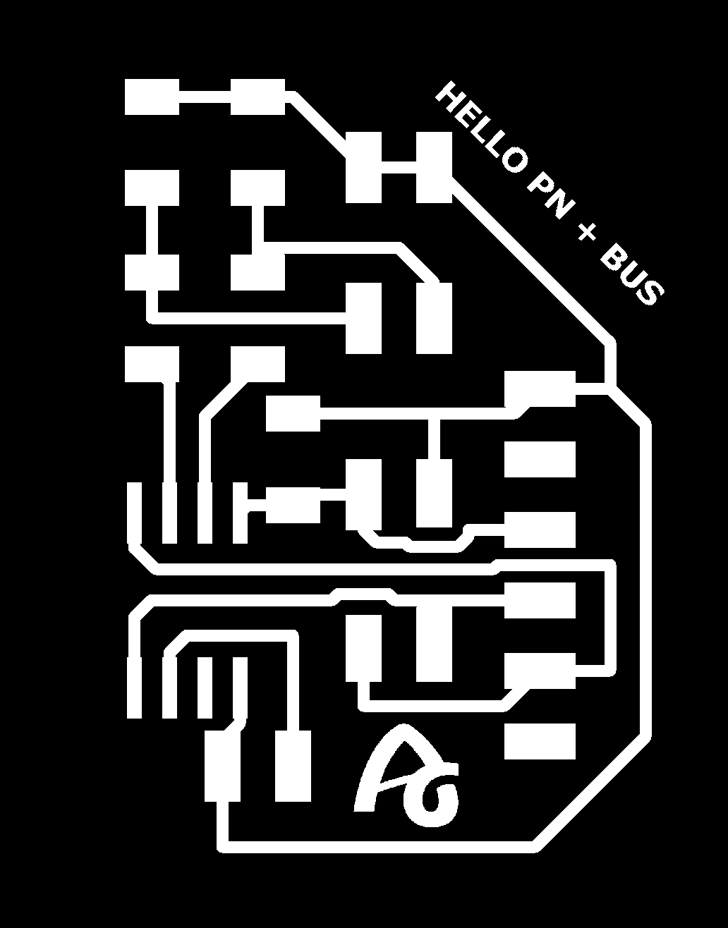
Once I have the ATtiny412 design, I do the rest of the circuit. In this case I am not going to use a voltage regulator, because I plan to power this board, through the Serial Bus because this board is going to be a slave. For the tests I will connect it through the FTDI. This is the schematic and the board.
Making
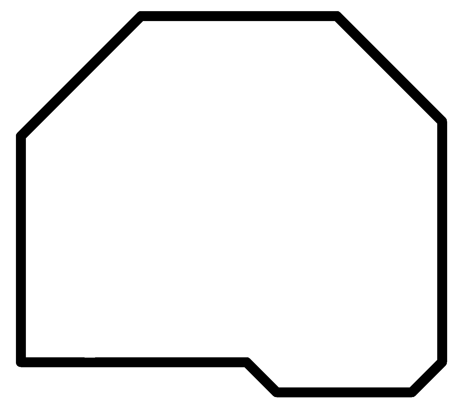
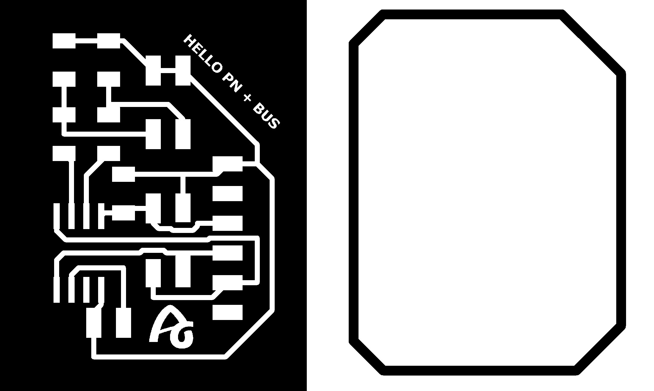
And these are the two images ready to use in the Modela.
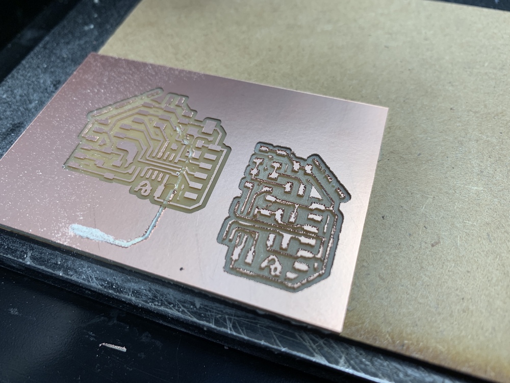
As with the previous board, I use CE Mods. And I try to reuse the board that went wrong, because it fits. But ... I am so "ruinas" (Spanish expression), the mill broke and I try to take advantage of it, leaving the board very skinned. 😬
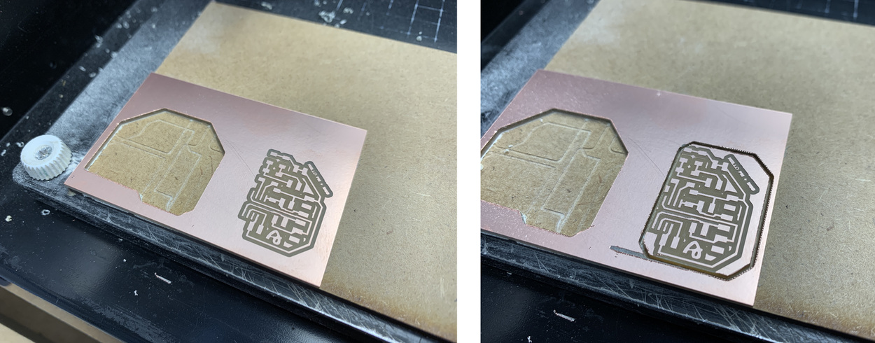
So the board that I was going to reuse at the end nothing. Sorry Nuria.😢 How did I start another new board for the previous board, because I ended up using it. I also repeated the displacement of the origin, in this case I had X = 48 and Y = 2; In order not to lose all the work, I move the origin by eye and place it at X = 50 and Y = 2. Even so, the board was a bit tight on the left side, but I managed to save it.
For this board this is the list of components for this board, an ATtiny412, the 1uF capacitor, the resistors 1K for the LED's, two red LED's and various connection pins.
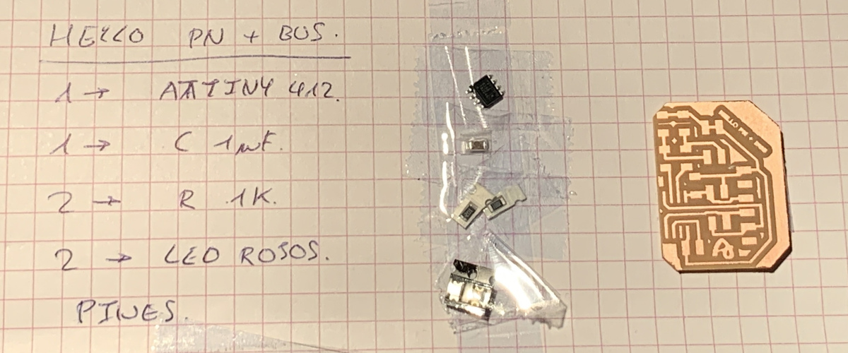
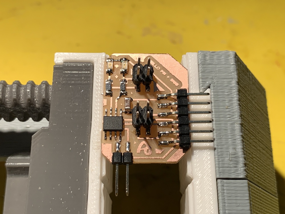
And this is the result of soldering, a tiny board and reused to the maximum the ATtiny412.💪 I have placed pins in the design to connect them to the signaling of the level crossing that I manufactured in week 05 of 3D printing.
This is the ATtiny412 soldering process video.
Programming: Arduino + Linux.
To program the Hello LED's board with the ATtiny412 I am going to use Arduino. In this case the LEDs are located on PA6 (Pin 0 of Arduino) and PA7 (Pin 1 of Arduino). The program is very simple, it alternates each LED with a certain cadence.
For programming I follow the steps as in week 08. I compile the Arduino program, copy the .hex file and paste it in the Pyupdi folder. Through the Pyserial and UPDI I program the board, and the programming is successful.
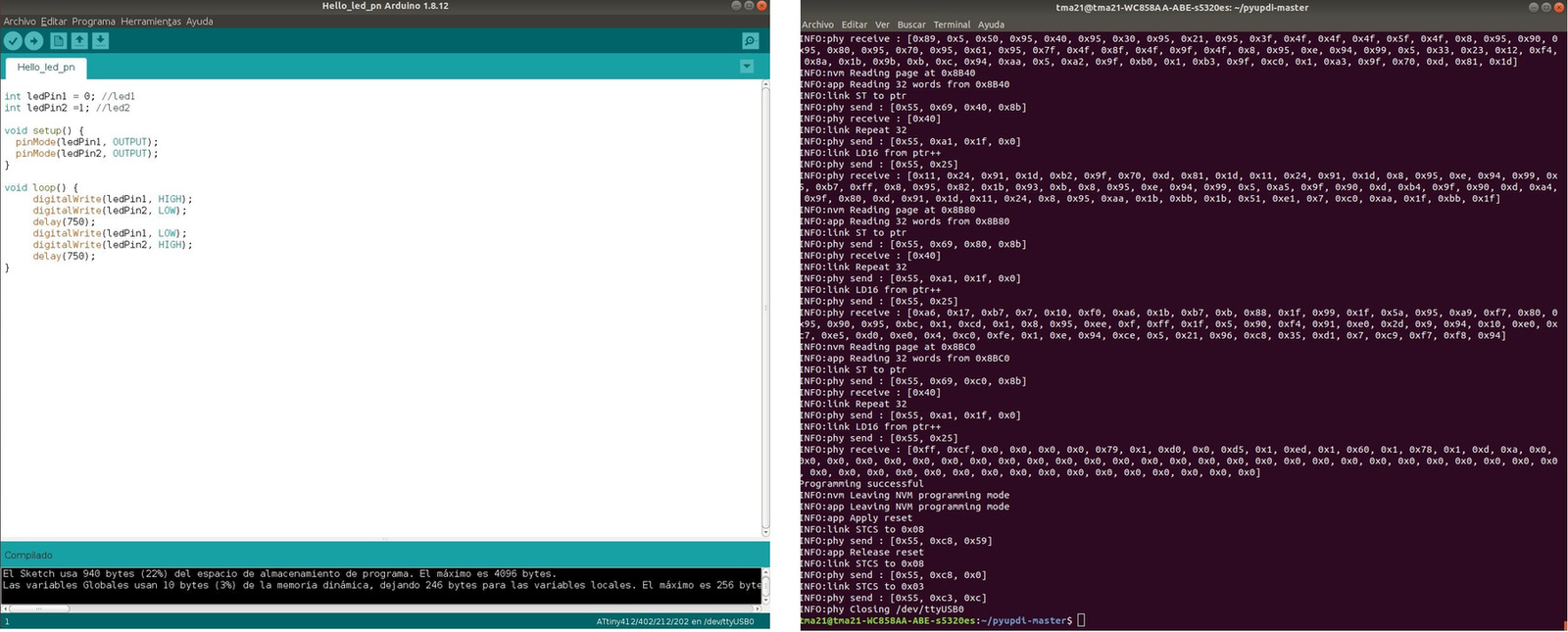
This is the result of programming.
//Adrián Torres Fab Academy 2020


int ledPin1 = 0; //led1
int ledPin2 =1; //led2

void setup() {
  pinMode(ledPin1, OUTPUT);
  pinMode(ledPin2, OUTPUT);
}

void loop() {
     digitalWrite(ledPin1, HIGH);
     digitalWrite(ledPin2, LOW);
     delay(750);
     digitalWrite(ledPin1, LOW);
     digitalWrite(ledPin2, HIGH);
     delay(750);
}
Here is the files to download.
- Hello LED's Traces
- Hello LED's interior
- Hello LED's Schematic and Board ATtiny412
- Arduino Program Hello LED's
Group Assignment.
Measure the power consumption of an output device.
The Group Assignment page is at the following link.
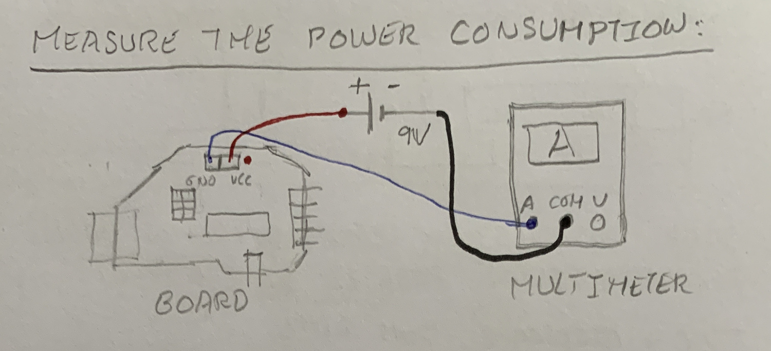
To measure the consumption of any electrical or electronic element, we will use a multimeter. Within the multimeter there is the Ammeter, which will serve us to know the consumption of a circuit or a component.
Important: We must always measure in series, that is, the circuit will be closed through the multimeter, so we must connect it correctly and always on a high scale or where we have the protection fuse (normally 10A).
The first thing I will measure is the total consumption of the Hello Servo board. This is how I connect it. The GND in the stack passes through the ammeter.
Here is the video of the measure. As the servo is also connected, the milliamps vary between 2.1 and 3.9 mA. To know the power, we use the following formula P = V x I.
The regulator has a voltage of 4.8 V and we take the consumption greater than 3.9 mA.
                            We pass milliamps to amps.
                            P = 4.8 x 0,0039 = 0,018 W.
Then I measure the servo consumption only. In the drawing I explain the connection of the ammeter. In this case I insert the ammeter in the VCC of the servo.
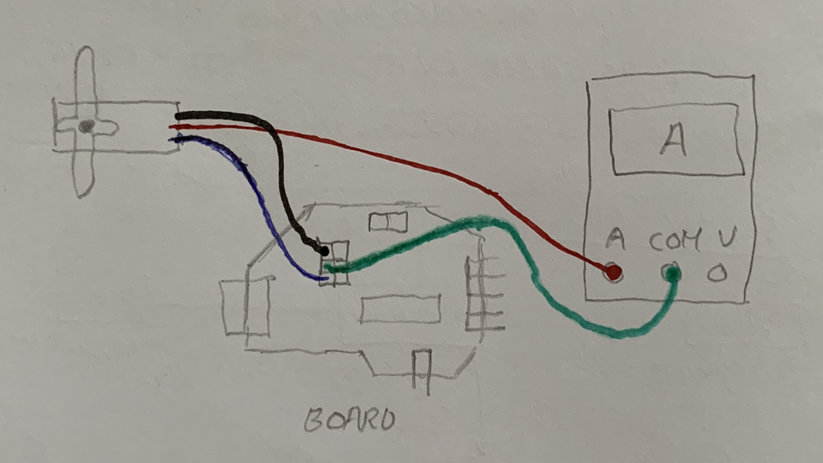
Here is the video of the measure. The consumption of the servo varies between 2.8 and 1.1 mA. To know the power, we use the following formula P = V x I.
The regulator has a voltage of 4.8 V and we take the consumption greater than 2.8 mA.
                            We pass milliamps to amps.
                            P = 4.8 x 0,0028 = 0,013 W.
As after having the problem with the ATtiny1614 that it did not move, as I have the oscilloscope at home it measured and gave me a continuous signal of 0.8V. Once the ATtiny was replaced, I measured the output pin of the microcontroller that goes to the servo to see the variation of the frequencies for the movement and it works correctly. Here is the video that shows it.
Final Project Test
The two outputs that I have created this week are very oriented to my final project, the servo and the LEDs. For this I want to test them to see if they work for me.
Hello Servo + Level crossing barriers
To adapt the servo to the base of the model, I was inspired by fastening the servos from the manufacturer PECO. Since I have the Prusa at home, I make a quick design to attach the servo to the base and have some regulation.
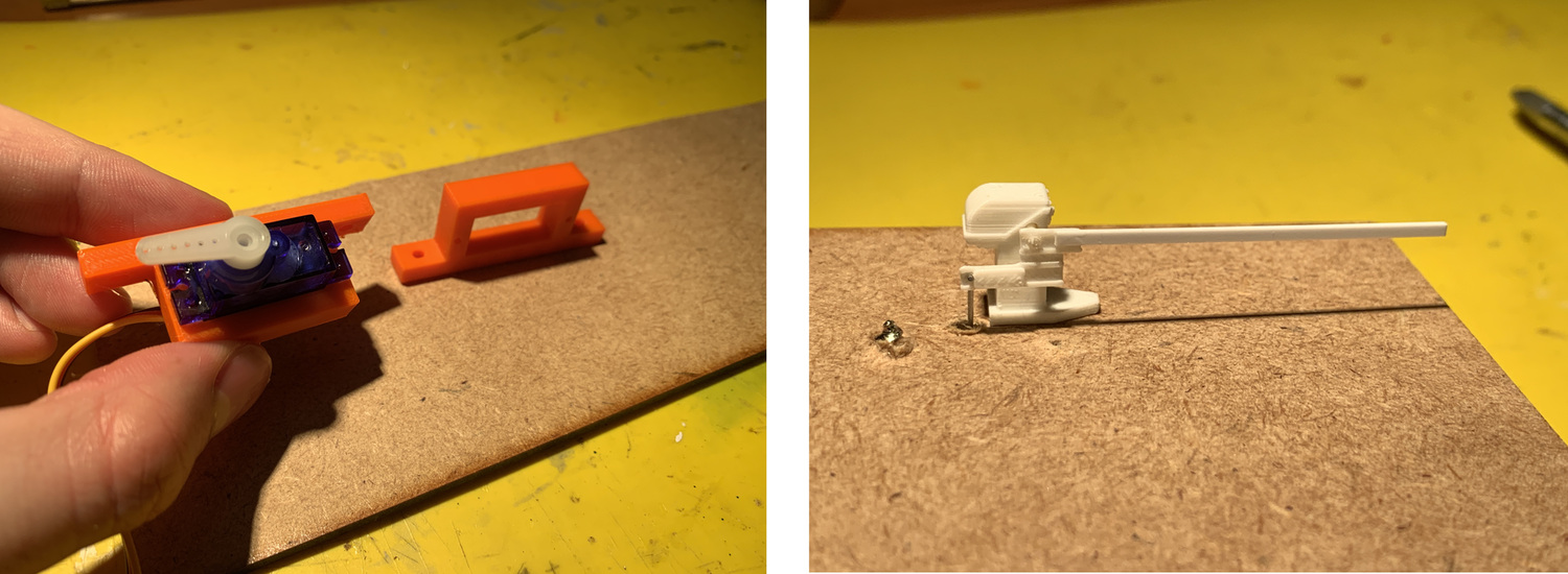
Using a wire, I move the barrier. But I realize that it twists a lot, because it is not making the turn on the axis, in the position that I have placed it it is out of phase. So a quick prototyping and I glue a piece of styrene and re-regulate everything. Now better.
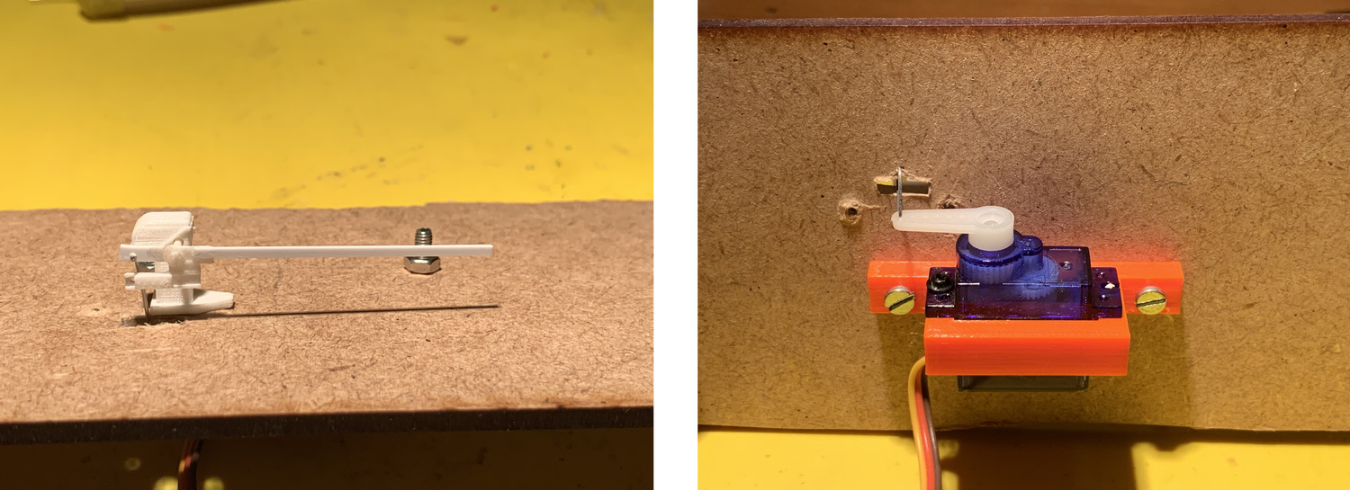
Once everything is adjusted, I load the following Arduino program and that's how it works in the video. Now I have to keep trying different speeds and positions.
//Adrián Torres Fab Academy 2020

#include


Servo myservo;  // crea el objeto servo

int pos = 0;    // posicion del servo

void setup() {

  myservo.attach(3);  // vincula el servo al pin digital PA7
}

void loop() {
   //varia la posicion de 8 a 37, con esperas de --ms
   for (pos = 8; pos <= 37; pos += 2)
   {
      myservo.write(pos);
      delay(80);
   }

   //varia la posicion de 8 a 37, con esperas de --ms
   for (pos = 37; pos >= 8; pos -= 2)
   {
      myservo.write(pos);
      delay(80);
   }
}
Hello LED's + Level crossing signals
When designing this board, place connectors to connect the level crossing signals. The program I use is the same as in this assignment.
Since the signal cables are so thin, I have a piece of rigid cable soldered and resistors to the 470 ohm LEDs. The circuit has 1K resistors, but I keep the resistance at 470 ohms because they are very small LEDs and I still damage them. Here the video of the operation.
LCD - I2C
01/08/2020
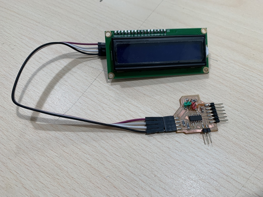
During the FabAcademy I bought several objects that I wanted to use, among them is an LCD module with interface for I2C communication protocol. In my case, I bought it through Amazon from AZDelivery, here is the link. This company has a multitude of very interesting tutorials, including that of the LCD module with I2C.
I will use the board that I designed for the Input with the phototransistor and that by including an I2C port I can connect the LCD. This is my connection of the two components.
When we use the I2C communication protocol, the first thing we must do is identify the different slaves that we connect to the bus. The same happens when we connect an input or an output, they have to have a name to identify themselves on the bus; is usually 0x... To do this I use Neil's program to see what number the I2C interface of the LCD uses.
//
// hello.I2C.ino
//
// I2C hello-world scanner
//
// Neil Gershenfeld 12/8/19
//
// This work may be reproduced, modified, distributed,
// performed, and displayed for any purpose, but must
// acknowledge this project. Copyright is retained and
// must be preserved. The work is provided as is; no
// warranty is provided, and users accept all liability.
//

#include Wire.h

void setup() {
   Serial.begin(115200);
   Wire.begin();
   }

uint8_t address,count;

void loop() {
   count = 0;
   Serial.println("start scan ...");
   for (address = 1; address < 127; address++) {
      Wire.beginTransmission (address);
      if (Wire.endTransmission () == 0) {
         count += 1;
         Serial.print("   found ");
         Serial.print(address,DEC);
         Serial.print(" (0x");
         Serial.print(address,HEX);
         Serial.println (")");
         }
      }
   if (count == 0)
      Serial.println("   no devices found");
   delay(1000);
   }
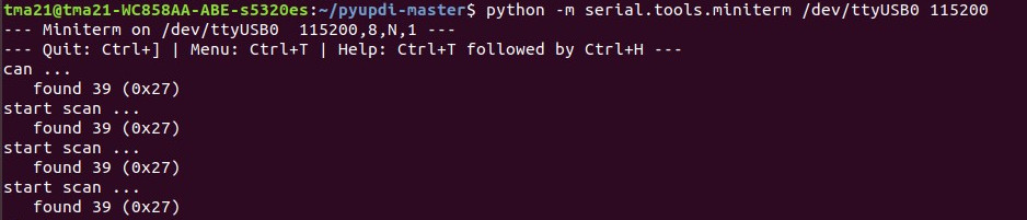
Once the program is loaded through the UPDI, we connect the LCD to the board and the FTDI to the computer. In the terminal we execute the instruction to see the number on the LCD. Listen the serial port python -m serial.tools.miniterm /dev/ttyUSB0 115200
In my case the number is 0x27.
Once I know what the LCD number is, I go on to test Neil's program, Hello_LCD.
//
// hello.LCD.I2C.ino
//
// LCD I2C hello-world
//
// Neil Gershenfeld 12/8/19
//
// This work may be reproduced, modified, distributed,
// performed, and displayed for any purpose, but must
// acknowledge this project. Copyright is retained and
// must be preserved. The work is provided as is; no
// warranty is provided, and users accept all liability.
//

#include LiquidCrystal_PCF8574.h
#include Wire.h

LiquidCrystal_PCF8574 lcd(0x27); // set LCD address 0x27
int count = 0;

void setup() {
   lcd.begin(16,2); // initialize 16x2 LCD
   //lcd.begin(20,4); // initialize 20x4 LCD
   lcd.setBacklight(255); // turn on backlight
   lcd.home(); // go home
   lcd.clear(); // clear display
   lcd.print("Hello World!"); // print text
   lcd.setCursor(0,1); // move cursor
   lcd.print("Count: ");
   }

void loop() {
   lcd.print(count);
   lcd.setCursor(7,1);
   count += 1;
   }
This is the video of the operation.
The next step is to connect the phototransistor to the board. With the sensor connected I want to map the values and at a certain value it will show to turn the light on or off. 😅
Using the following code, I initialize the LCD, map the sensor values and write to the LCD. I was inspired by the code with the following project that I found on the Arduino page, here is the link.
//Adrián Torres Fab Academy 2020
//Fab Lab León
//

#include LiquidCrystal_PCF8574.h
#include Wire.h

LiquidCrystal_PCF8574 lcd(0x27); // set LCD address 0x27

int sensorPin = 1;    // analog input pin to hook the sensor to
int sensorValue = 0;  // variable to store the value coming from the sensor


void setup() {
    Serial.begin(115200); // initialize serial communications
   lcd.begin(16,2); // initialize 16x2 LCD
   //lcd.begin(20,4); // initialize 20x4 LCD
   lcd.setBacklight(255); // turn on backlight
   lcd.home(); // go home
   lcd.clear(); // clear display
   lcd.print("Light!"); // print text
   lcd.setCursor(0,1); // move cursor
   //lcd.print("Lux: ");
   }

void loop() {
  sensorValue = analogRead(sensorPin); // read the value from the sensor
  sensorValue = map(sensorValue, 0, 1024, 1024, 0);
  Serial.println(sensorValue); // print value to Serial Monitor
   if (sensorValue <= 350) {  //if the value is equal to or less than 350
    lcd.clear();          // clear the LCD
    lcd.print("Light!"); // print text "Light"
    lcd.setCursor(4,1); //at the fourth cursor of the second line
    lcd.print("TURN ON"); //print text "TURN ON"
    delay(500);
    }
   else{                  //if the value is equal to or more than 350
    lcd.clear();          // clear the LCD
    lcd.print("Light!"); // print text "Light"
    lcd.setCursor(4,1); //at the fourth cursor of the second line
    lcd.print("TURN OFF"); //at the fourth cursor of the second line
    delay(500);
   }
}
This would be the phototransistor connection, just like in the Input Devices week.
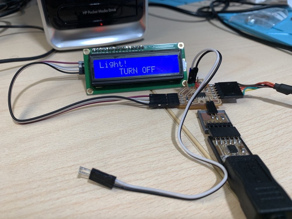
And this is the video of the operation. The code to download is at the bottom of the page.
Files
Find below the files that I made for this assignment.
- Hello Servo Traces
- Hello Servo interior
- Hello Servo Schematic and Board ATtiny1614
- Arduino Program Hello Servo
- Arduino Program Hello 2 x Servos
- Hello LED's Traces
- Hello LED's interior
- Hello LED's Schematic and Board ATtiny412
- Arduino Program Hello LED's
- Support 3D servo
- Arduino Program Servo Level crossing barriers
- Arduino Program I2C
- Arduino Program LCD Hello World
- Arduino LCD-Sensor