
Week 07. Computer-Controlled Machining
This week there are also two types of assignments, one group and one individual. In my case being alone in the Fab Lab, I do both.
- Test runout, alignment, speeds, feeds and toolpaths for your machine. ✔
- Make (design+mill+assemble) something big. ✔
- Explained how you made your files for machining (2D or 3D). ✔
- Shown how you made something BIG (setting up the machine, using fixings, testing joints, adjusting feeds and speeds, depth of cut etc). ✔
- Described problems and how you fixed them. ✔
- Included your design files and ‘hero shot’ photos of final object. ✔
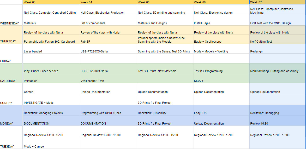
Like every week, my weekly schedule. 😊
CNC Machine.
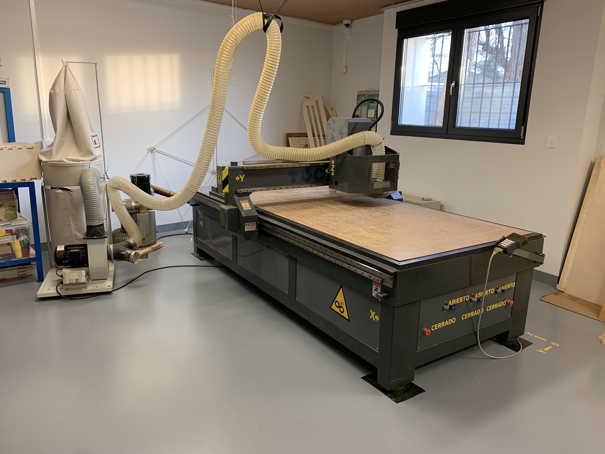
The CNC that exists in the Fab Lab León is the following model.
- Model: Milling Machine CNC TEC-CAM 500.
- Software: Aspire VCarve
- Work area: 1300 x 2500 mm
- Bridge height: 120 mm
- Maximum thickness of the material: ~ 40 mm (depending on the mill)
- This milling machine uses a vacuum table.
The CNC milling machine for me is the most dangerous machine 😬, due to the speed of movements and because the mill rotates at high speed and can break when it hits the material. That is why two people always work with the machine at the Fab Lab León. 👫 🤗The stickers of the directions of the axes and the origin of the machine I put them with vinyl, because I could not orient myself with the remote. 😅
Group Assignment
The Group Assignment page is at the following link.
Test runout, alignment, speeds, feeds of the machine
For the something big I am going to create a table for the coffee area of the Fab Lab León. This table has curved parts, so I'm going to do a flexibility test of the wood, the dogbone, the alignment and the chip speed.
The first thing I do is export part of the table layout that I designed in Rhinoceros in DXF. I'm going to test a dogbone that I have in my design. I open a new project in Aspire, where the first thing I do is configure the board that I am going to use and its measurements. For this exercise I am going to use a board 18 mm thick. When we import the vectors we have to center them on the material. It can also happen to us that the vectors are not joined, to join them we use the union tool.
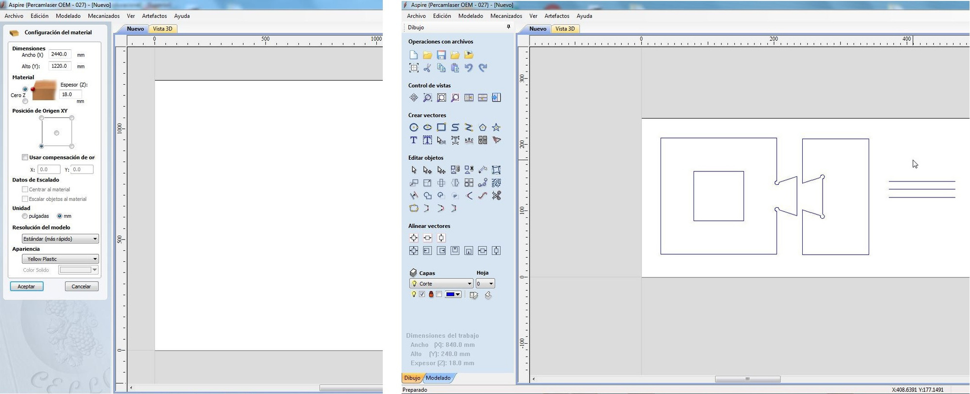
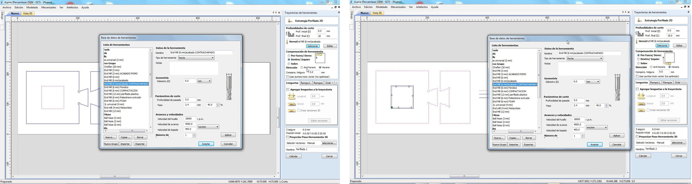
Once we have finished the design part, we move on to the toolpath, changing the menu to the right. If we click on a vector we can choose the toolpath: Profiling, Carved or Drills. For this test I am going to use the Profiling technique. For the 75 x 75 mm inner square I am going to use the Profiling but Inside, so that the final measurement is 75 x 75 mm. I choose the milling cutter of 6 mm of I finish of plywood with a speed of advance of 4000 mm / min that brings by default the program. For the exterior, I choose the Outline Profiling strategy and the same milling cutter with the same parameters.
Neil during class told us about chip load and feed rate. My instructor Pablo teaches me that on the Perez Camps website there are a series of tables and the formula to calculate the chip speed.
Feed rate (mm / min) = Chip load x flute number x RPM
In my case the chip load of the plywood with a 6 mm mill and a flute is from 0.28 to 0.33.
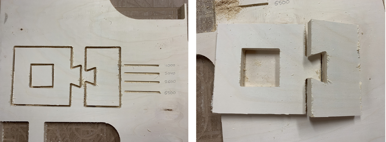
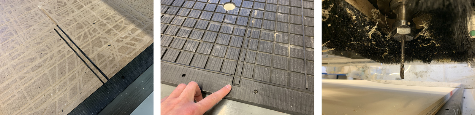
So apart from the dogbone I am going to make several lines at different speeds Profiling 5 mm above the line.
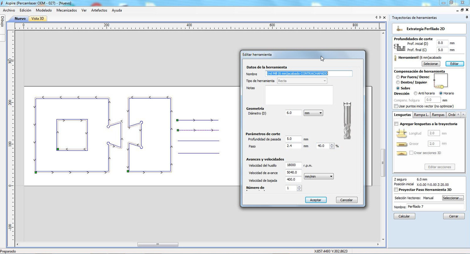
Once we have chosen the work strategy and the tool we can calculate the time and the final simulation. The Aspire Vcarve allows us to export our work in a multitude of GCODE formats, in my case for this machine I have to use the .TAP.
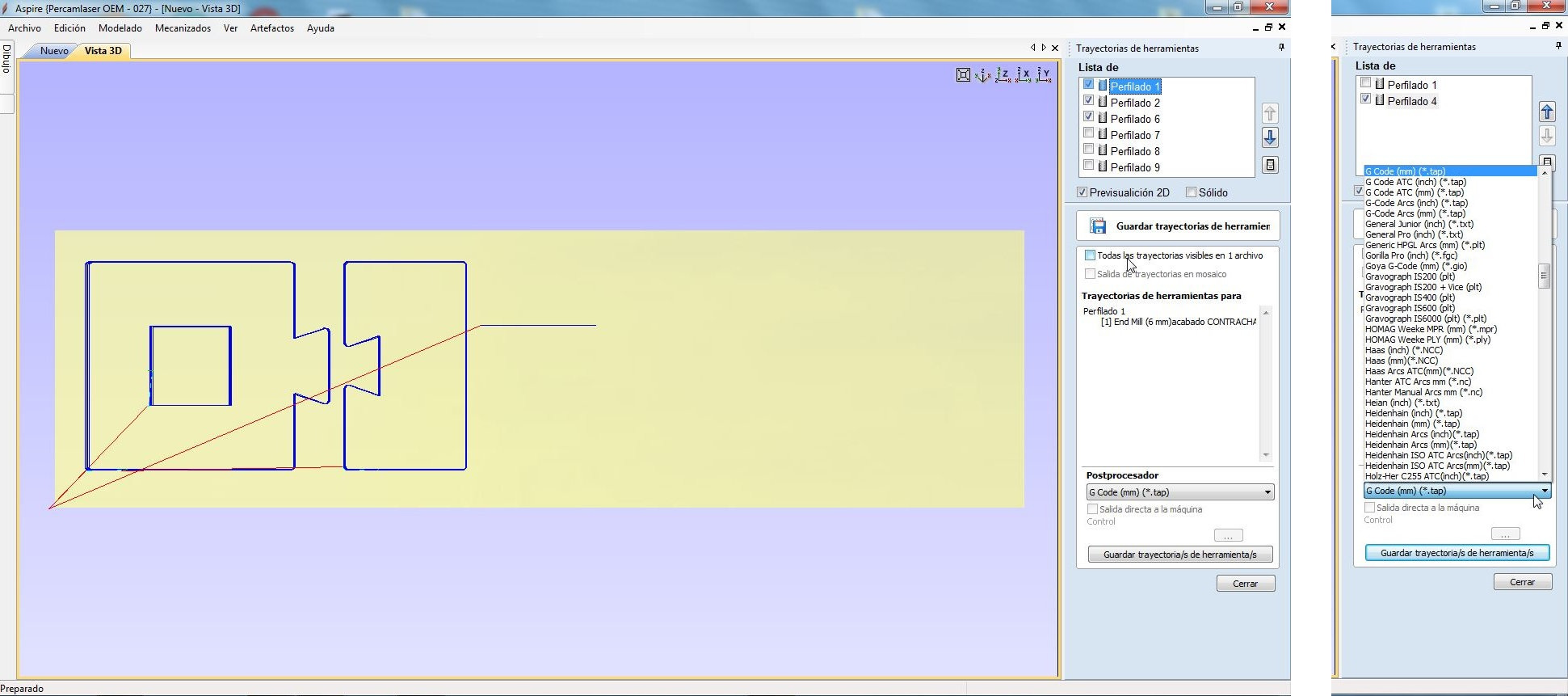
Once the .TAP file is generated, we save it to the pendrive. You have to be very careful with the pendrive; You can never be connected before turning on the machine and files cannot be overwritten, each file a new name. The following formula is usually used in the Fab Lab León, using the first three letters of the work and some number. For example INT101 or EXT101. Now it's time to get down to work, to the milling machine. 💪
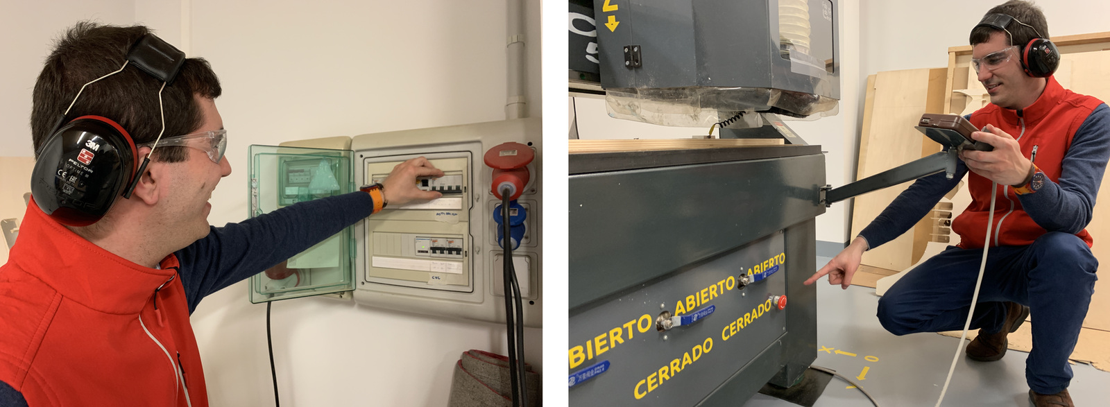
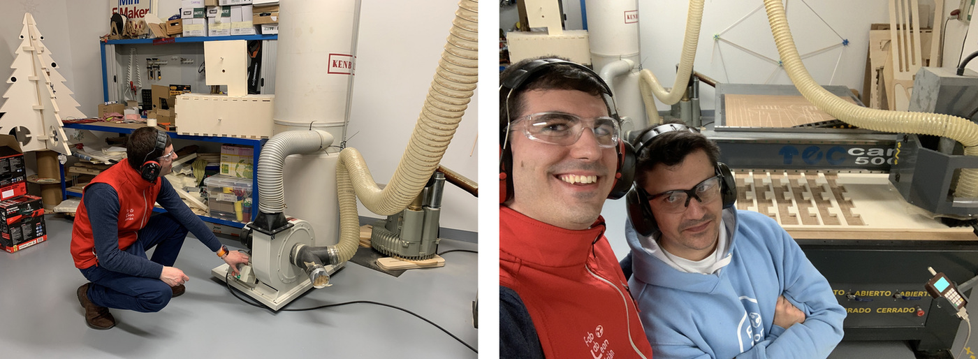
The first thing I do is find out where the electrical installation and the emergency buttons are.
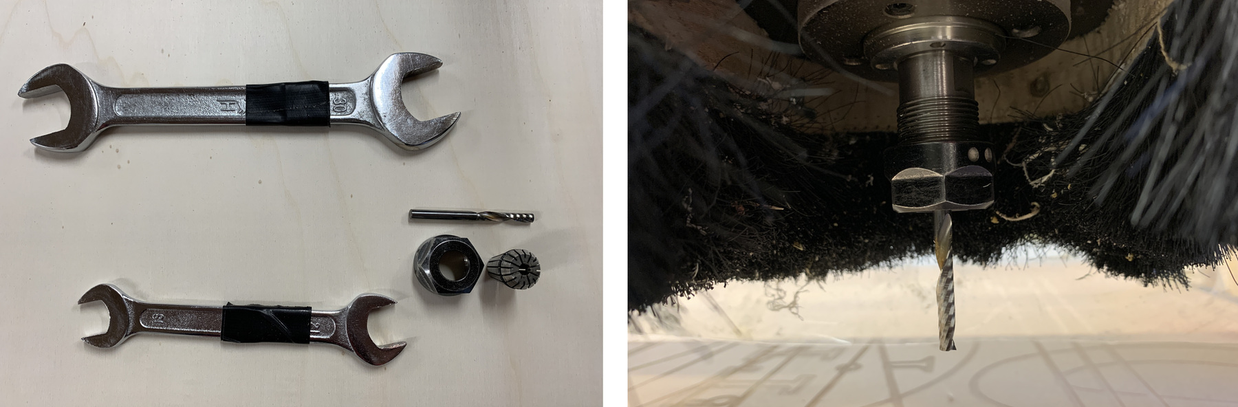
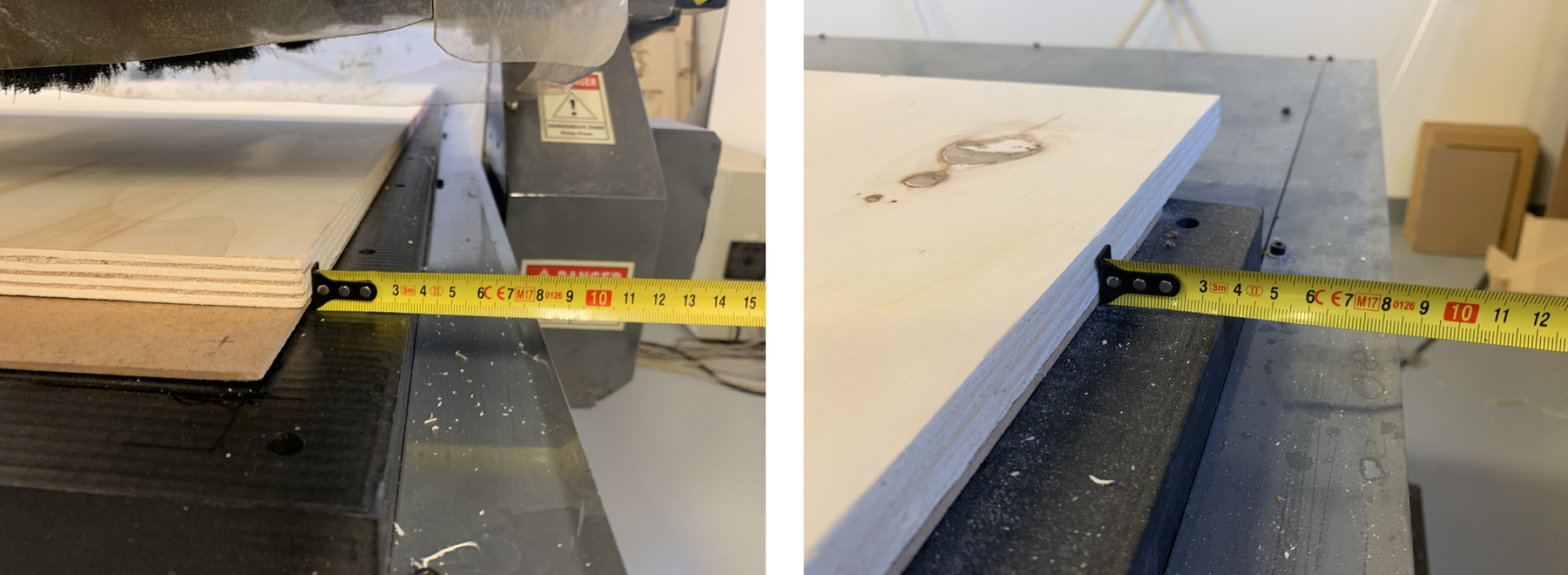
For this assignment I am going to use a single flute cylindrical mill with a diameter of 6 mm and a maximum cut of 30 mm. To install the mill you need two flat wrenches of 21 and 30 mm. Make sure that the cone fits inside the chuck perfectly. When you put the mill it has to be attached like the image; about 3-5 mm of stem before flute begins.
Once we have the mill installed, we place the board that we are going to use on the sacrificial board. By means of a meter I align the board to the machine, so that the works come out perpendicular to the machine. It is very important to do it at the beginning and at the end of the machine on the X axis.
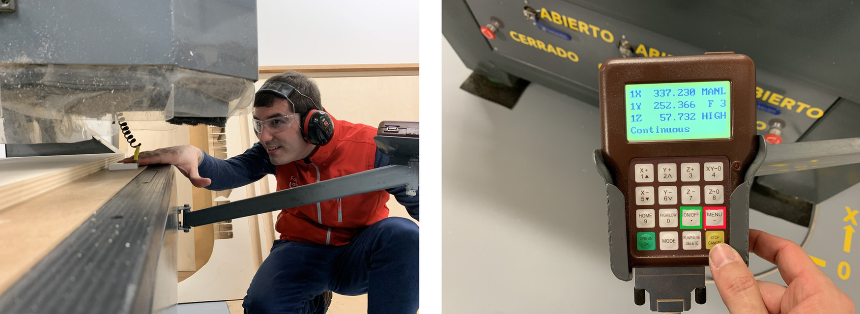
I turn on the vacuum of the vacuum table, it makes a lot of noise so you have to put on the ear protection. I have to calculate the thickness of the material with a metal probe. It is first measured on the sacrificial board and then on the material. With the two measures the difference is made. To measure this parameter, we will place the probe under the milling cutter and press the MENU key on the control first, followed by ON / OFF and the mill will slowly lower (this operation is the most dangerous, because if we do not do this sequence we can turn the mill ). I also set XY = 0. with the button XY->0.
A short video of the metal probe process
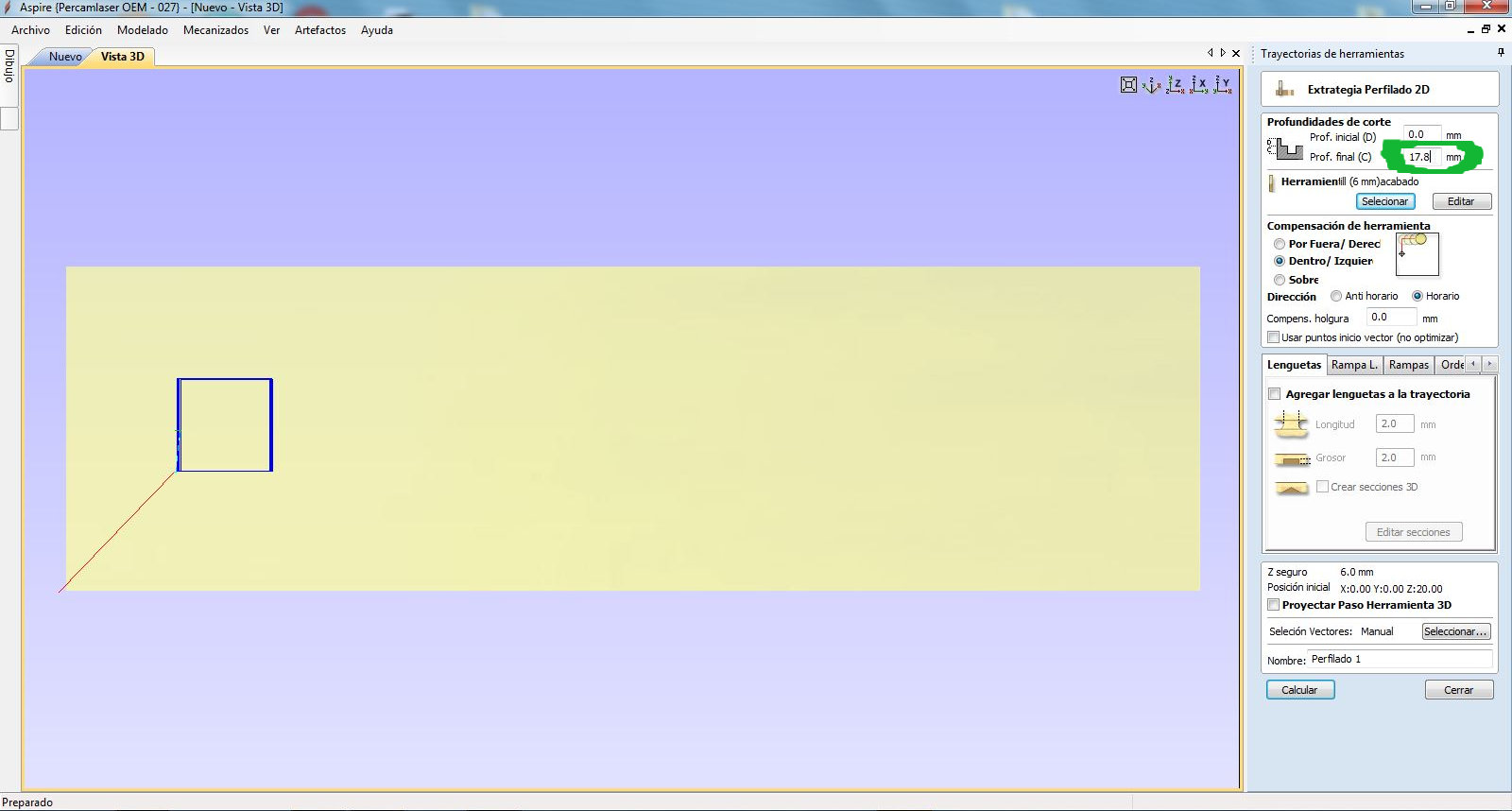
On this board the measure was Z0 = 74,736 and Z1 = 57,042. I make the difference and it gives me a result of 17.69 mm; rounding and put 17.8 mm. We have to modify this value in the toolpaths where we cut to the bottom of the material. We keep the trajectories on the pendrive.
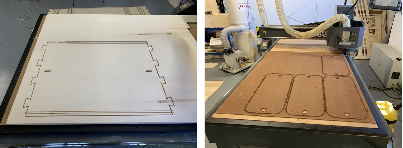
Once we have all the paths, we connect the pendrive to the command, press the RUN/DELETE button, choose U DISK and the file that we want to work on. We turn on the chip vacuum and watch the work, here with Pablo. 😍
Once the milling machine is finished, this is the result. It influences the wood and the diffraction of the wood grain, but at 6500 mm / min it generates less chip than at 4000 mm / min. Although the test has only been drilling 5 mm, I will continue to use 4000 mm / min, which is what has been used in the Fab Lab León with this wood. And the dogbone, because it does not work hehe, the piece does not fit because it is not well designed. 😬
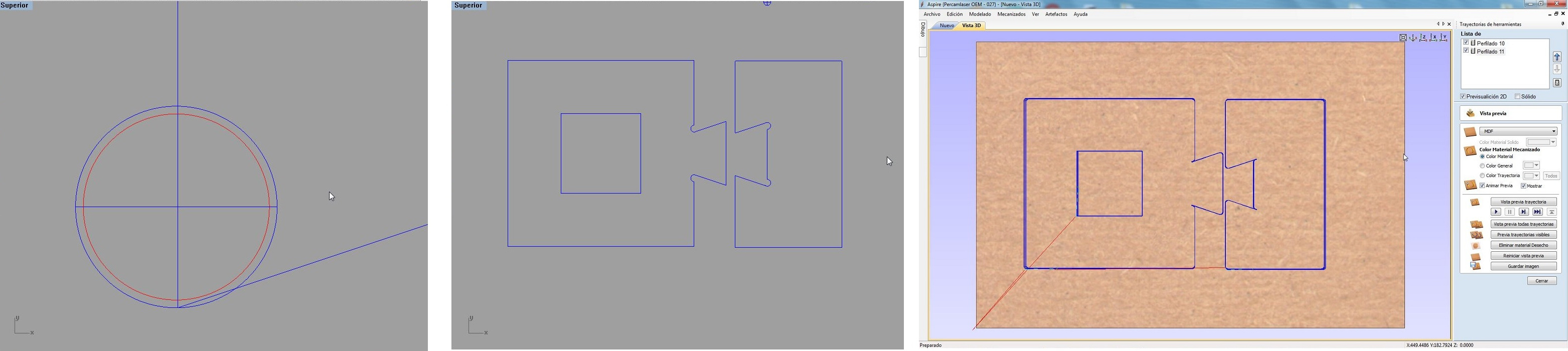
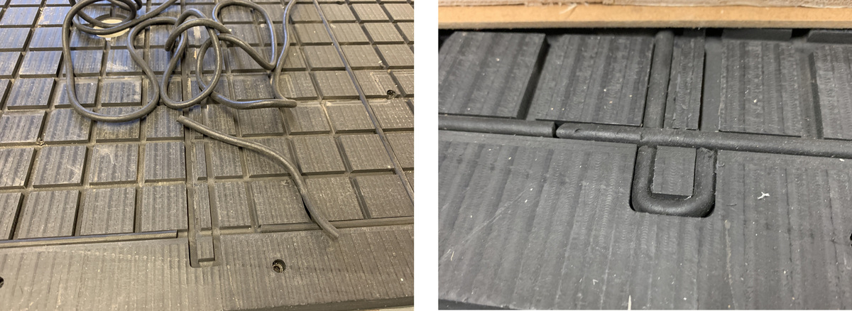
So we go back to design. Pablo explains to me that the mill must be able to pass through the lines, if the gap is less than 6 mm it will never pass. So I resize the dogbones so that the mill passes, I use 6.5 mm and 6.1 mm. In the design I simulate the mill with a red circle. I re-import the new design into the Aspire VCarve and repeat all the previous steps (trajectories, material thickness, XY -> 0). In the Aspire I can see the perfect path of the tool, and I see how the mill enters.
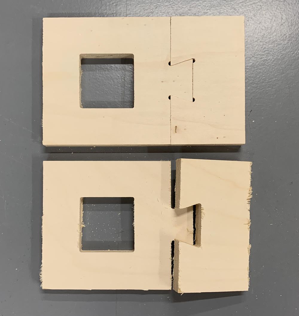
And this is the result, it fits perfectly, the same with enough pressfit but it fits. The comparative 😆
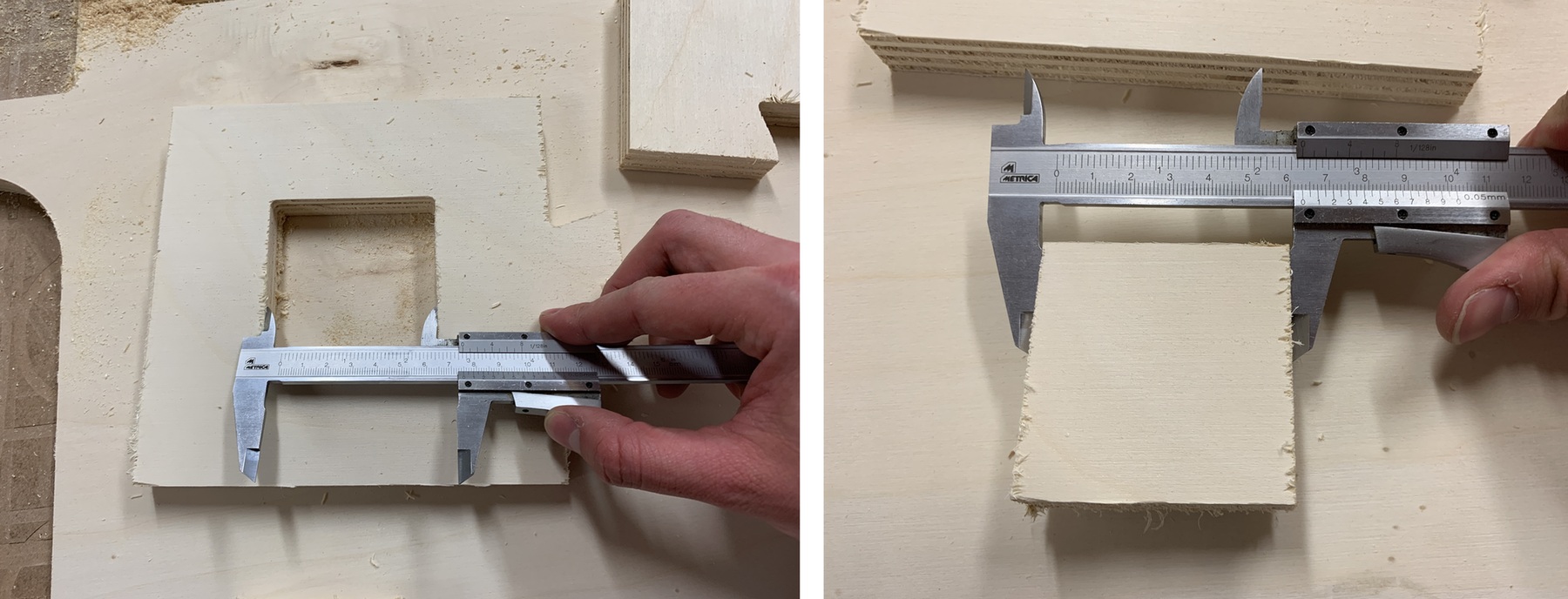
The measurements of the inner square are perfect, inside 75 x 75 mm and the small square is 63 mm (12 mm less by the 6 mm of the mill + 6 mm of the mill).
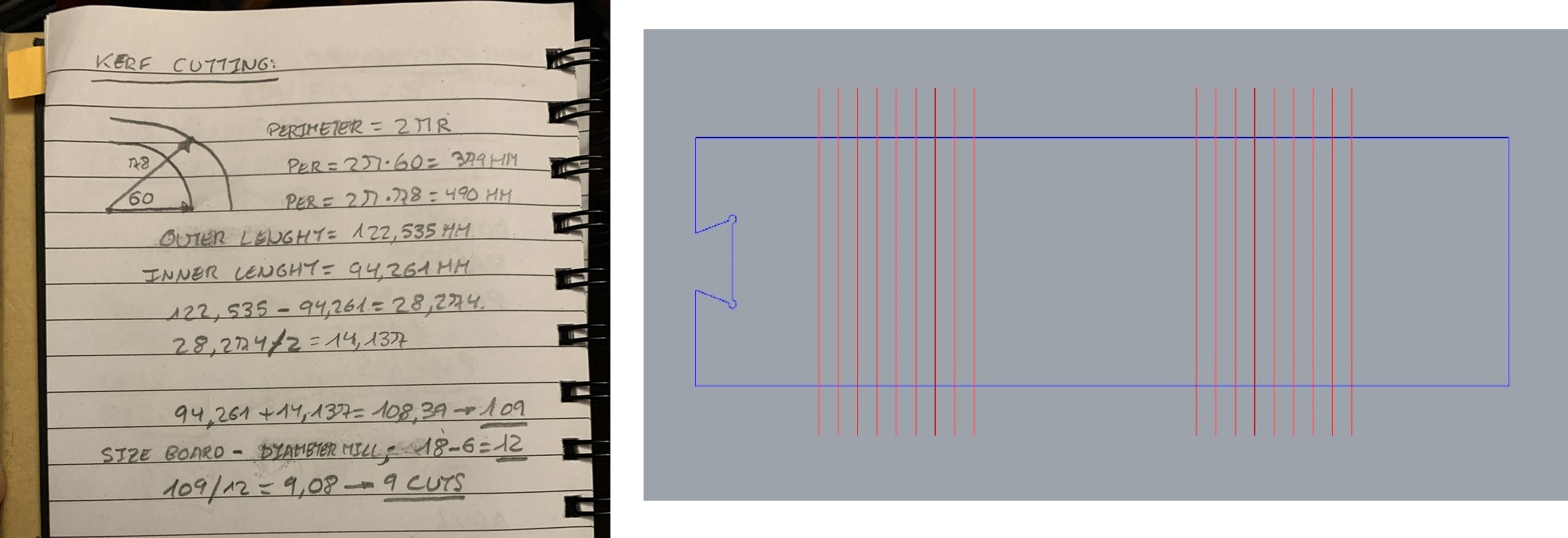
Another of the tests that I wanted to carry out is the bending of the wood, because the table that I am going to manufacture has curved parts. The technique is called Kerf Cutting. For this I was inspired by the design of Victoria Peredo from her CNC week at the Fab Academy.
The first thing I have to do is calculate to see how many cuts I have to make for my 18mm board and the radius of my curve. So I pass the measurements to the Rhinoceros design, I'm going to do a little test.
Update 03/17/2020. During the Regional Review, Edu Chamorro recommended that I look at the next web to do the Kerf Spacing calculations.
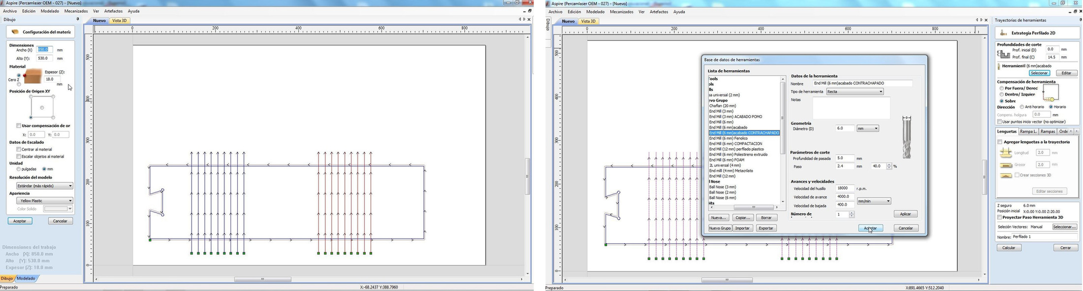
Once I have the design, I import it in DXF to the Aspire VCarve. I adjust the board to work, verify that the vectors are linked and move on to work strategies. For grooving I will use a Profiling on the line. I calculate the Z of the material and it gives me 17.50 mm thickness. I'm going to lower until I have 3 mm of wood left; I'm going to go down to 14.50 mm.
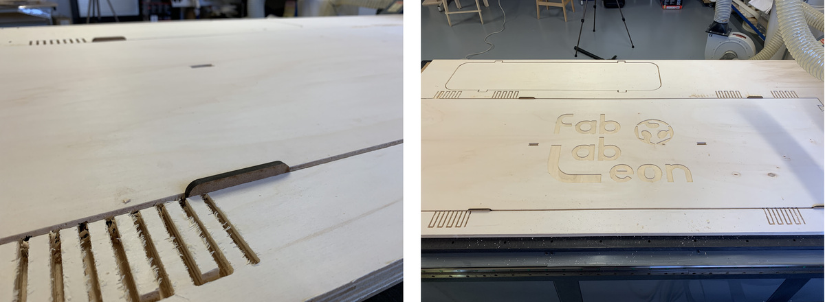
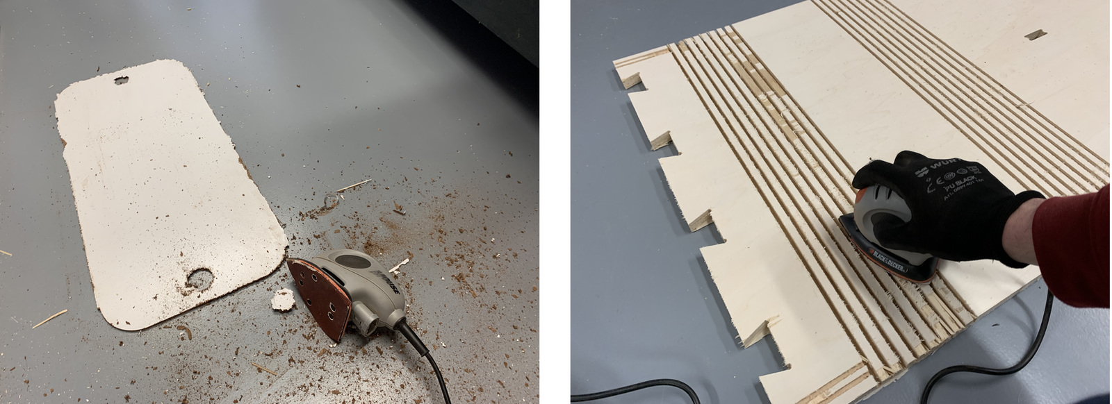
When I start the work at the CNC I notice that the wood begins to splinter, and it is from the direction of the wood grain. This happens a lot in plywood. So when it ends there is no other choice than sanding a bit and removing the chips.
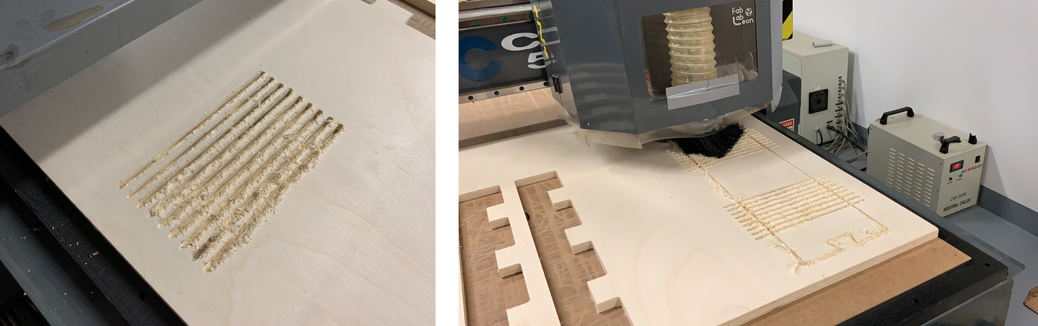
This is the video result, it is incredible how you can bend the wood, I am looking forward to making the table. 🤗 I break a bit and I think it could be due to the depth of the cut or the type of wood and the direction of the grain.
Here is the file with the Tests.
Make something big
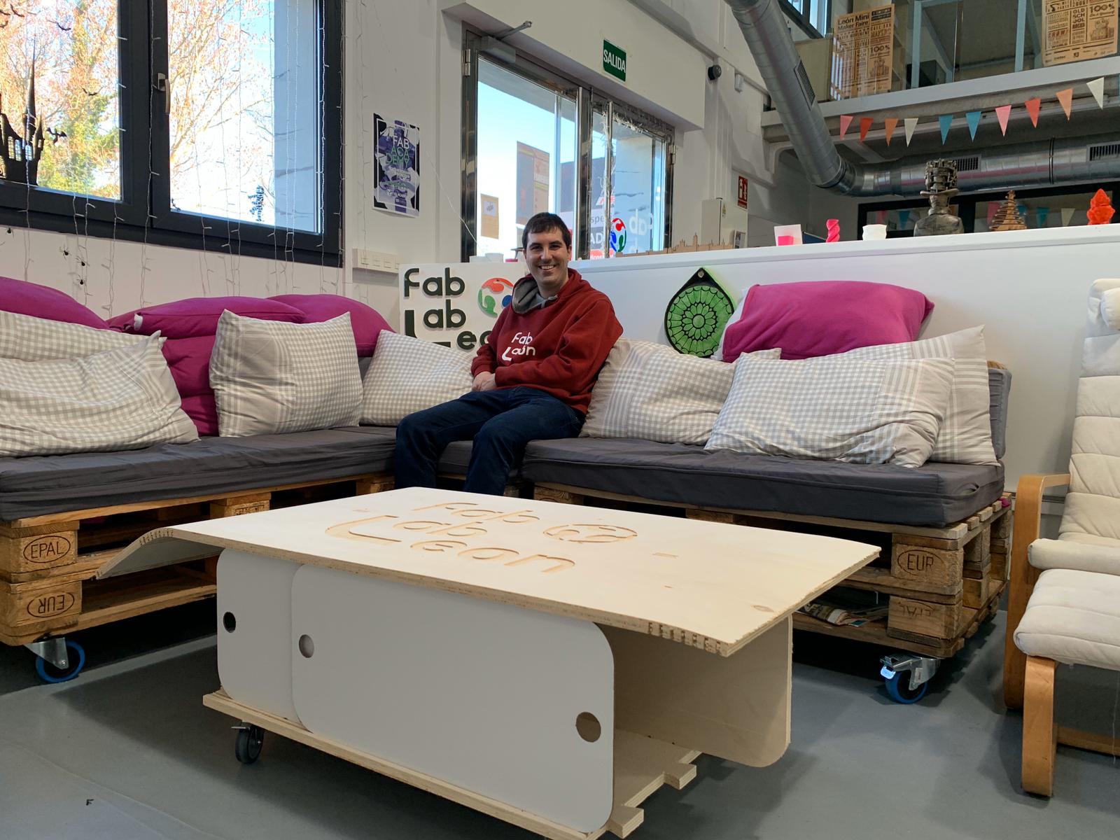
As I said at the beginning, I want to make a table for coffee at the Fab Lab León. During the summer when the Fab Lab closes we make improvements to the space. We build the cafeteria area with pallets, and the table is not practical.
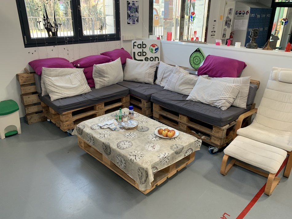
So through Rhinoceros I design a table inspired by the TV stand that Victoria Peredo made. I want a table that has sliding doors so that I can store different items in the cafe as well as magazines or newspapers.
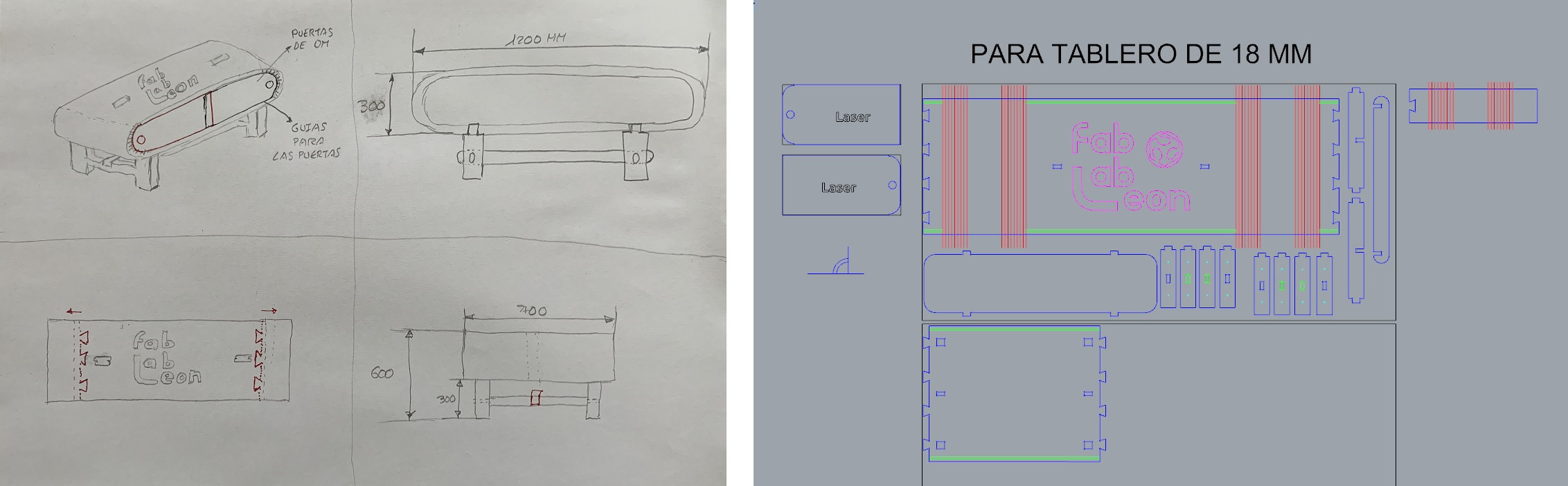
Speaking with Nuria and Pablo about the design, Pablo tells me that all the furniture in the Fab would be better if they had wheels, in order to move them better. Nuria recommends that I make the doors bigger so they can move sideways. But I have a problem because I can no longer cut the doors on the laser. Pablo tells me that he has a white lacquered DM board that I can mill at the CNC. Challenge accepted. 💪
This is the design; I need to use two 18mm plywood boards and one 3mm white lacquered DM board for the doors.
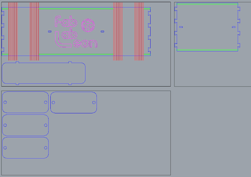
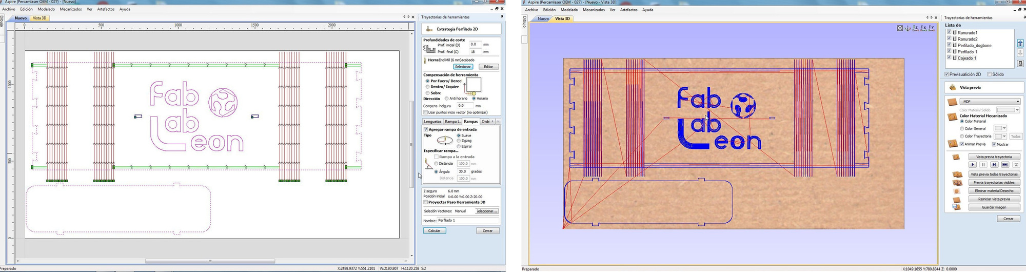
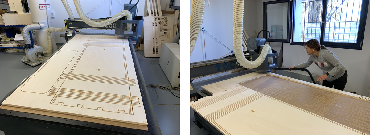
So I import board to board via DXF to the Aspire VCarve. I center the design on the board and calculate all the trajectories. First I was going to make a profiling on the line of the bending (I'm only going down to 3.2 mm), then the grooving for the sliding doors, the dogbones and finally the external profiling of the piece. I have to turn it to make the logo casing (the casing I am going to do with the same mill of 6 mm going down only 3 mm).
Today Nuria accompanies me in milling the table. 😘
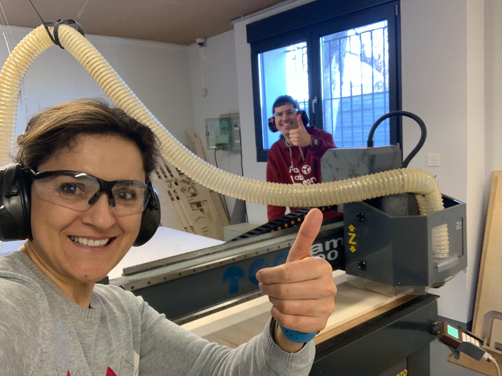
I start as the previous steps to mill the design, when suddenly the CNC starts to sound strange and it stops automatically. I have milled the vacuum table. The mandrel mill was loosened and the vacuum table was cut. 😭😭😭
Fortunately, Nuria was with me, otherwise I die. 😣 It is time to repair the vacuum table, reinserting new tires and replacing the sacrificial board.
Once the scare is over, I go back to redoing the whole process and looking at how the mill works at all times. This is the result of the first board, but I have to turn it over to do the logo carving. Thanks Nuria for helping me clean up. 😘
Once turned I adjust the board with 6 mm wedges so that the piece does not move and I start the carve. It has been perfect. Later with the laser I will cut the letters and the logo in colored methacrylates.
Once the main board is finished, I cut the base with the same parameters as the main one. For the doors I use 3 mm thick white lacquered DM. I recommend milling upside down to avoid bursting the lacquer. I use the parameters of the Compaction cutter, 3000 mm / min of advance speed. It is quite irregular and is a very dirty material.
Here is a video of the milling process of all the pieces.
When I have all the pieces ready, with the sander I remove shavings and sand the edges of the woods. How dirty is the DM. 🤮
The time has come, it's time to set the table. But ... as you can see in the video, my table breaks in the folding area. 😢
Nuria has told me that it has surely broken because the wood grain is in the opposite direction, and for not going deeper (for fear, going deeper to 3, 2 mm and I think I made the mistake). Also wetting the wood can work.
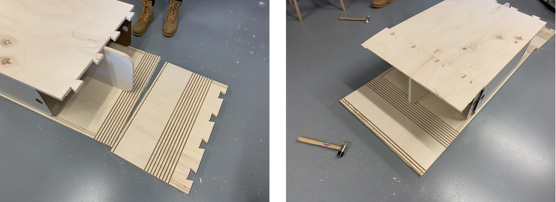
Although it was broken, Nuria told me to put the wheels on to see that they could hold and if it moved easily.
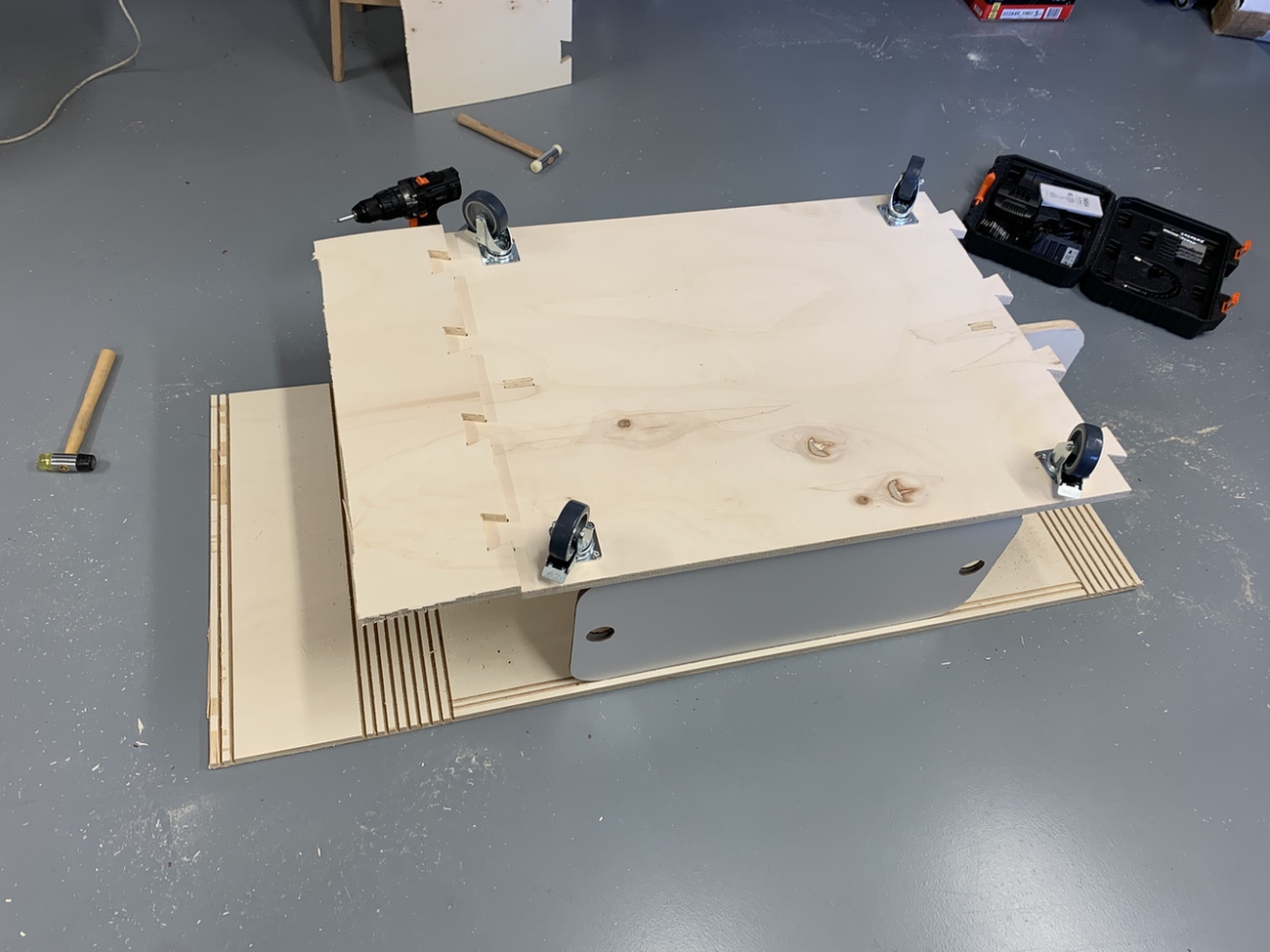
And this is all up to here, because the coronavirus has arrived and we cannot work several people in the Fab Lab León at the same time. Have to wait... 😢😷
This is the file with the new changes, the part of the carve separated from the parts that bend. Fab Lab León Table.
Extra Credit. Venice in gondola. ⛵
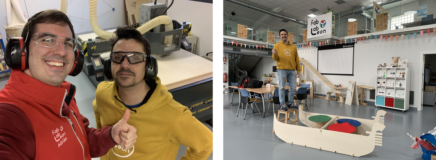
On January 11th we celebrated a birthday party 😍 at the Fab Lab León for our beloved Nuria. The theme of the party was beautiful Venice. So we got to work on the scene, and made a gondola with the CNC milling machine.
So Pablo and I got to work creating a gondola with the CNC. Designed in Rhinoceros, with dogbones to fit the pieces. Pablo is a perfect gondolier. 😜
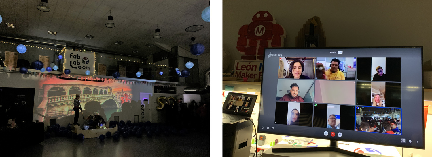
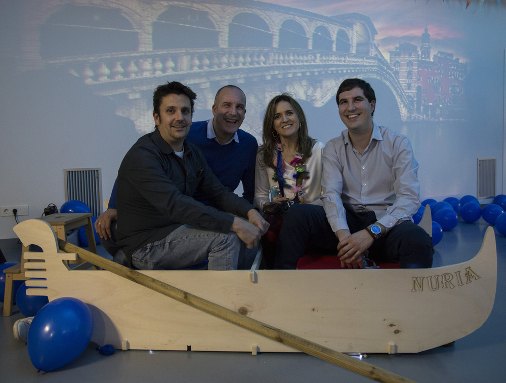
And the day of the party arrived. Nuria was not expecting it, we even made a conference with the #fablabnetwork (thanks to Fran, Montse, Anastasia, Luciana, Jean-Luc, Aristarco, Claudia, Santi ... for connecting).
And this is my C(u)ore, thanks guys I love you very much. Congratulations Nuria, you deserve everything and we love you. 😍
Here is the file of the Nuria Gondola.
Final Project
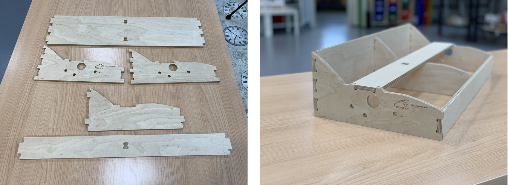
Thanks to the advice of my instructor Pablo, I decided to CNC mill a wooden frame of the model, using lace and dogbones. Using Rhinoceros design the frame following Maquetren's standards. I have milled it in 9mm thick plywood. Once the parts are assembled, this is the result of the module.
Within Project Development I have a section where you can see the file and the milling process, if you click on the following link you can see the result.
Review of the class
During the review of this class I volunteered with the problems with the CNC and the gondola in the minute 1:14:00. 😊
20200318 Computer Machining review from Academany on Vimeo.
Files
Find below the files that I made for this assignment.