
Project Development
This is the process of my final project. I show at first the three slides you create. From the skecth where I had the final project proposal, through the slide I did for Invention, Intellectual Property and Business Models and the last one for the Final Project Presentation.
I hope you enjoy my project as I have done making it. 🤗
About the following questions in this assignment.
- What tasks have been completed, and what tasks remain?
- What has worked? what hasn't?
- What questions need to be resolved?
- What will happen when?
- What have you learned?
Well, it is a bit complicated to answer all the questions at the same time, because in each week that I have worked on the project I have been documenting what I have learned, the errors I have had, how I have been solving them and if I have answered my questions.
At the bottom of the page you can find the files to download.
Week 01. Sketch
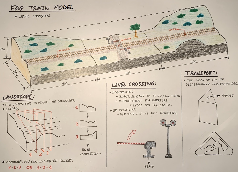
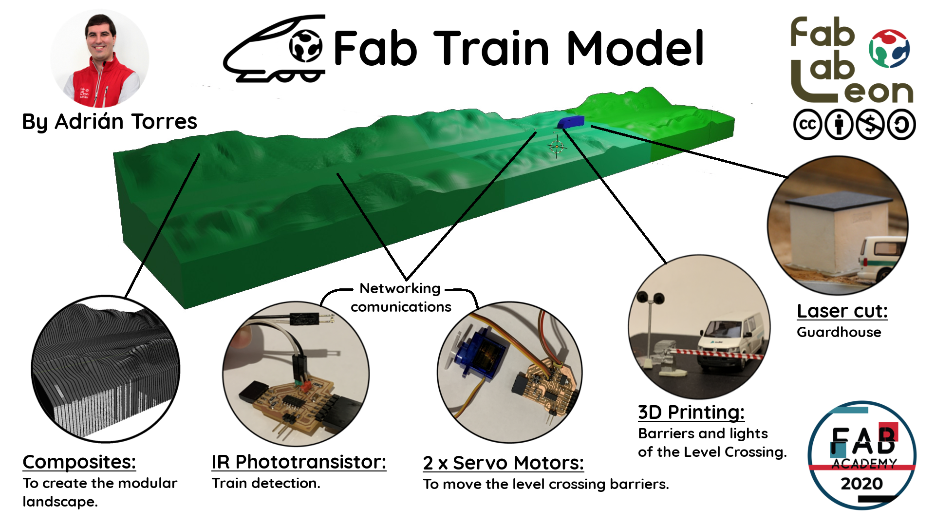
My idea for the final project is to build a model using composites to model the terrain. Also that a level crossing works before the passage of the train.
The frame of the model will be built in wood (the perimeter). For the landscape until now we used polystyrene that we carved with a cutter and then put glue and paper. In the Fab Lab my instructor Nuria had taught me several examples of the use of composites. I plan to mill the polystyrene with the shape of the desired landscape, but slice it. This allows me to make different landscape combinations and recycling the milled polystyrene model.
The model simulates a level crossing system. The system detects the arrival of the train by sensors and communicates with the actuators that move the barriers and the sequence of lights. To detect the train I plan to use light sensors or similar. When the train passes the sequence will be as follows:
- Detect the train. The lights begin to flash and slowly lower the barriers of the level crossing.
- When the train has just passed just above the level crossing, the system is deactivated, the lights go out and the barriers rise.
There is a sensor on each side of the level crossing to detect the direction of the train. To activate the movement of the barriers I will use servos.
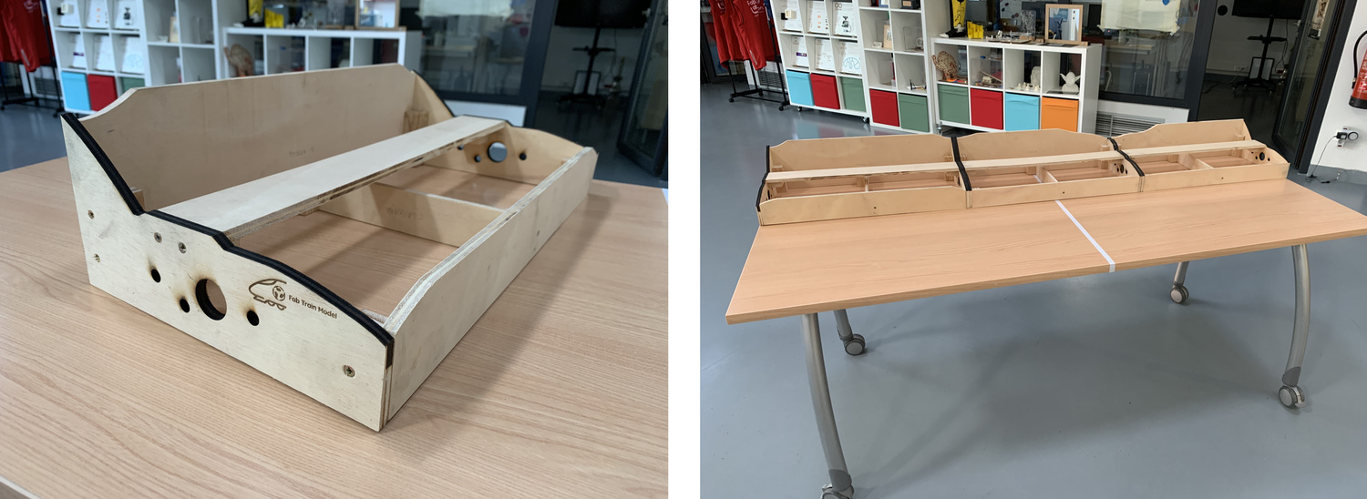
For the transport of the model, being modular it is disassembled into three pieces of the same size. With two boards at the ends you can hold the three modules and transport them at once.
Week 02. Design of the level crossing barrier
As my final project represents a level crossing, the barriers are made in 3D Printing. This level crossing model is real and exists in Spain. I take the measurements of the original and scale it to 1:87 (H0 Scale) which is the scale that I will use in the model.
The files: Level Crossing Freecad File and Level Crossing STL
Week 05. 3D Printing. Barriers and level crossing lights
During the design week, design the barriers and lights using FreeCad. Now is the time to print it. As they are small pieces I have ensured that they are not less than the width of the extruder 0.4 mm and that I can make layer heights of 0.1 mm. In this case I will use the Prusa and the Makerbot to make the pieces. It does not take more than 15 minutes the largest that is the barrier engine.
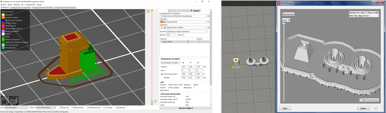
Sometimes it doesn't work out at first, and you try to save time and it's not worth it. Putting some pieces together, I have extrusion problems, because when the piece is so small when it jumps from one to another, the PLA cools and looks bad. So I separate the pieces. Here the progression. I have printed several spare parts and on both machines, so the color of the PLA may be different.
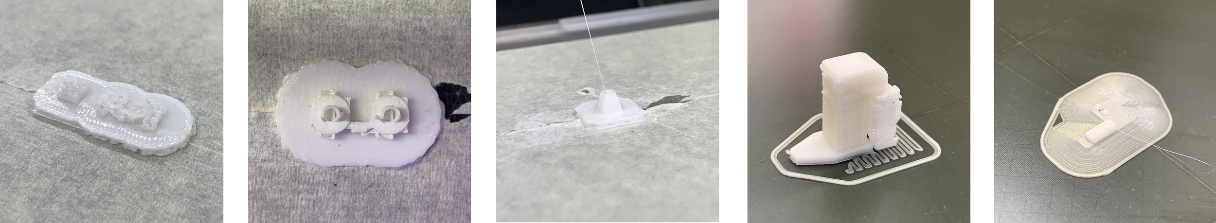
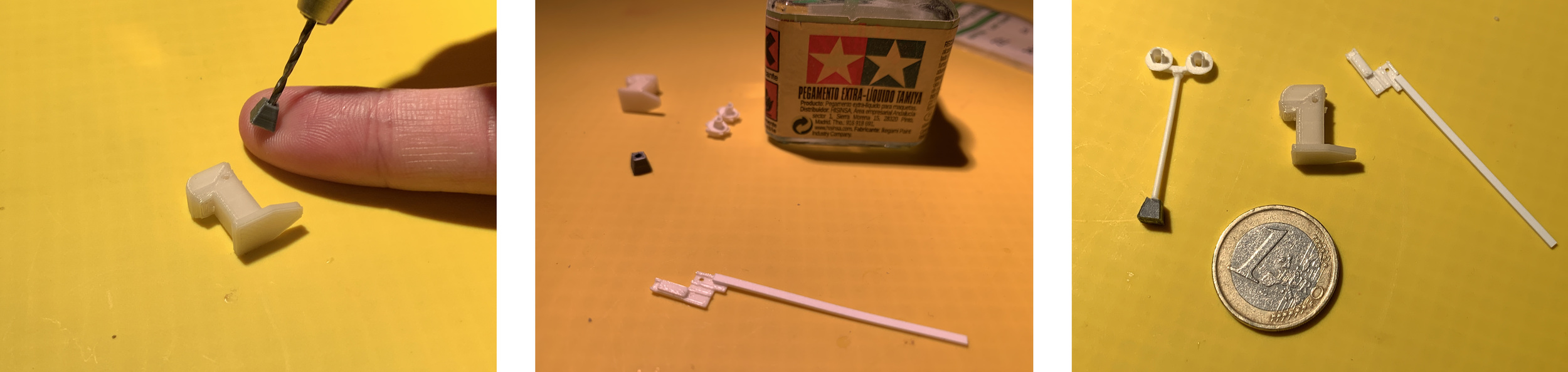
Once the pieces are printed, you have to postprocess them. In my case I remove the supports, but I also use styrene profiles (they are used a lot in modeling, before knowing 3D printing was what I used) for the axis of the barrier, the barrier and the lamppost. I use a small drill to pass the profile through the pieces.
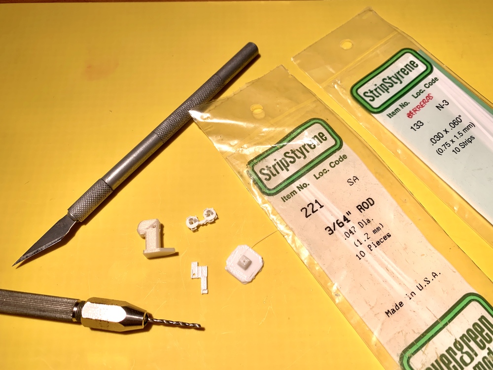
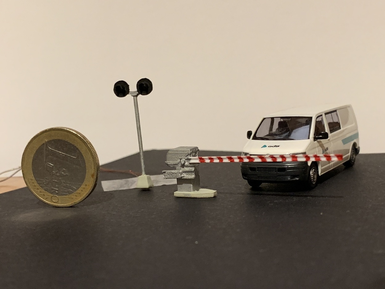
For the bonding process I use SuperGlue and Tamiya liquid glue. The comparison with the 1 euro coin cannot be missing. 🧐
A small video of the movement of the level crossing barriers.
For the lights I will use SMD 1608 LED, they are incredibly small and it costs to weld them. 😣 I reuse the cable that comes inside the headphones because it is varnished and very thin. When I put it in the spotlight, I glue it with SuperGlue and put some baking soda to solidify quickly and have form. In the positive of the LED I pay a resistance of 470 Ohms.
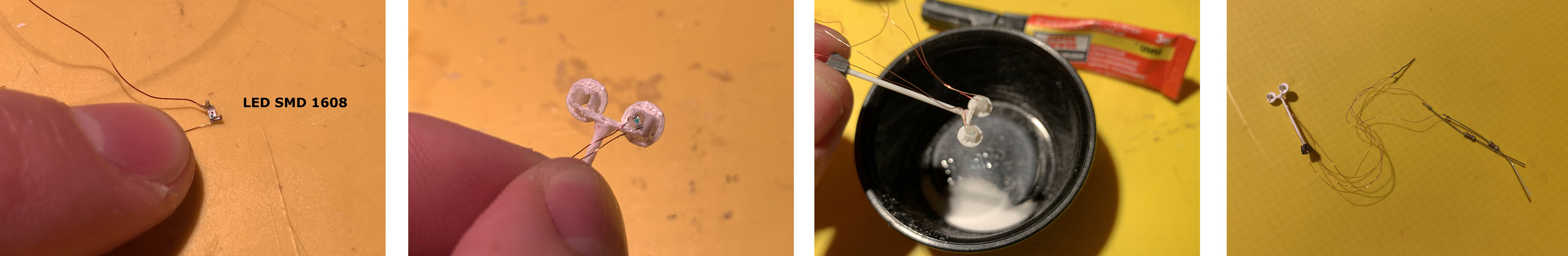
With a little paint and patience 😅, I already have the two barriers and the two lights of the level crossing. Here is an example with a van from my company Adif at 1:87 scale and the euro coin to compare the sizes.
Here is the files to download.
Week 09. Input Devices. Train detection sensor
Phototransistor + Train
I do a little test with the visible light phototransistor, to see how the values behave when the train passes. When it passes over it has very low values between 10 and 0.
VL53LOX + Train
With the time of flight sensor, when it is placed on the track it is out of range, but when the train passes over it gives me values below 40 mm.
Week 10. Applications and Implications
During this week I explain a little more about what my project consists of, the applications, the list of materials. Here I leave the link to the assignment.
Week 11. Output Devices.
The two outputs that I have created this week are very oriented to my final project, the servo and the LEDs. For this I want to test them to see if they work for me.
Hello Servo + Level crossing barriers
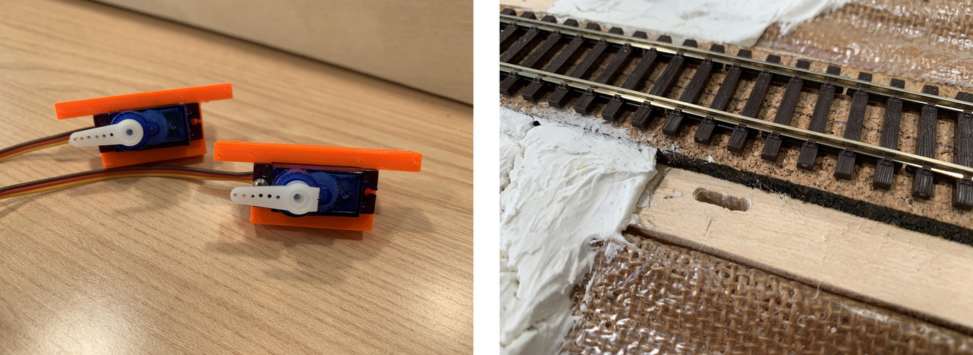
To adapt the servo to the base of the model, I was inspired by fastening the servos from the manufacturer PECO. Since I have the Prusa at home, I make a quick design to attach the servo to the base and have some regulation.
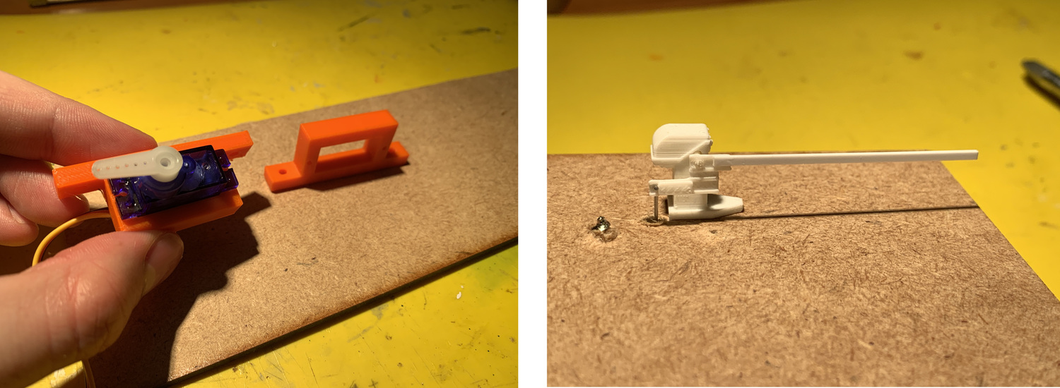
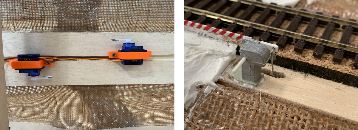
Using a wire, I move the barrier. But I realize that it twists a lot, because it is not making the turn on the axis, in the position that I have placed it it is out of phase. So a quick prototyping and I glue a piece of styrene and re-regulate everything. Now better.
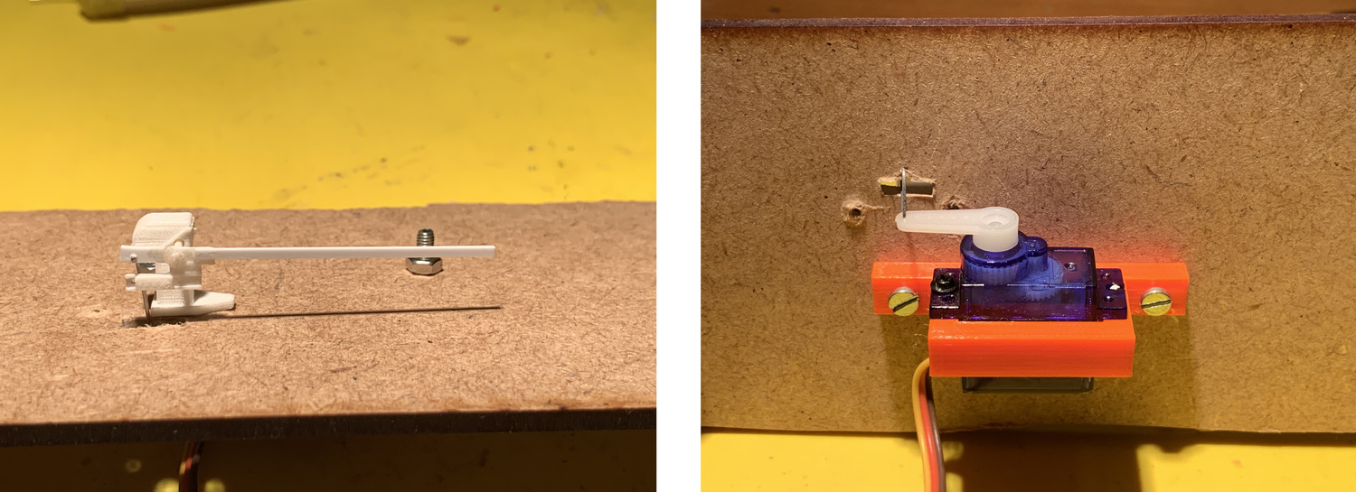
Once everything is adjusted, I load the following Arduino program and that's how it works in the video. Now I have to keep trying different speeds and positions.
Hello LED's + Level crossing signals
When designing this board, place connectors to connect the level crossing signals. The program I use is the same as in this assignment.
Since the signal cables are so thin, I have a piece of rigid cable soldered and resistors to the 470 ohm LEDs. The circuit has 1K resistors, but I keep the resistance at 470 ohms because they are very small LEDs and I still damage them. Here the video of the operation.
Week 13. Invention, Intellectual Property and Business Models.
In this week I explain the invention, the license and the income of my project. In this link you can visit the documentation for this week.
As everything I do is for public use, in my case I particularly want to use a Creative Commons license. In the following link, responding very easily to a questionnaire gives you a result of the license that best suits your project.
I plan to use the following license for my project.

This work is licensed under a Creative Commons Attribution-NonCommercial-ShareAlike 4.0 International License.
I have chosen this type of license because It means that you are free to share it and adapt it or transform it, but under the following terms:
- Attribution: You must give appropriate credit, provide a link to the license, and indicate if changes were made. You may do so in any reasonable manner, but not in any way that suggests the licensor endorses you or your use.
- NonCommercial: You may not use the material for commercial purposes.
- ShareAlike: If you remix, transform, or build upon the material, you must distribute your contributions under the same license as the original.
I also design a slide and record a short video of the project.
Week 14. Networking and Communications
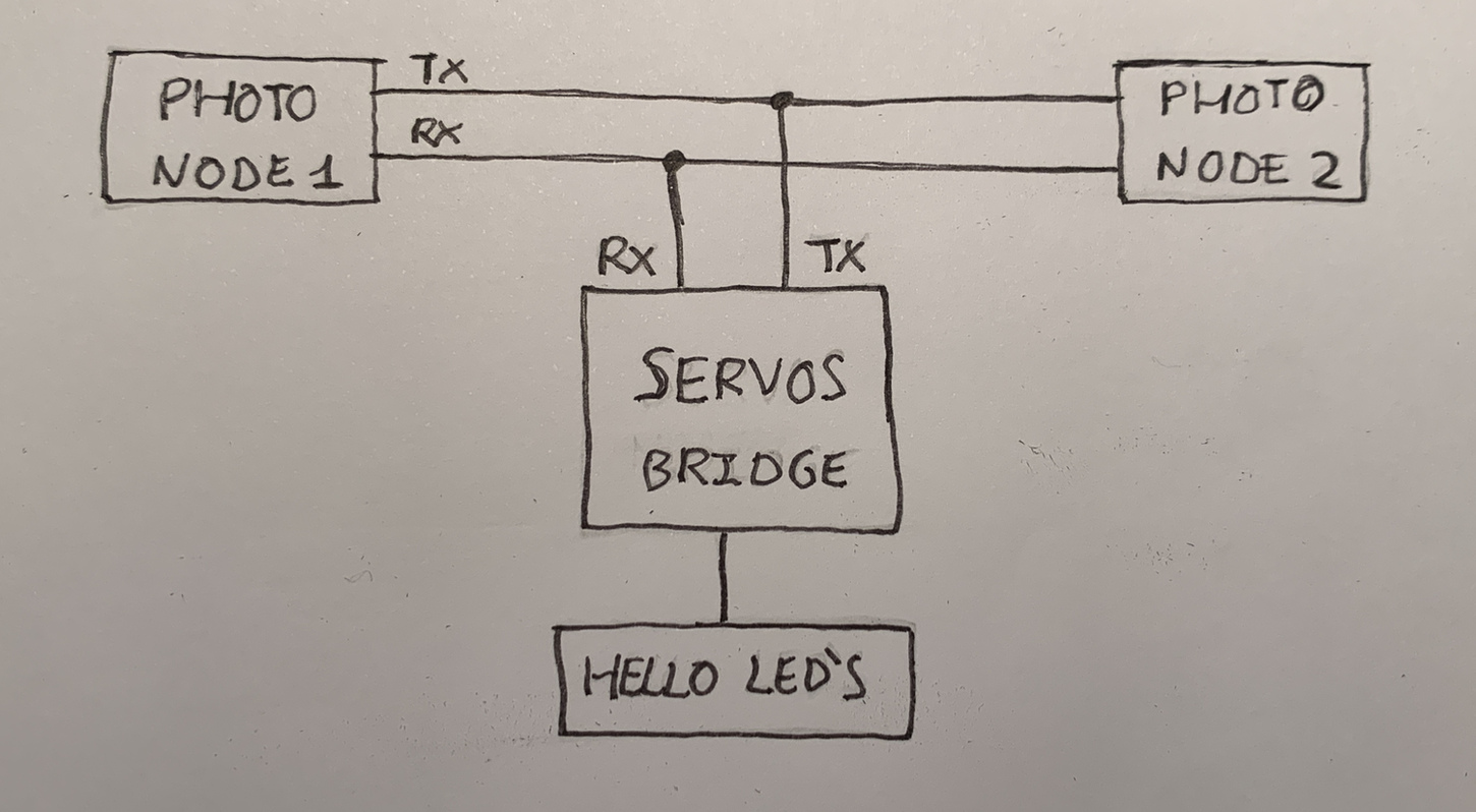
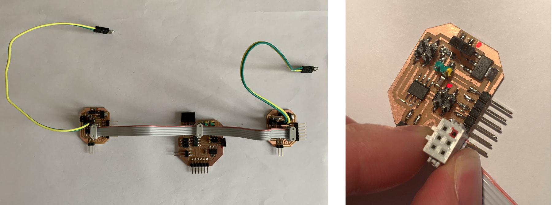
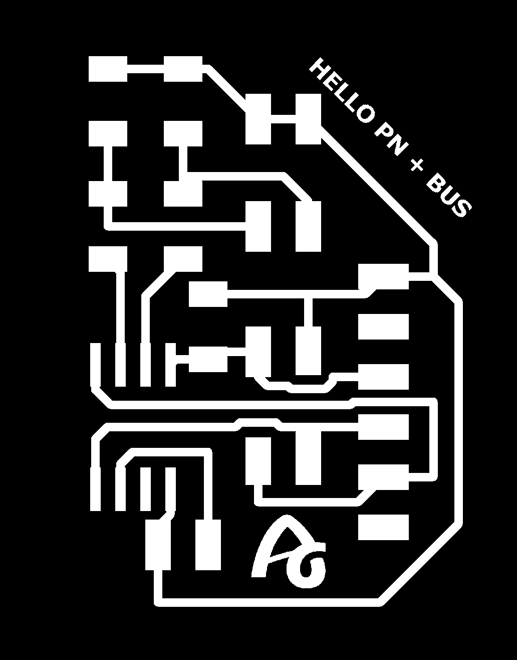
For my final project I am going to try to use networking to communicate through the Serial Bus two nodes (which are two phototransistors) with a brigde (which is the board with the servos for the barriers). This is my scheme.
This would be the connection of the new boards. For more information on the process of creating the new boards, in week 14 I explain it.
Week 16. Wildcard Week
During this week, I used composites to create a piece of my model and see how it looked. If you want to know more, click on the following link. Here is a photo of the final result.
Week 18. Project Development (I)
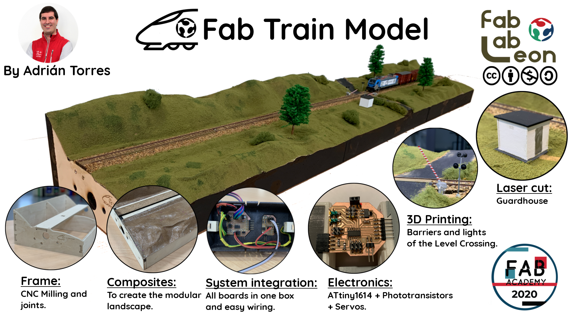
Assembly of the model frame. Prototype 1.
This week I started with the assembly of the structure of the modules that make up the model. In my case there are three modules. I follow the Maquetren regulations. I use 10mm plywood and cut some part with the laser. Speed 5% Power 90% 5000 Hz 400 Dpi.
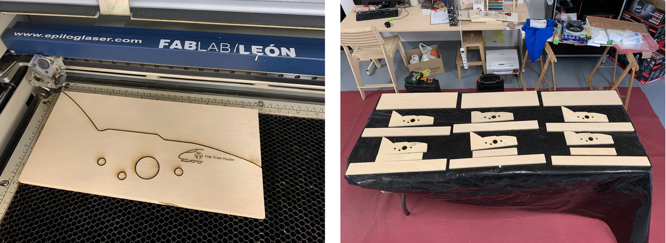
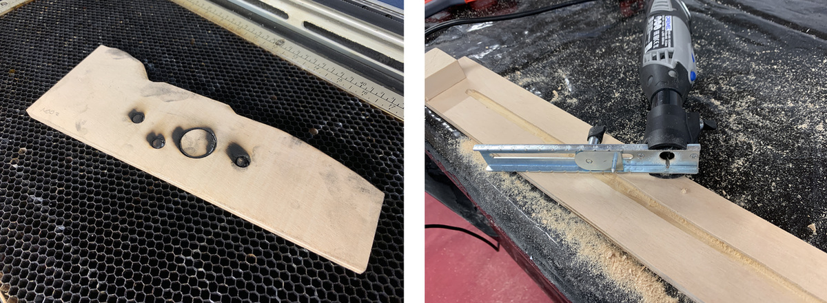
During the cut, deactivate the autofocus thinking that all the boards had the same thickness and it did not. So this board is a little burned. 😬 Before assembling the parts, the track platform milled a channel underneath with the Dremel to route the cables.
Once all the boards are cut, using a 30 x 30 mm bar and screws, join all the pieces to obtain the modules. For this project I am going to need three modules. Being modular, you can build whatever you want.
Composites
Using the designs I created in Computer-Aided Design week with Blender, I extract the STL models from each module. Then with Rhinoceros I make the necessary cuts and slicing to work with the Aspire to mill the polystyrene. Using the CNC and polystyrene I mill the base of the composite as in Wildcard Week.
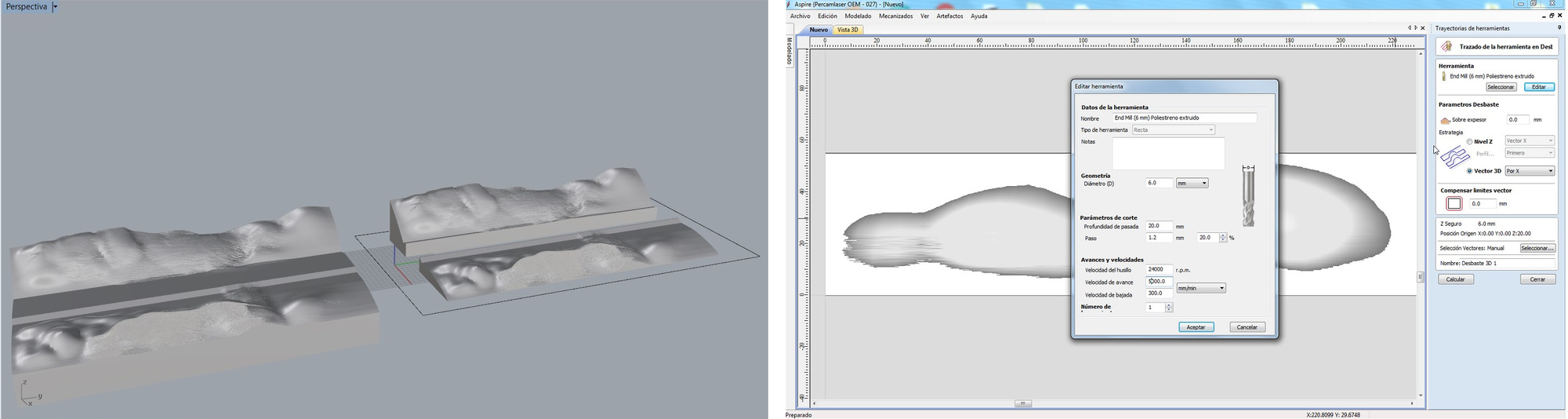
I have uploaded the STL files for all landscapes to Sketchfab because they are too large for my repository. Ideally, each person models their landscape, so we will have different. 🤗
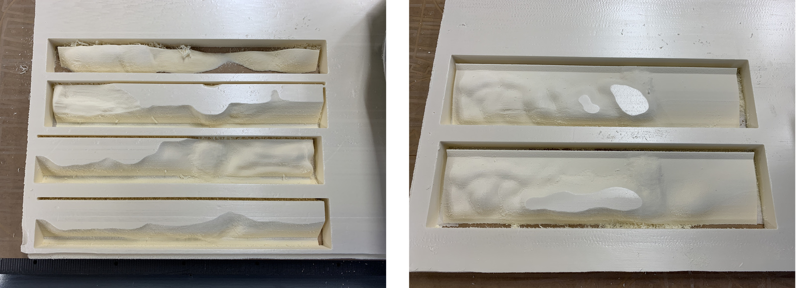
Once all the pieces with polystyrene glue are joined, this is the result.
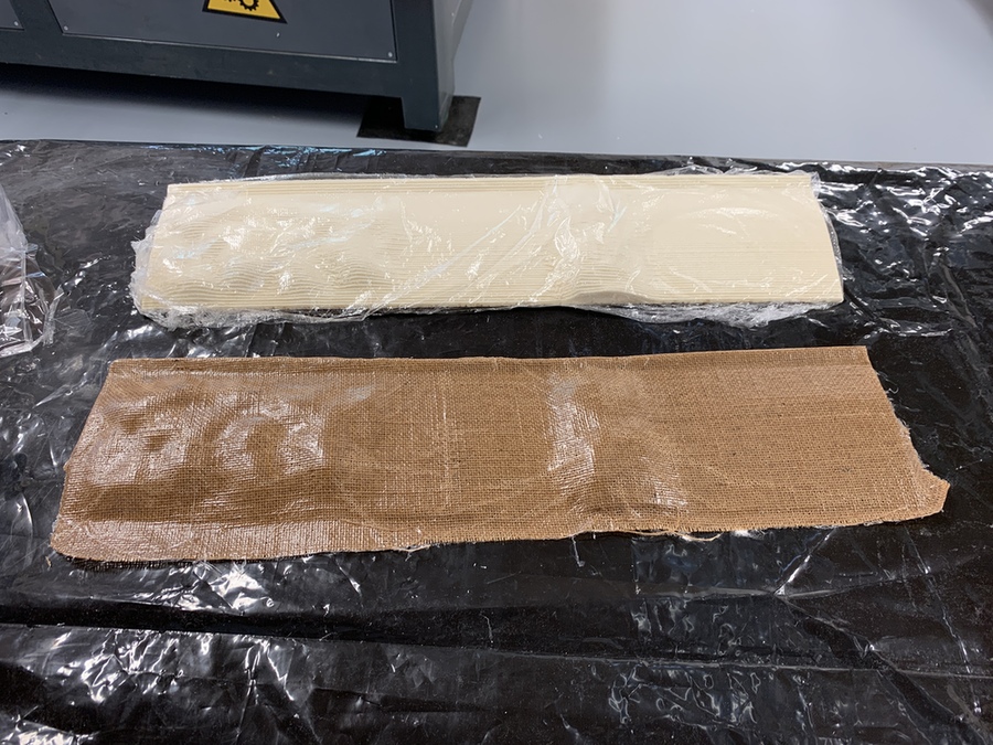
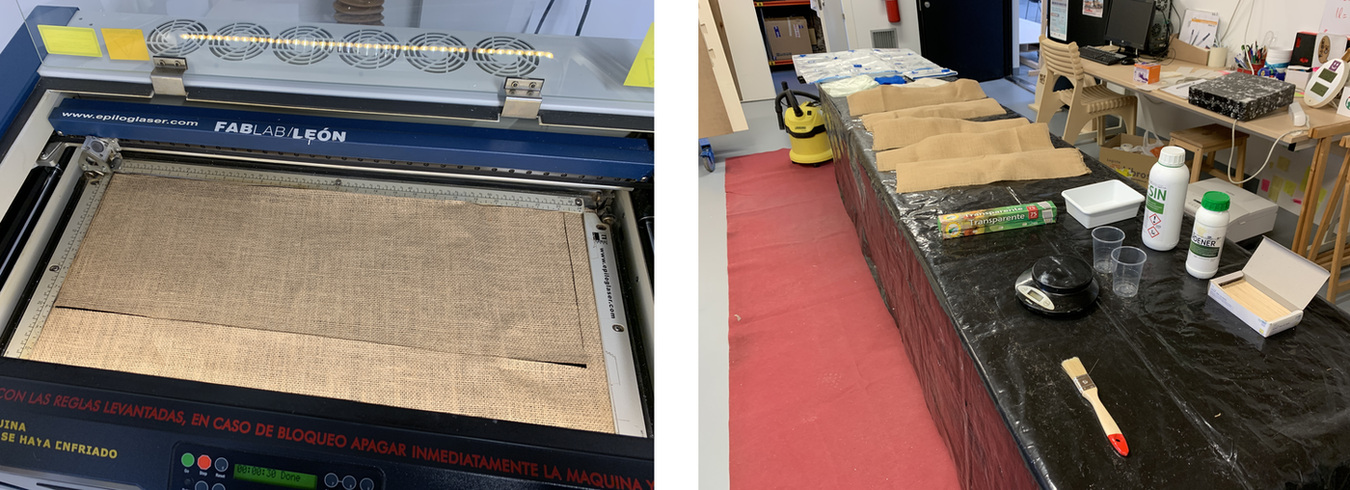
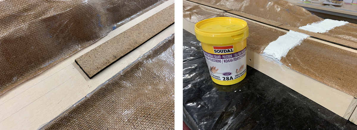
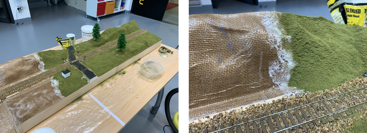
I prepare the burlap with the laser and start the epoxy resin mixing process. Similar to Wildcard Week.
Composite assembly
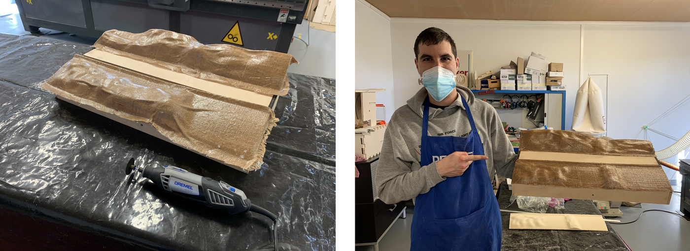
Once the composite has cured, I remove it from the polystyrene mold and adjust it to the module, cutting it with the Dremel. I glue the composite to the model frame with hot silicone. The first module is ready.
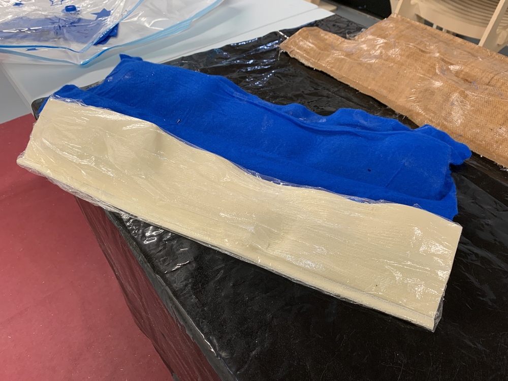
But ... not all composites turned out well. The last one I made forgot to put the release film on it to extract the excess of the epoxy resin and to absorb it by the blanket. So the composite was glued to the blanket (blue blanket). 😰 I have to repeat it (the advantage is that I can use the mold as many times as I need).
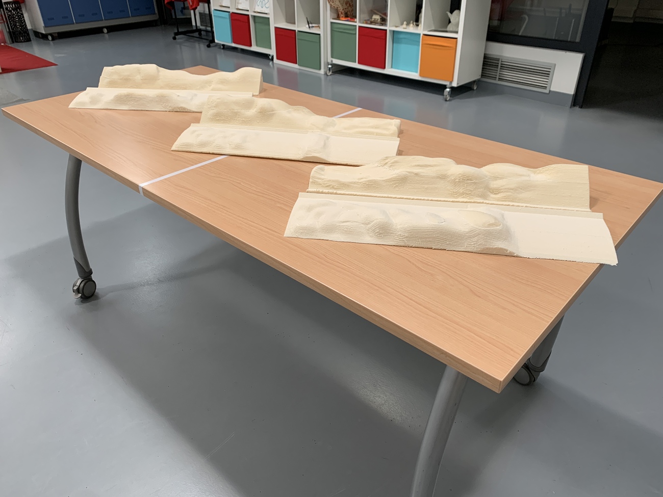
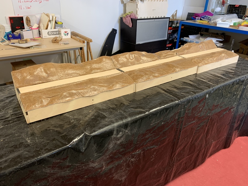
Once all three modules are finished this is the result.
Electronics and System Integration box
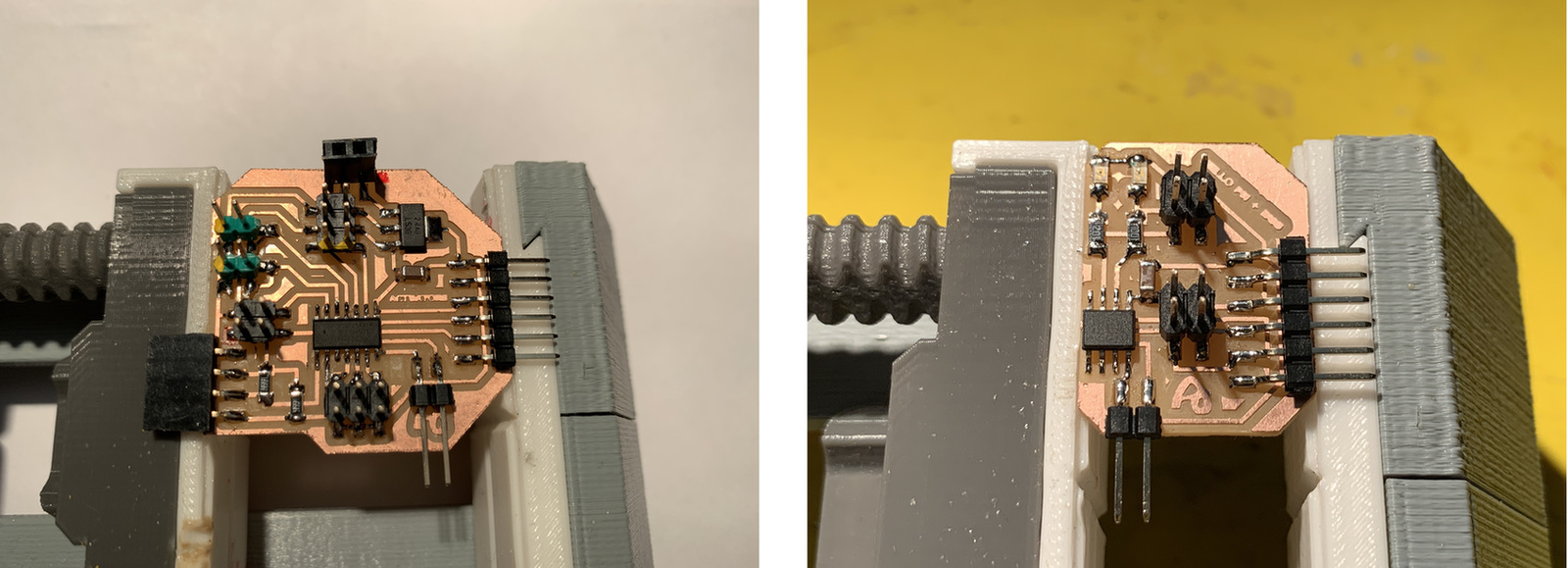
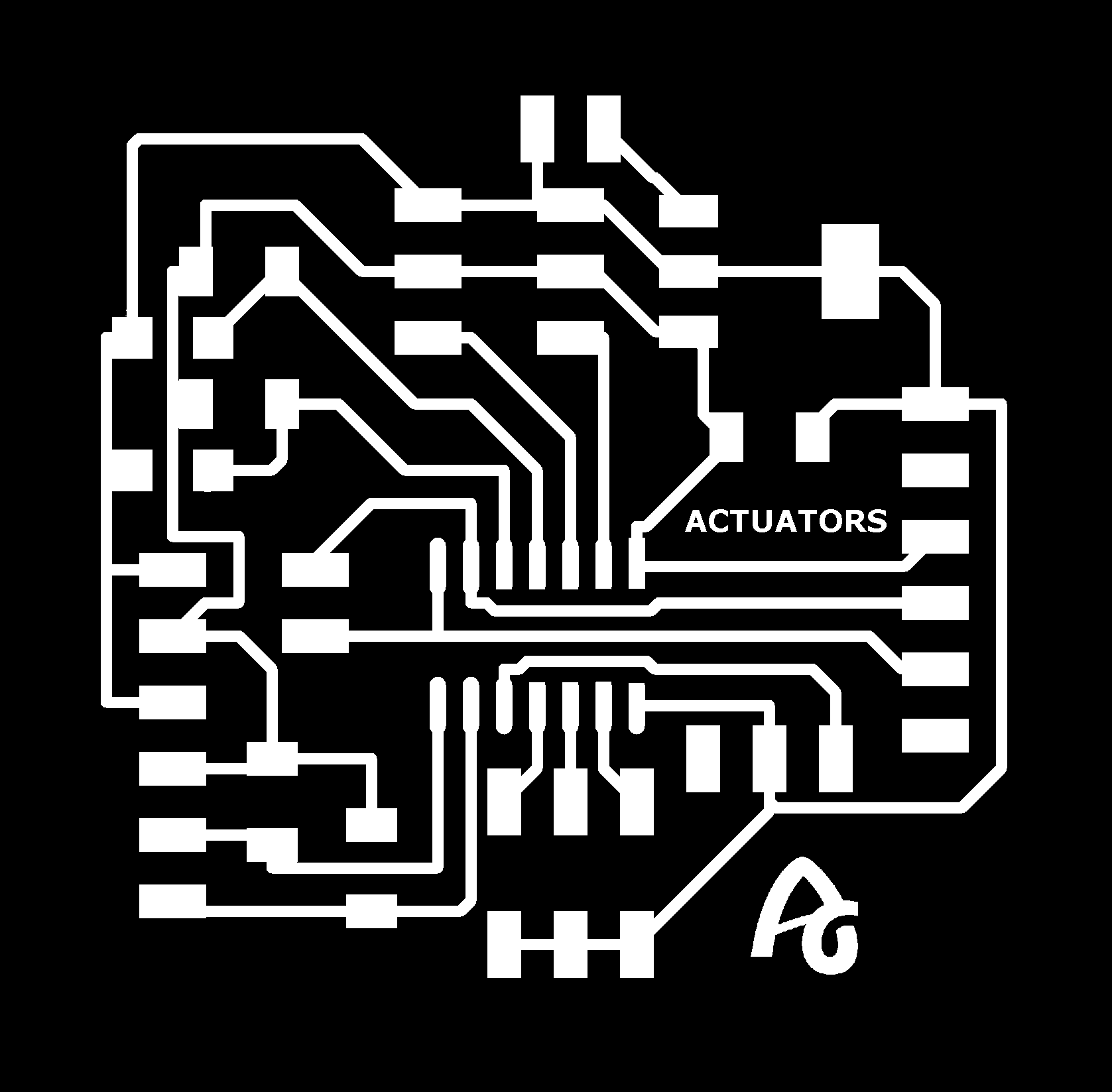
During the week of Output Devices and Networking and Communications I made the boards that I was going to use in my project. The first is an ATtiny1614 that detects the two phototransistors and activates the servos. The second board is an ATtiny412 to control the level crossing lights.
I take advantage of the composite's curing time to design the box that contains the electronics, to achieve system integration. I print the prototype of the box in 3D printing, I have to adjust a hole to place the connectors.
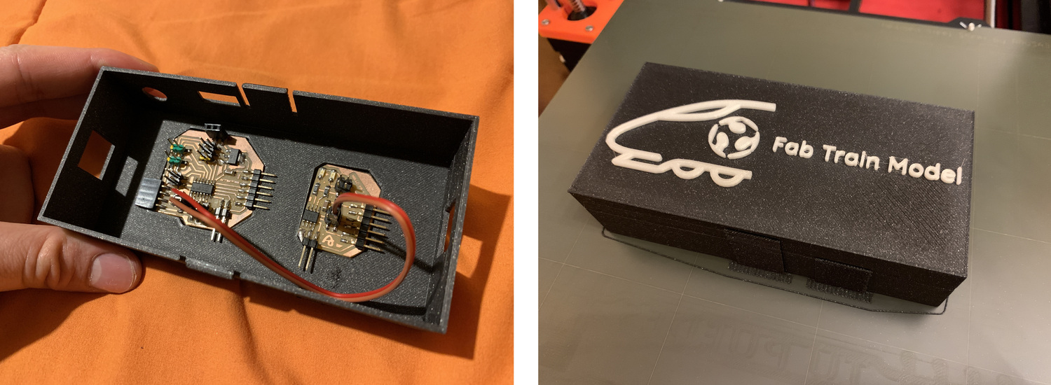
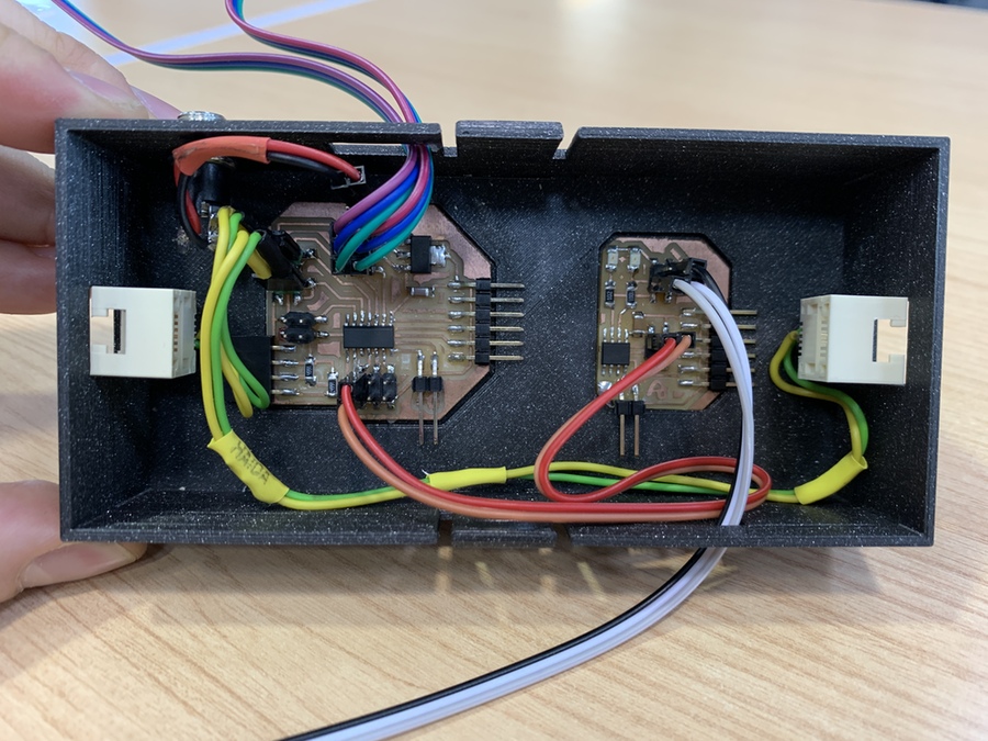
Once I have obtained the connectors (the power one is a normal jack, and I have recycled the RJ11s from old phones) I print a new box and solder the connectors.
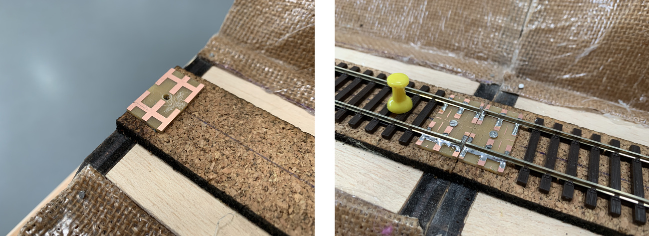
Boards for track and frame preparation.
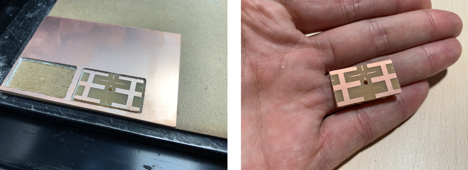
I am advancing homework, for the next steps. To place the track and align it I need a piece of board that can soldered the two rails. For this I create a PNG with Rhinoceros in the shape of the rails and the sleepers. I mill it using the Modela, I increase the offset to remove as much copper as I don't need.
With the laser I cut the cork 5 mm thick (cutting Speed 40% Power 90% 1015 Hz 400 Dpi; offset 3 points from the original focus); the cork serves as a platform for the track and insulator for the noise produced by the passing of the train.
For the road, to smooth it I use polystyrene putty that once dry is very easy to work just by sanding it.
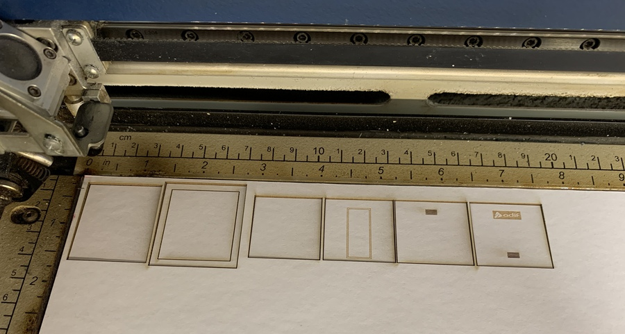
Level crossing booth
Taking advantage of the use of the laser, I cut and recorded the level crossing booth. Later I will assemble and paint it. I use paspartu material and the parameters for engraving are Speed 30% Power 50% 400 Dpi and for cutting Speed 50% Power 50% 531 Hz 400 Dpi.
Week 19. Project Development (II)
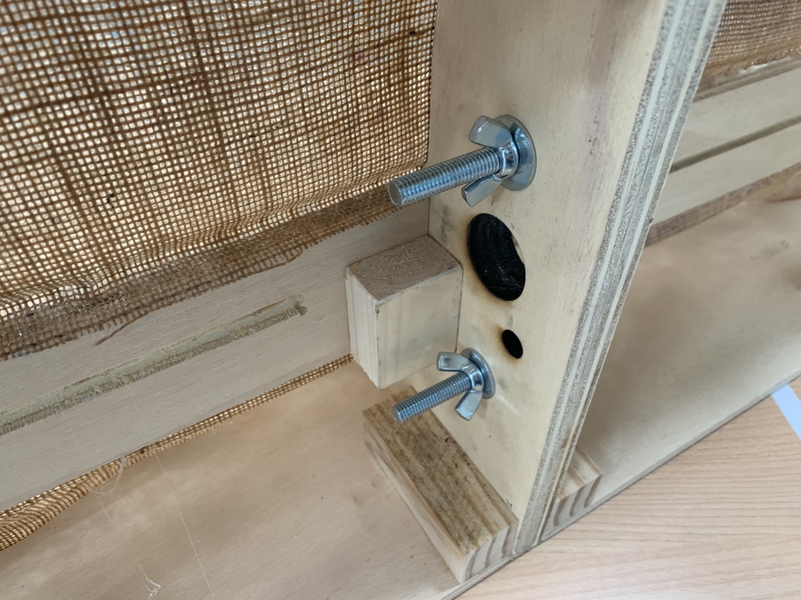
Laying the track.
Once I have all three modules, one with screws and screws. This system is very useful to assemble and disassemble during exposures since you get a very fast adjustment.
The next step is to raise the rails and the sensors. In this prototype I use the Dupont terminals to solder the photransistor. The sensor will go under the track.
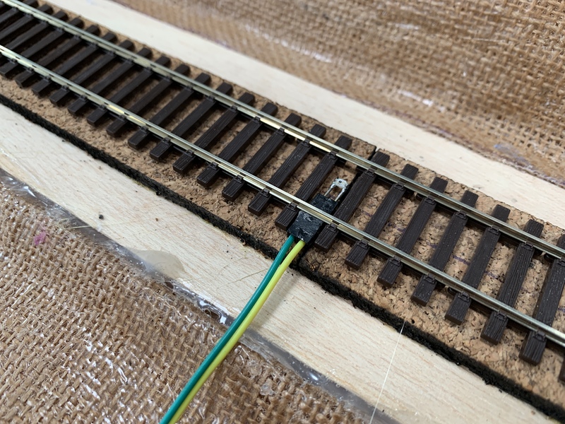
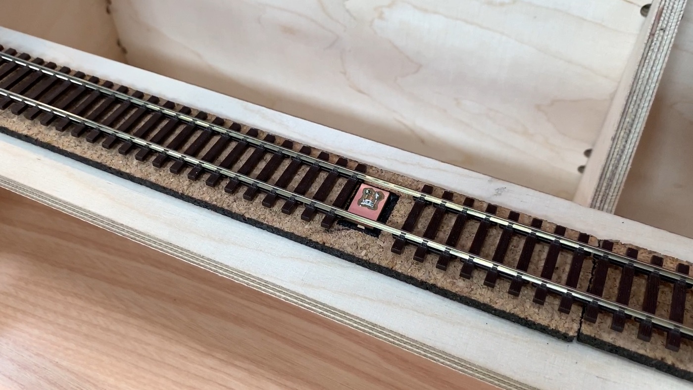
At the ends of the modules, I place the boards I had milled. I glue them with contact glue and I solder them with tin to the rails of the road. Once the glue has dried and the solder has cooled, I secure the board with a nail and cut the rails with the Dremel.
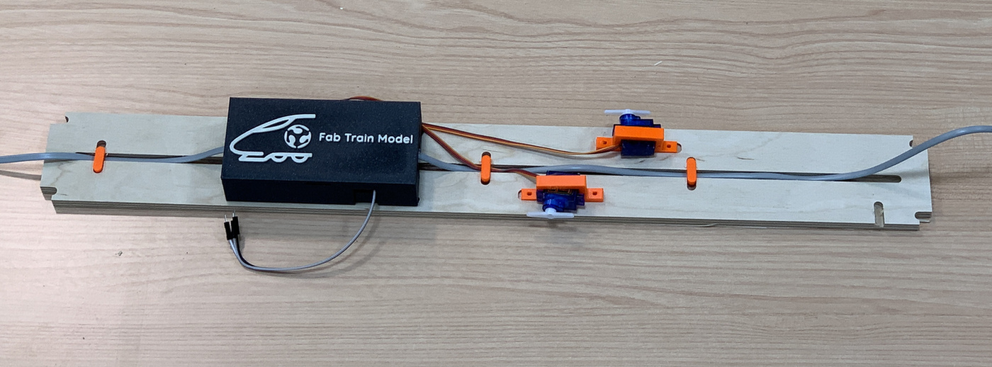
Assembly of servos, barriers, signals and electronics.
Once the railway line has been laid, the next step is to place the level crossing barriers. For this I use the 3D supports that I designed in the week of Output Devices. I also have to make a hole for the barrier movement rod to pass through.
Screwing the servo supports below the track and placing the 3D printed barrier on top. I transmit the movement of the servo and the barrier with a small wire. I take advantage of the channel milled with the Dremel to guide the cables.
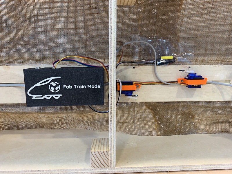
When I already have the servos and signals connected, I fix the box where the boards and all the system integration are. I order the cables thanks to the milled channel.
Second prototype. CNC milled frame.
Thanks to the advice of my instructor Pablo, I decided to CNC mill a wooden frame of the model, using lace and dogbones. Using Rhinoceros design the frame following Maquetren's standards. I have milled it in 9mm thick plywood.
I added the channel for the passage of the cables, a recess for the electronic box and the servos and small slots to hold the cables of the channel. Also, mill another track platform to integrate a support for the phototransistor.
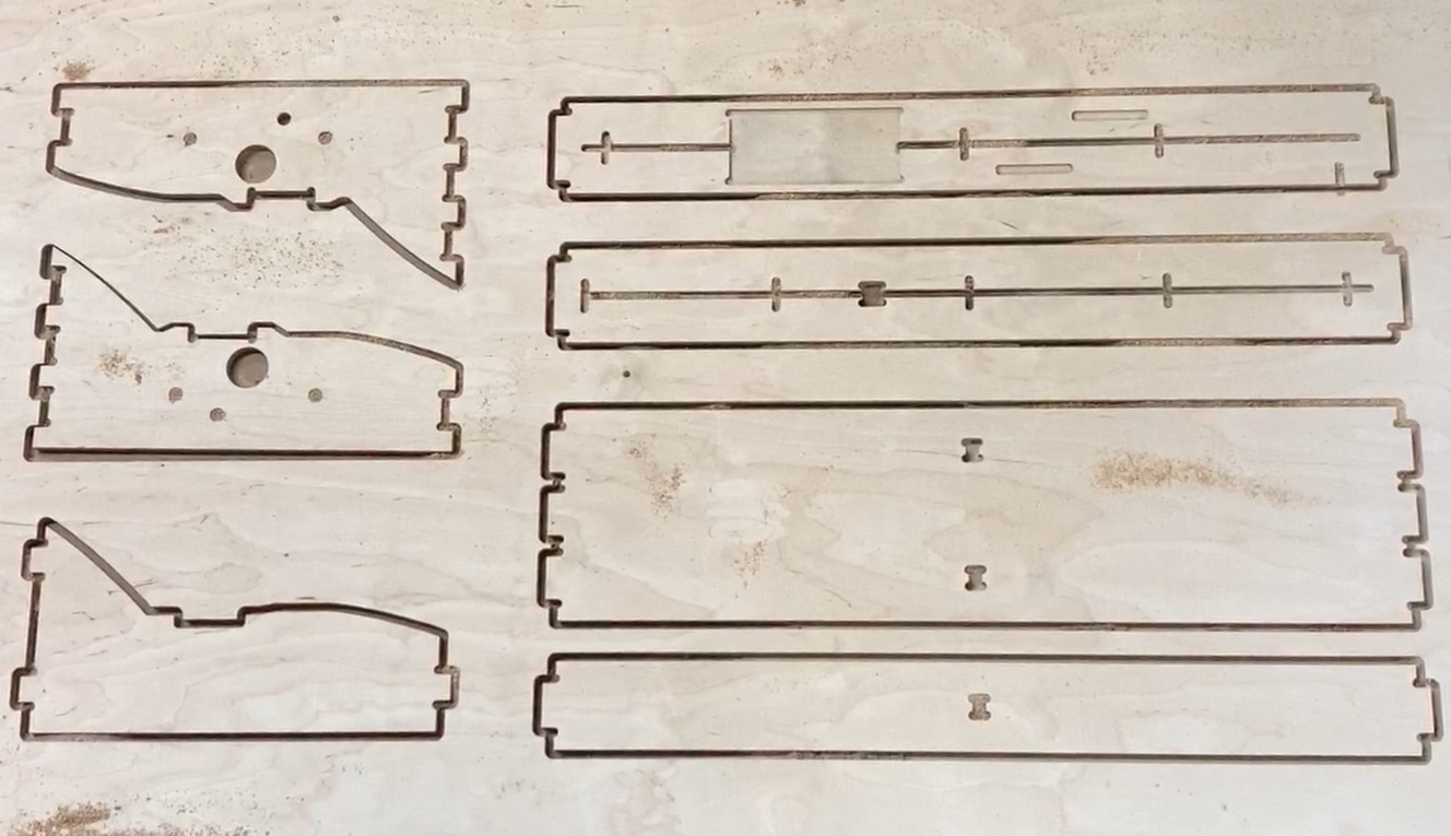
Once the parts are assembled, this is the result of the module.
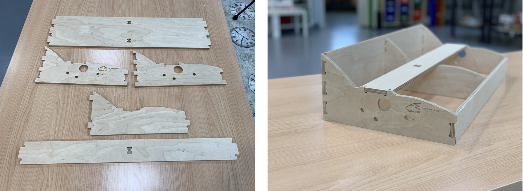
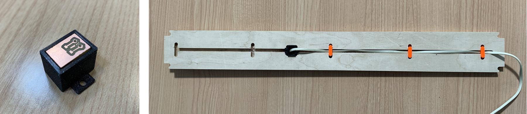
The platform of the road where the level crossing is located, underneath has a recess to locate the system integration box, the supports of the 3D printed servos and by means of 3D printed fittings I can hold the cables.
The platform of the road where the phototransistor is located, has a 3D printed support where it houses a small board where the phototransistor is soldered with two connectors underneath to connect to the cable that goes to the system integration.
Ballast of the track.
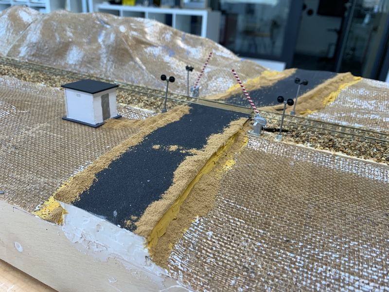
When I have the integrated system in place, I go to the first step of the decoration, the road and the ballast of the track.
For the ballast I use screened river stone. Using various sieves I obtain the desired size. Within modeling you can spend money buying the best materials, but many times you can make a model with natural or nearby products and with them you get great quality.
I place the ballast in the track, then water it with alcohol and then with white glue cut in half with water and a few drops of detergent. The use of alcohol is to break the surface tension, but we cannot get the tail to penetrate between the stones. The detergent drops are in case we need to move the line, simply moistening it with water we can remove the ballast.
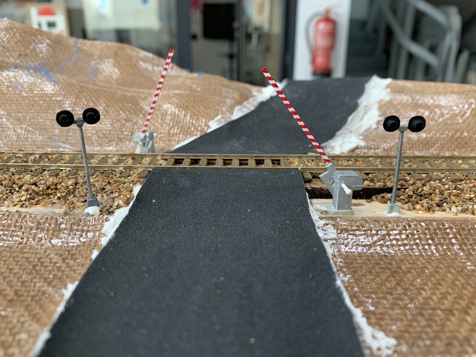
Using very fine grain sandpaper, I create the road. This technique in modeling is very useful because we get a very real asphalt feeling.
As the ballast dries and the road passes to the programming part. Through Arduino and UPDI through the pyupdi I load the two programs to both ATtiny.
Programming
The ATtiny1614 detects the train through the phototransistor, moves the servos and activates an output. When the train goes through the second phototransistor the output is turned off and I move the servos.
//Adrián Torres. Fab Academy 2020
//ATtiny1614
//Fab Lab León

#include SoftwareSerial.h
#include Servo.h
Servo myservo1;  // create servo object to control a servo1
Servo myservo2;  // create servo object to control a servo2
int sensorPin1 = A0;    // analog input pin to hook the sensor to
int sensorPin2 = A1;    // analog input pin to hook the sensor to
int sensorValue1 = 0;  // variable to store the value coming from the sensor1
int sensorValue2 = 0;  // variable to store the value coming from the sensor2
int ledPin1 = 13;//first light
int posinicial = 60;    // initial position of the servos
int posfinal = 30;
int pos = posinicial;
int umbral = 100;  //minimum value of the sensor to activate the system

void setup() {
  Serial.begin(115200);
  myservo1.attach(3);  // attaches the servo on PA4 to the servo object
  myservo2.attach(6);  // attaches the servo on PA5 to the servo object
  pinMode(ledPin1, OUTPUT);
  myservo1.write(posinicial); //initial position of the servo
  myservo2.write(posinicial); //initial position of the servo
}


void loop() {

  sensorValue1 = analogRead(sensorPin1); // read the value from the sensor
  sensorValue1 = map(sensorValue1, 0, 1024, 1024, 0);
  sensorValue2 = analogRead(sensorPin2); // read the value from the sensor
  sensorValue2 = map(sensorValue2, 0, 1024, 1024, 0);

  //values in serial
  Serial.print("pos: ");
  Serial.print(pos);
  Serial.print("Valor 1:");
  Serial.print(sensorValue1);
  Serial.print("  ");
  Serial.print("Valor 2:");
  Serial.println(sensorValue2);
  //Serial.clear();


  if (sensorValue1 <= umbral) { //if the value is less than the threshold
   digitalWrite(ledPin1, HIGH);  //active the lights of the level crossing

   for (pos ; pos >= posfinal; pos -= 2) { //close the barrier
      myservo1.write(pos);
      myservo2.write(pos);
     delay(80);
    }

  }

     if (sensorValue2 <= umbral) { //if the value is less than the threshold
      digitalWrite(ledPin1, LOW);   //turn off the lights of the level crssing
      for (pos; pos <= posinicial; pos += 2) {   //open the barrier
      myservo1.write(pos);
      myservo2.write(pos);
      delay(80);
      }
    }

}
I use an ATtiny412 to control the flickering of the level crossing lights through the activated output of the ATtiny1614.
//Adrián Torres. Fab Academy 2020
//ATtiny412
//Fab Lab León

int ledPin1 = 0; //led1
int ledPin2 =1; //led2

void setup() {
  pinMode(ledPin1, OUTPUT);
  pinMode(ledPin2, OUTPUT);
}

void loop() {
     digitalWrite(ledPin1, HIGH);
     digitalWrite(ledPin2, LOW);
     delay(750);
     digitalWrite(ledPin1, LOW);
     digitalWrite(ledPin2, HIGH);
     delay(750);
}
In the following video you can see the operation of the barriers and the signals when I cover the phototransistors. The servos vibrate a bit in the down position. Create an issue, and one of the recommendations Neil told me to do is check the board's power or the PWM. In the end it was a power supply problem.
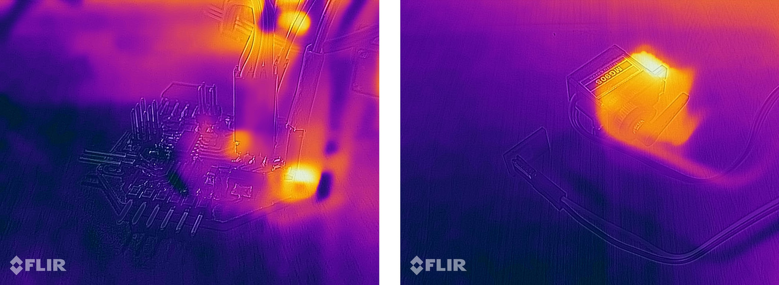
Using a CAT S61 smartphone equipped with a thermal imager, I try to see how the hot spots are observed on the main board and on the servos. The image of the servo board is a little out of phase with the heat point, because the manufacturer says that in small objects it has a certain lag. The actual point of heat is the voltage regulator.
Decoration
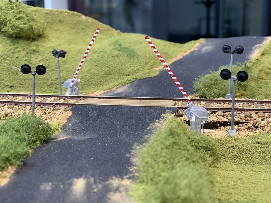
Once everything is verified, the last step is to finish the decoration. For this, the first thing I do is paste the level crossing booth that I cut and engrave with the laser and paint the rails in rust color. I also put some screened dirt along the road.
To put the vegetation I use white glue and Woodland Scenics brand herbal and foliage products. The advantage of having the earth-colored composite is that apart from giving it texture, if there is any place of grass missing, there seems to be dirt.
After a couple of hours and patience, this is the result of putting some vegetation. The model stands out a lot. I have put several trees and several bushes. Also laser cut a board for cars to pass through the level crossing.
Here is a video of the placement of the vegetation and the decoration of the model.
A little black paint for the frame and some cleaning, and the model is ready.
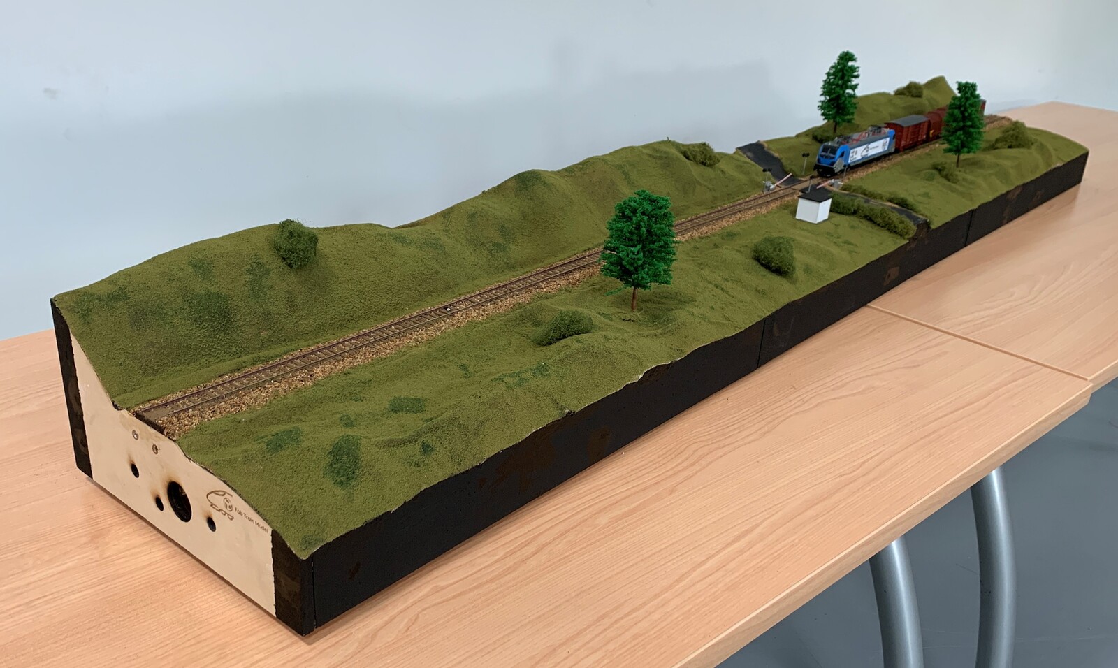
As a detail for the presentation, put two small characters, Neil and me, who are talking about the project and the Fab Academy. 😅
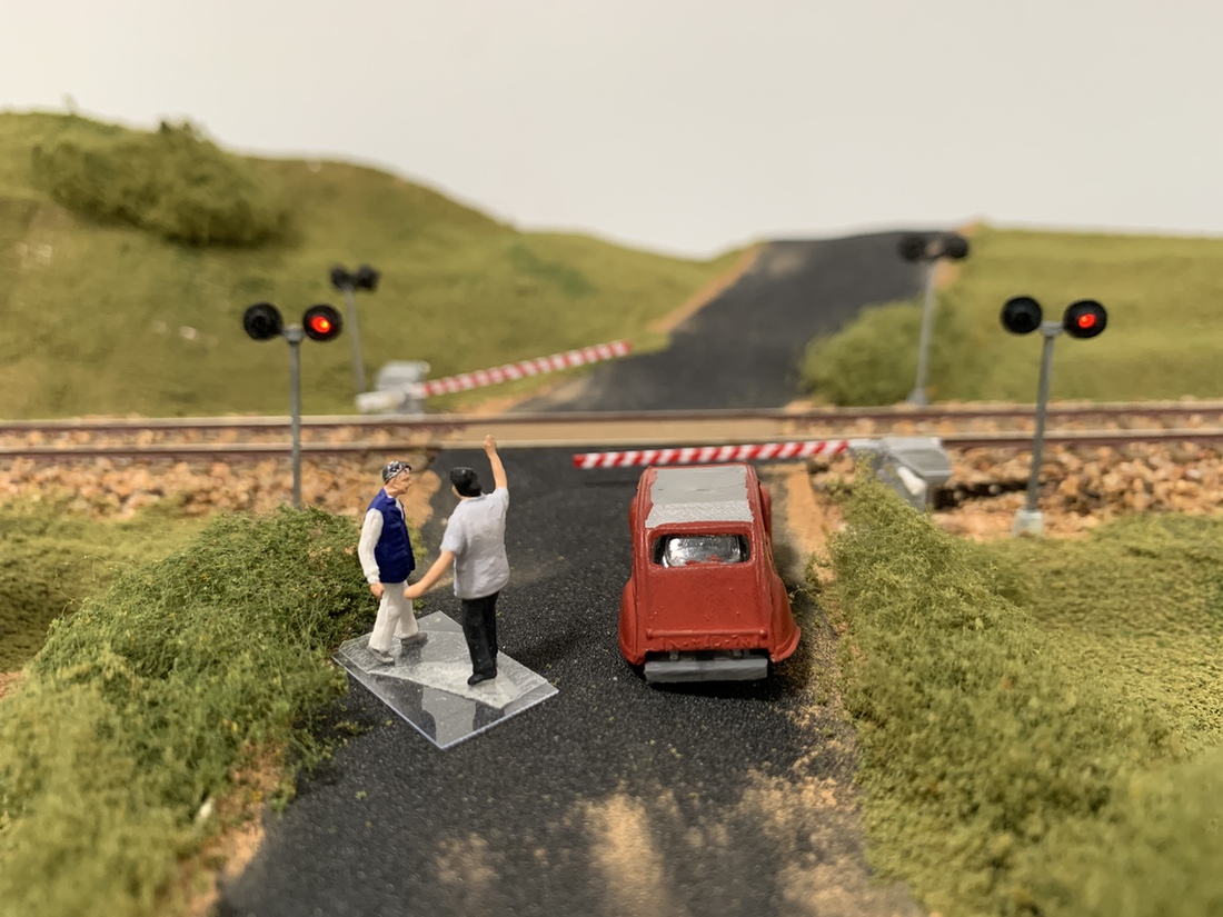
And this is the result of the project, running the trains and the level crossing working. 🤗 🚂🚂🚂
Files
Find below the files that I made for this final project.
CNC- CNC Frame
- Composite. Module 1 part 1-1 (SketchFab)
- Composite. Module 1 part 1-2 (SketchFab)
- Composite. Module 1 part 2-1 (SketchFab)
- Composite. Module 1 part 2-2 (SketchFab)
- Composite. Module 2 part 1-1 (SketchFab)
- Composite. Module 2 part 1-2 (SketchFab)
- Composite. Module 2 part 2 (SketchFab)
- Composite. Module 3 part 1-1 (SketchFab)
- Composite. Module 3 part 1-2 (SketchFab)
- Composite. Module 3 part 2-1 (SketchFab)
- Composite. Module 3 part 2-2 (SketchFab)
- Composite. Module 3 part 2-3 (SketchFab)
- Motor of the level crossing
- Base
- Lamppost
- Support of the barrier
- Support 3D servo
- Support 3D Phototransistor
- System Integration Box
- Cable support 3D