Computer-Controlled Machining
This week I learned about computer-controlled machining. This included:
Unit Description
Group assignment:
- Complete your lab’s safety training
- Test runout, alignment, fixturing, speeds, feeds, materials and toolpaths for your machine
- Document your work to the group work page and reflect on your individual page what you learned
Individual assignments:
- Make (design+mill+assemble) something big
Learning outcomes
- Demonstrate 2D design development for CNC production
- Describe workflows for CNC production
Checklist
Linked to the group assignment page:
-
Linked to the group assignment page:
-
There are two types of assignments, two group and one individual, since I am alone in my personal Fab Lab I will do both. All of my work will be documented here, so there won’t be a group assignment page.
Complete your lab’s safety training - I reviewed the saftey training I had with the National Coalition of Certification Centers (NC3) for Fundamentals of Robotics that covers:
- Types and Sources of Robotics Hazards
- Robot Safety Requirements
- Robot Safeguards
- Safety Standards
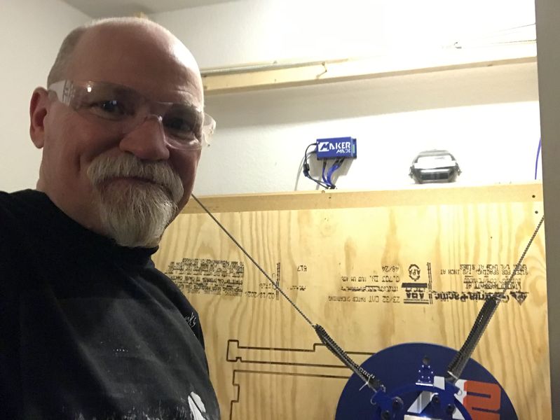
In my personal Fab Lab I have safety glasses to protect my vision.
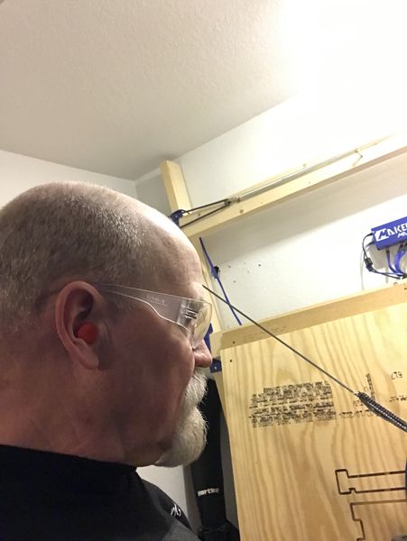
And earplugs to protect my hearing.
As a safety precaution, I have a power strip with a red light in the power button as a E-Stop. Both the controller and router are powered from the same power strip, so I have one button to deenergize the system in an emergency. Additionally, I do not leave the area when the CNC machine is operating and continuously monitor the screen and the tool progress throughout the milling process.
Test runout, alignment, fixturing, speeds, feeds, materials and toolpaths for your machine:

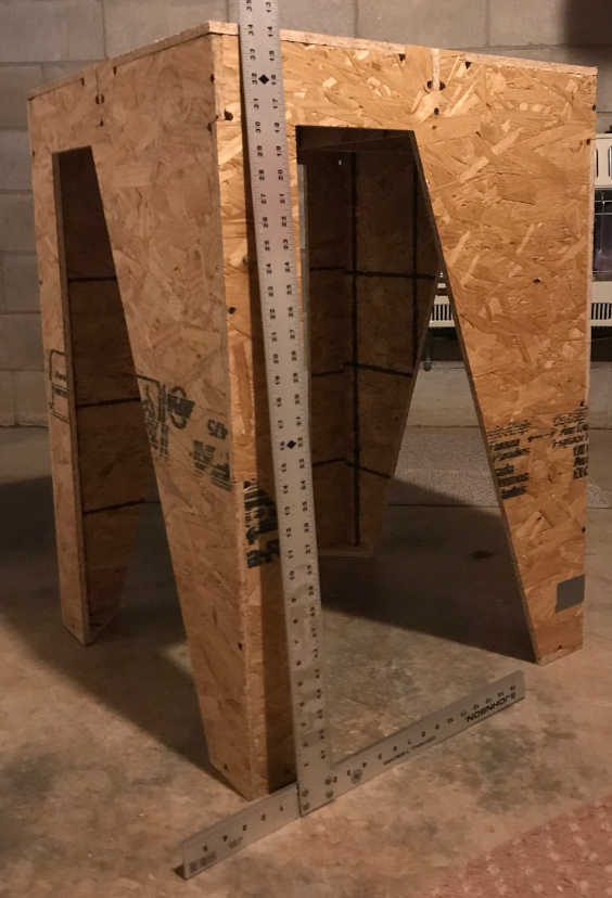
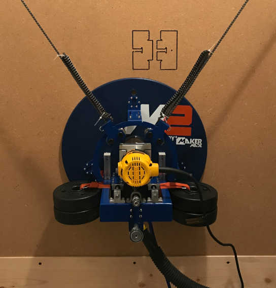
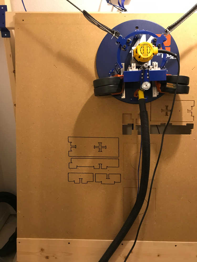
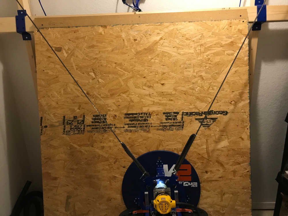
- My personal Fab Lab has the MakerMade M2 CNC milling machine. I was required to make the frame system by following the frame assembly guide provided by the vendor; I chose the Mini Frame for a 4x4ft cutting area, so it would fit in my closet in the basement. I do plan to make the Standard Frame for a 4x8ft cutting area when I have room for it. Then I had to assemble all of the parts shown on the vendor website including the electronics for CNC control.
| SPECIFICATIONS | |
|---|---|
| Cutting Volume | 4ft x 8ft x 3.8in (1.22m x 2.44m x 9.65cm), up to 32 sq ft |
| Frame Size | 10ft(width) x 8ft(height) x 3ft(depth)(3.05m x 2.4m x 91cm) |
| Frame Material | 2x4 wood, 4 - 24in x 48in x 5/8in MDF, metal fixtures |
| Maximum Cutting Speed | Up to 40 in/min (ipm) (17mm/s) |
| Spindle | DeWalt DWP611, 120V; 1.25HP Variable Speed Control 16K-27K RPM |
| Software | Gcode Sender: Makerverse |
| Control power | Power: 100-240v 50-60Hz 2.0A Input;12v, 5A Output |
| X,Y, and Z motors | Industrial Drive Motors |
| Endmills | 1/8in-1/2in (Depending on router used) |
| Control System | Arduino: Arduino DUE v1.2 Control Shield |
| Firmware | GBRL 1.1g |
| Connectivity | microUSB |
-
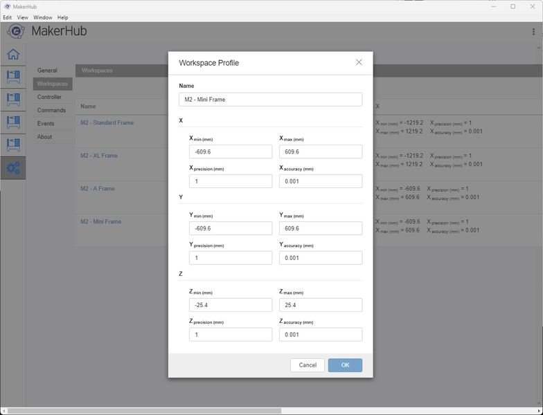
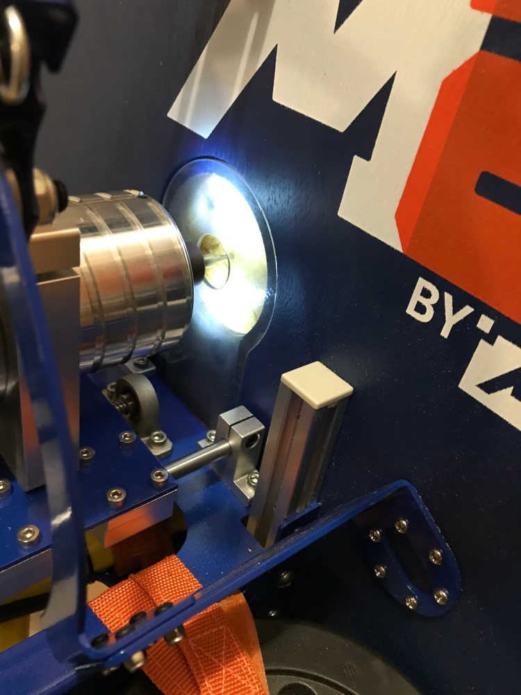
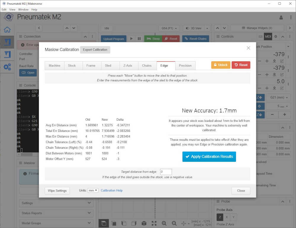
After construction, I was required to calibrate the system using the Makerverse software; The M2 Calibration Guide took me through this process to check the alignment of the frame. The software allows entering compensation settings to make up for any slight misalignments. After I began using Makerverse, the name of the software was changed to Makerhub, but it is downloaded from the same link above. Additionally, the Arduino IDE is also available at the same link since it is required to communicate with the Arduino DUE v1.2 Control Shield. Since my computer crashed I had to reload the software, so this was a good place to return to for the link.
-
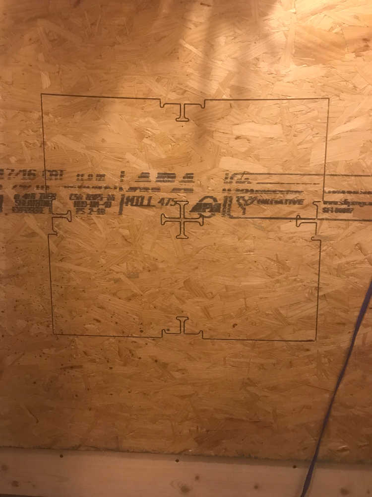
This image shows the precision and accuracy of the XY, and Z axis. Although this seems very accurate, and the vendor states, “Many users have been able to achieve an accuracy within 1mm with the M2!” The accuracy cited on this website is not more than a 1/8” variance across 32 square feet. The tolerances acheived by such accuracy should result in very tight fits for joinery. However, I am still learning and have not achieved satisfying results each time. I attribute this to my lower level of experience and hope to improve over time.
-
I learned more about Differences Between Accuracy, Error, Tolerance, and Uncertainty in a Calibration Results and that “Tolerance = difference between upper and lower tolerance limits” and that “It is the maximum error or deviation that is allowed or accepted in the design of the user for its manufactured product or components.” I also found the publications referenced by the author here. I accept the results that I have obtained, but I think I can improve them with practice.
-
Sheetrock screws for fixturing as well as Raptor nails and staples.
-
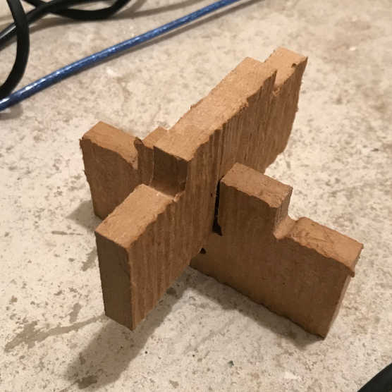
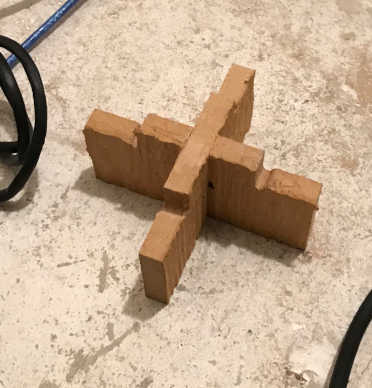
Runout was tested by cutting a test part and assembling it. The fit was very tight and required a hammer to put the parts together.
-
The Easel Inventables software allows the selection of materials and endmills as well as the feeds and speeds. However I did review the Machinery’s Handbook to ensure that I could make the calculations if necessary. Inventables provides a page for Calculating Your Cut Settings: Basic Feeds and Speeds Information. They teach about the following:
| What are cut settings (feeds and speeds)? | |
|---|---|
| Feed Rate | Feed rate is the rate at which your machine advances along carve your project. |
| Depth Per Pass | Depth per pass is how deeply the tool goes into your material every time it starts a new toolpath. |
| Spindle Speed | Spindle speed is the rotational speed of your tool, measured in revolutions per minute (RPM). |
| Chip Load | Chip load is the amount of material removed by each flute (or tooth) on the bit. |
| Vendor Recommendation | DeWalt DWP611, set between 1 and 2 or 16K-18K RPM. |
-
The Easel Pro Software allows you to select tools and add new tools if they are not in the database. I always try to select a tool that is in the database, so the proper feeds and speeds are set for me. If I don’t have the exact tool of the database, I improvise and choose a more conservative feed and speed.
-
The toolpaths are generated by the Easel Inventables software and saved as g-code; the g-code contains the feed and depth per pass, but the speed is determined manually by the dial setting on the router. The g-code is sent to the CNC mill using the Makerverse software.
This is the test part designed in SketchUp with the guidance of Make: Design for CNC book:
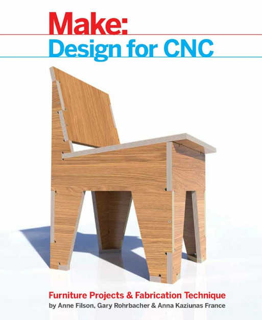
I used the AtFAB_Test Pieces for the Table provided by the authors. The test pieces are a section cut out of the table, complete with joints and sniglets. The authors say, “Using a sniglet fillet pulls the tool deep into the inside angle, resulting in flush-fitting joinery.” Sniglets are similar to dogbones and they allow the joint surfaces to be tight and perpendicular on each face. Since the endmill is round and rotating, the circular sniglet compensates for this while ensuring maximum face contact. ProtoLabs Network says, “when a part with a rectangular shape needs to fit in a cavity, add undercuts to the corners of the cavity.”
To get to the point of using the test pieces, I had to isolate, rotate, and orient the parts so they could be imported into Fusion 360 as a DXF file. I also discovered that they need to be edited in to 2D faces and then exported as 3D objects in DXF format to Insert them into Fusion 360 properly. Once inserted into Fusion 360, they are extruded into 3D models. Then they are scaled depending on the material thickness.
The table test part was designed for a material thickness of 19mm (TNOM) and the maximumum thickness of the MDF material was 1/2 inch; this resulted in a Scaling percentage of 0.668 This is a considerable amount and would drastically change the dimensions of the final part. However, I just wanted to mill something now that my machine was calibrated :)
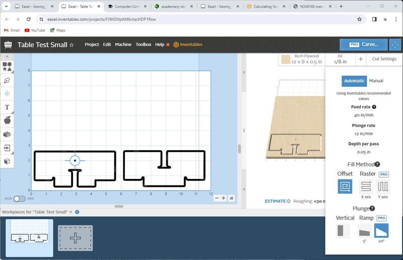
The above test part was made in the Fab Academy 2022 cycle, but I did not complete the whole test part due to my only endmill breaking. This is the settings in Easel Pro for the above test parts. I chose the 1/8” endmill for two reasons: the size of the fastener hole was 1/8” and I had an inexpensive endmill with a 1/4” shank that I was willing to risk. Additionally, The Easel Pro software had the same endmill in the database that provided the proper feed rate, plunge rate and the depth per pass as shown below. In the next spiral I will have more endmills and experiment with the feeds, speeds and materials. I will put a note below on my table construction about the endmills I used.
Also note in the below image that the part on the left has a bullseye to show where the hole will be. To make that a drill hole, I replaced the 3D design hole with the built-in drill hole placement within the Easel Pro software. It is a tedious process, but the end result is a hole of the correct size in the correct place :)
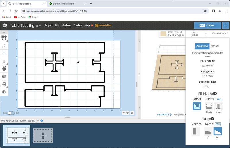
This is the remainder of the test part in Easel Pro and the settings were the same.
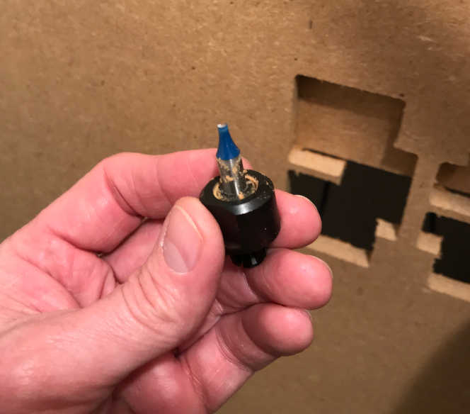
This is after I stopped the machine since I noticed it wasn’t cutting anymore. The endmill seemed to ride up on the material in the lower right corner. Although it finished that part, the endmill broke before it finished the other part. The strange movement must have weakened the tool.
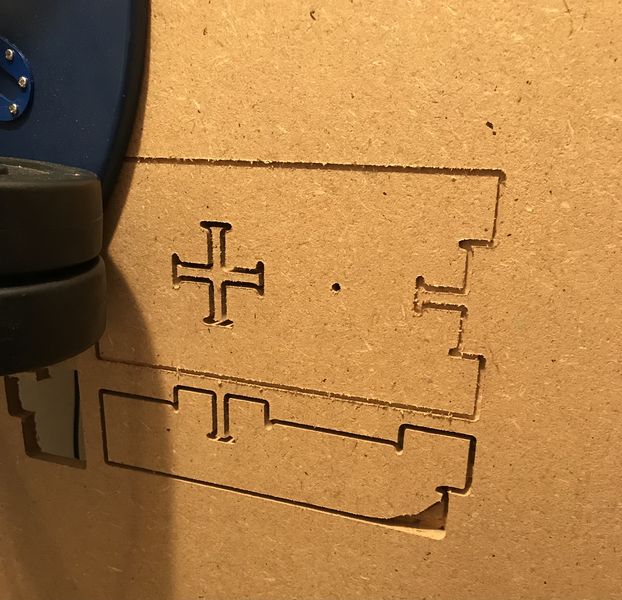
This is the broken endmill. I never found the broken piece.
I had to move on and was not able to revisit this assignment until the Fab Academy 2023 cycle.
Documented how you designed your object (something big):
- Documented how you designed your object (something big):
The design process had several spirals, but this is a good place to start.
Thinking about revisiting the chair I prototyped in cardboard and 1/8” plywood, but decided a parametric designed table would be a safer route.
The workflow to get the parametric design into a g-code format: Use Processing 3 program to design the table and output as a DXF file.

To do that, navigate to the folder containing processing.exe and run it; get past the welcome screen, click File > Open > AtFAB_TBL_170731.pde (provided by the authors of Make: Design for CNC); this will open the processing code:
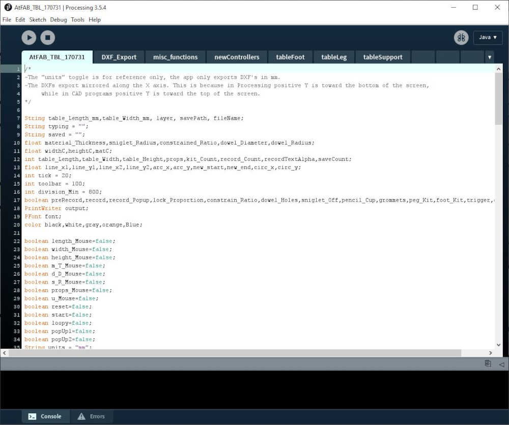
…feel free to browse the magic; only code, no graphics. This software is there for me and you to imagine and make something we don’t have the skills to do. It’s what we have waited for! So, here we go. Just push play :) This is what you get:
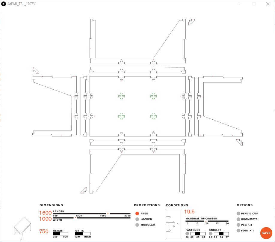
Make adjustments to your satisfaction. I want a table for my bandsaw, so I choose 24”x 24”; oh, you’ll have to select inch for units. I want a tall one to “make something big” and big enough for a bandsaw platform. I am using OSB, so it’s just under 0.5”. I want it tight, so 0.47” should work ;) Here it is:
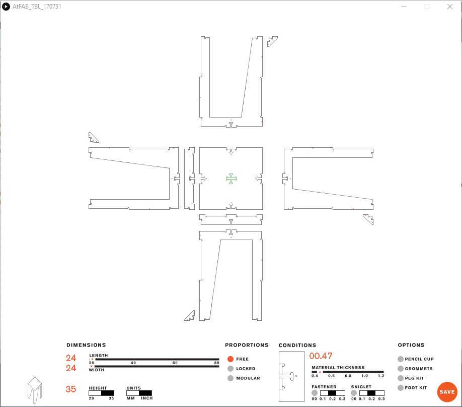
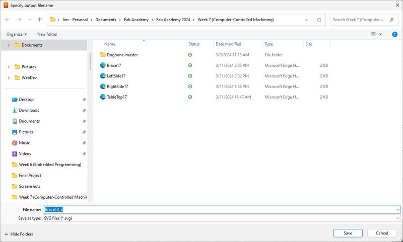
Click save, add the file name, and press Enter. It will save to the location of the original source folder as a DXF file; in my case 24x24x35bandsawtable.dxf.
Now import it into Fusion 360:
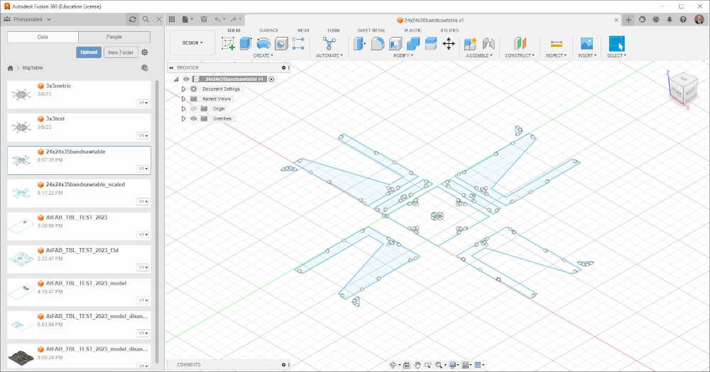
I had to scale it to meet the material requirements, so let’s see how I did:
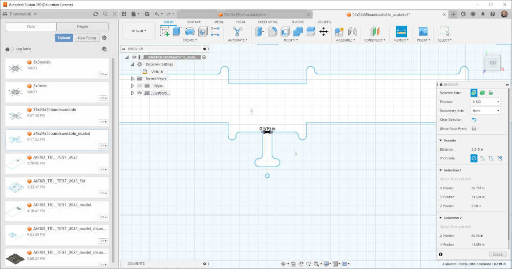
That’s a little too wide of a gap! However, I plan to sand and prepare the surface with sealant and paint, so I think I’ll go with this…in the interest of time :)
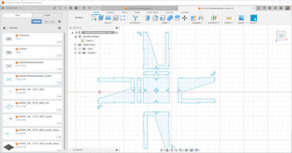
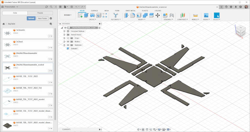
Next, I will make these sketches 3d models, so we can export them as SVG files; I know, crazy, right!? But it works and it is much better than drawing this myself ;) So, here we go extrude!
Extruded! Woo Hoo!
Now we need to export these beauties into SVG format, so here we go. We’ll start in the middle and spiral outward.
Center:
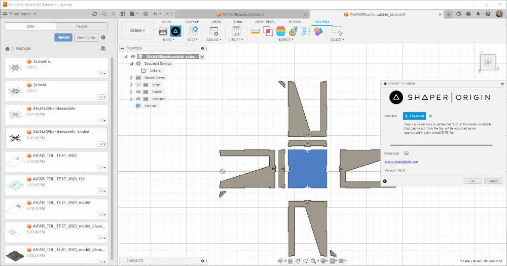
I had to export them individually the same way I did the center, but I will not drag you through each one. The center took up most of the real estate, so I had to make 4 boards to make them fit.
So, what did we just do? We used the Origin Utility to save each piece as a SVG file to import into Easel. It works…I’m sure of it ;) Let’s see:
So I made a large real estate because I am confident this will work, and that’s how much I want to play with…let’s see what happens:
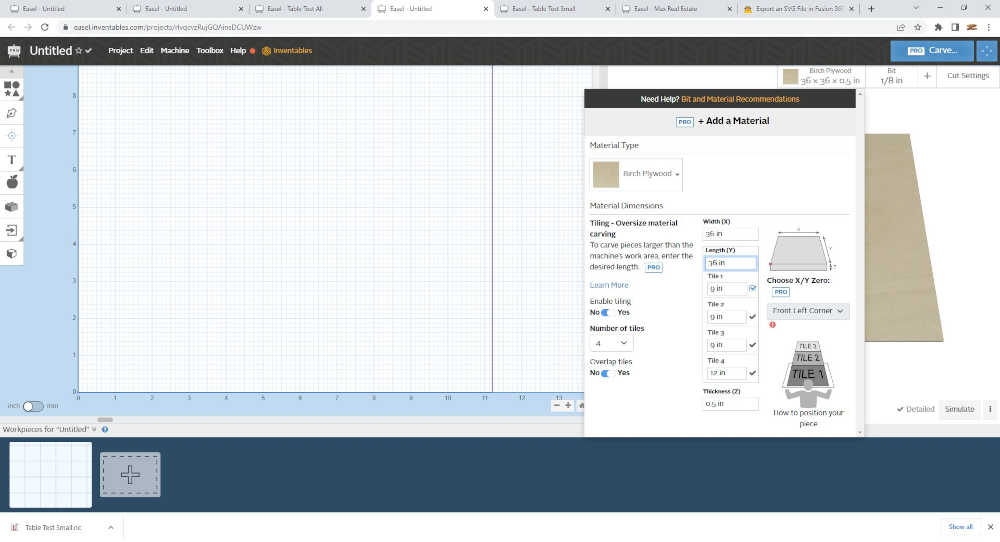
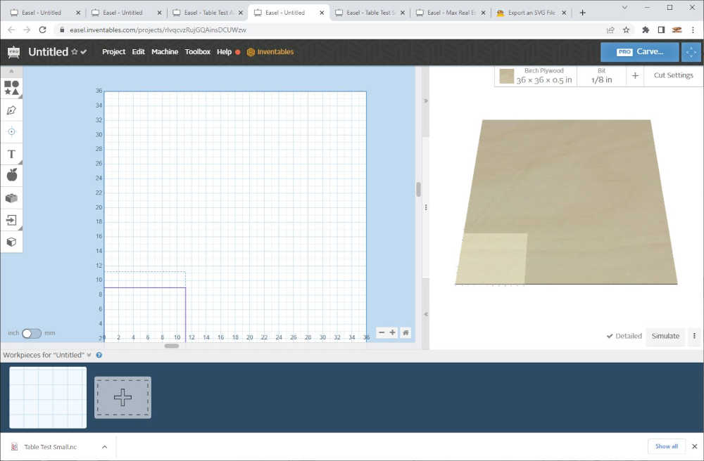
The table top took up a 3x3ft area and the support took up another. How will the legs fit!!? Well, I expanded the real estate to 4x4ft. Let’s see if I can make them fit :)
I was able to fit 2 legs into the real estate. we’ll call it top two table legs.
Now let’s get the rest!
Conclusion: I have demonstrated the workflow of taking a file produced in Processing 3, modifying the parameters, exporting to DXF, Inserting into Fusion 360, Scaling to compensate for material thickness, exporting to STL using Origin Shaper Tool, importing into Easel Pro, setting up fixture tabs, converting the holes into drill holes within Easel Pro, selecting the material and tool size (feed rate, plunge rate, depth per pass), exporting as g-code NC file, opening in Makerverse and sending to the MakerMade M2 CNC machine. This is a tedious process, but after doing this multiple times while documenting I enter “flow” mode and lose track of time while enjoying the process :)
I made another table, but did not document the process. I used an 1/8” endmill to mill the holes in a separate file, then milled the parts using a 1/4” endmill using the same feeds and speeds as the 1/8” endmill to be conservative. The table turned out fairly well, but the material was thinner than expected, so the fastening screws were necessary. I use this table to support my new MakerMade Mini CNC500.
Next Spiral Starting from Inspiration
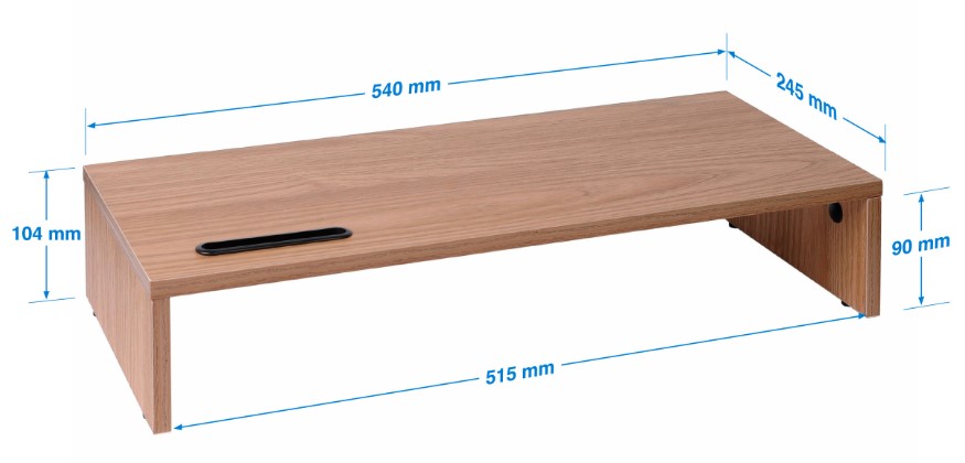
- I really needed to get a grip on designing with CAD tools starting with inspiration and transferring it on to a blank page. With the guidance of my Remote Instructor, Pablo I began with the below furniture for inspiration.
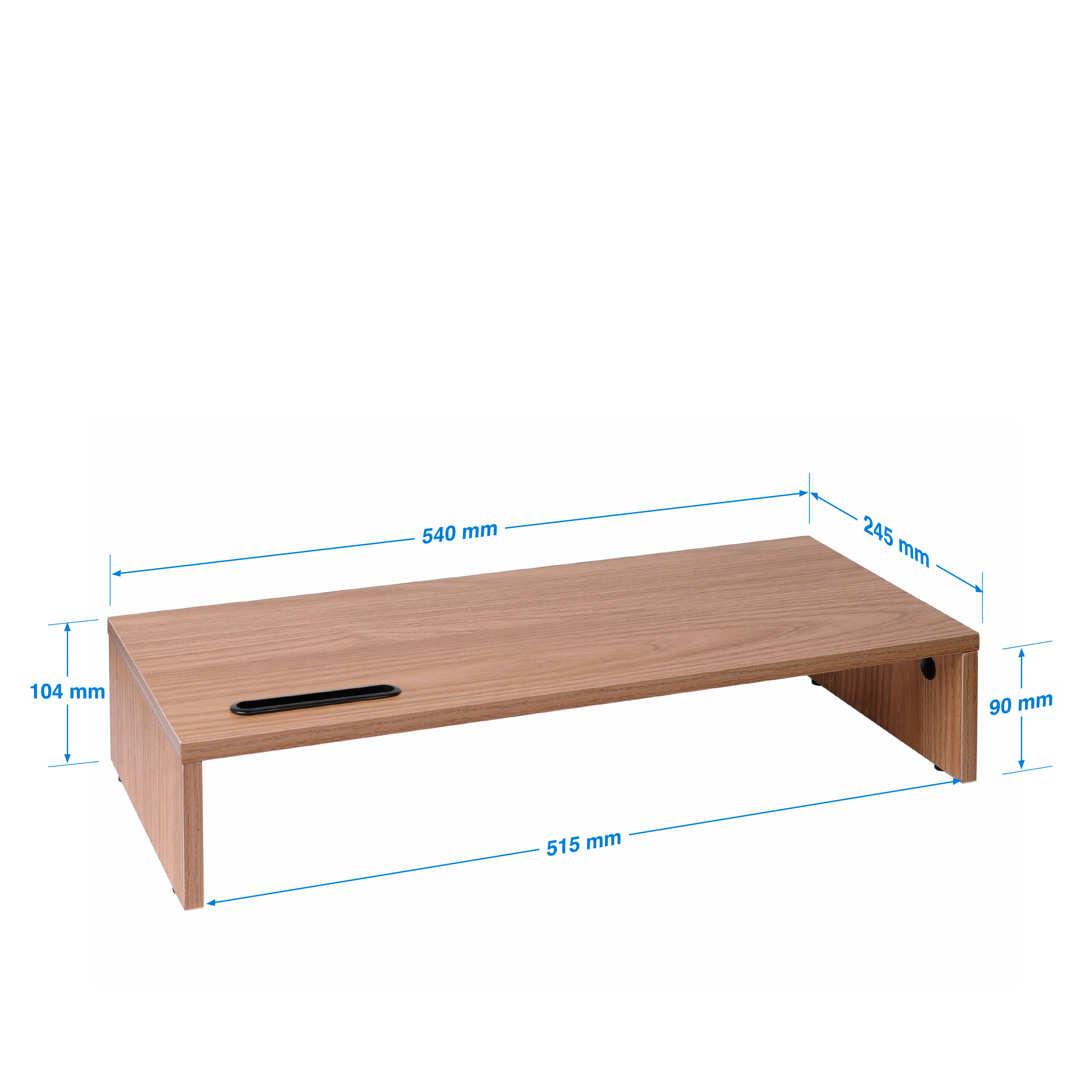
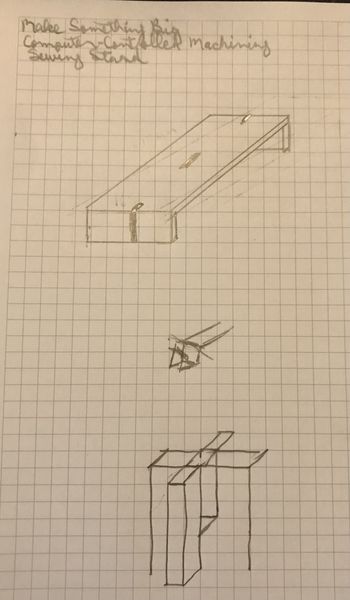
- The requirement was to design something simple that has joints like a computer shelf. So I started doing some sketching. My intent was to make a stand I could sit on my portable table to use my new sewing machine in the Fab Lab. This is what I came up with.
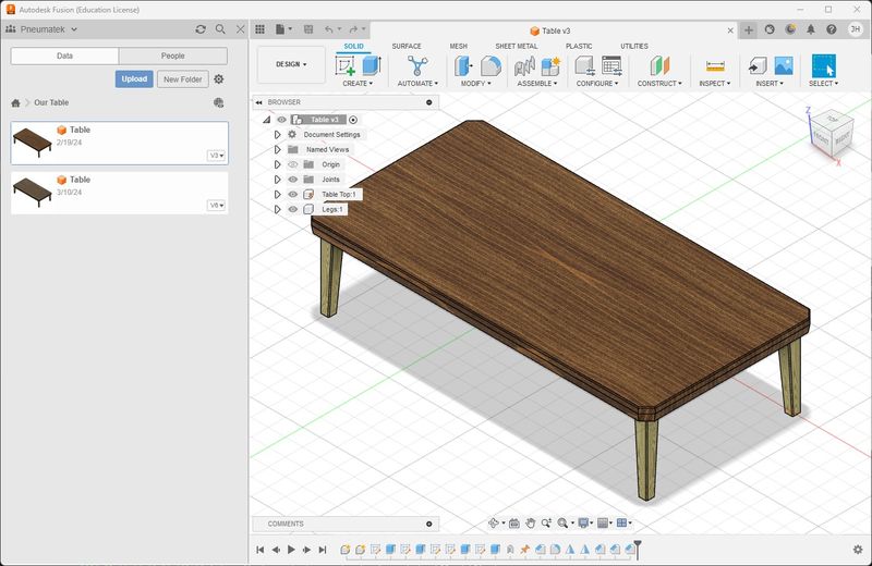
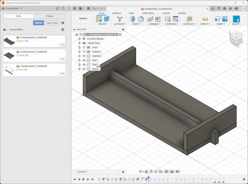
- I had difficulty conceptualizing the joints on paper, so I went to the CAD software, Fusion 360, to try to get a better idea of what to do. I have a little more experience in CAD after going through the tutorial Fusion 360 - Model and Assemble a Table with Legs (2023). This is the final model.
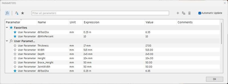
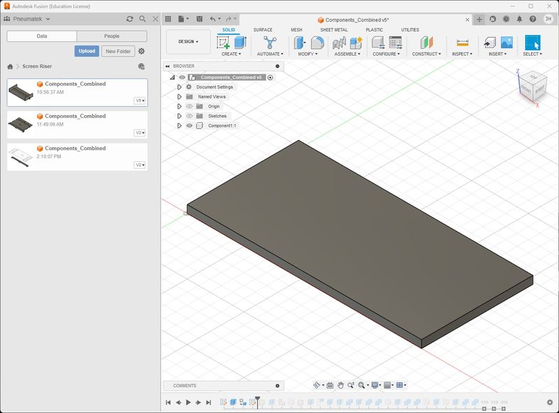
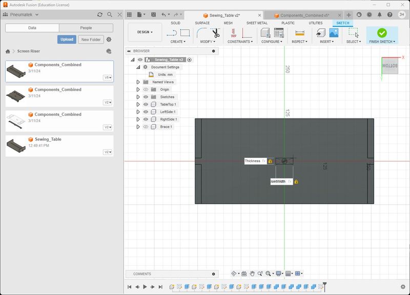
- So first I made the parameters.
- Then I made a sketch of the table top and extruded it.
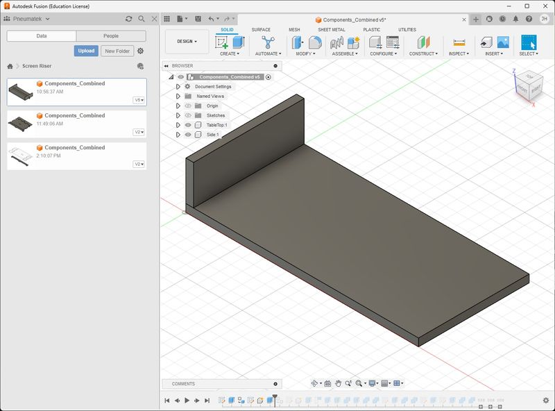
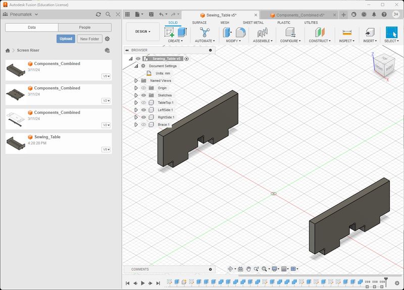
- Then I sketched and extruded one side on the edge of the table top.
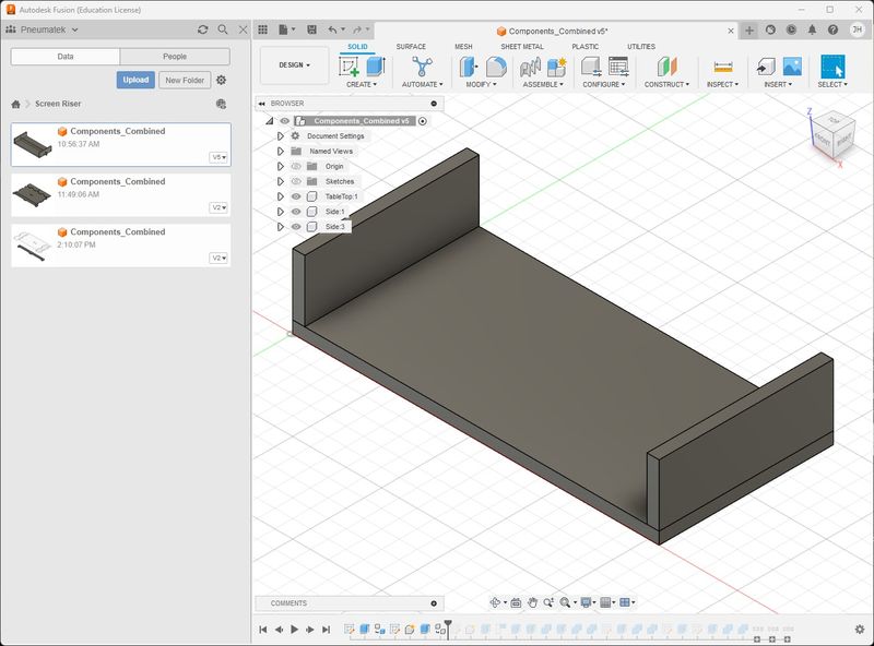
- And made a copy for the other side.
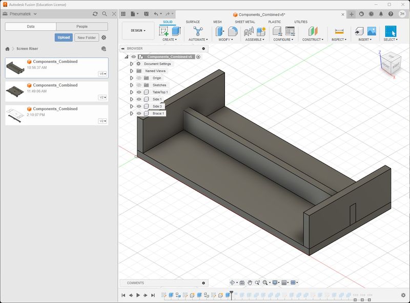
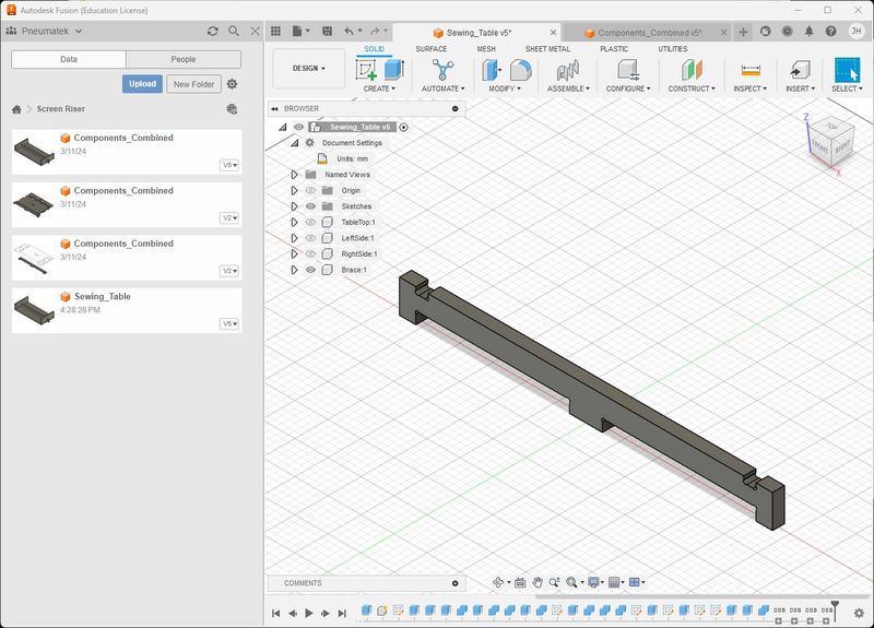
- I thought a brace would be good for strength and tying the table together.
- I also thought about the making of joints, so I thought it would be better to blend the parts and cut away what I needed to remove and join them. I’m not sure how to do that, but it makes sense to me.

- Too hold the sides to the brace, extending the brace was necessary, so I used the extrude tool to do this.
-
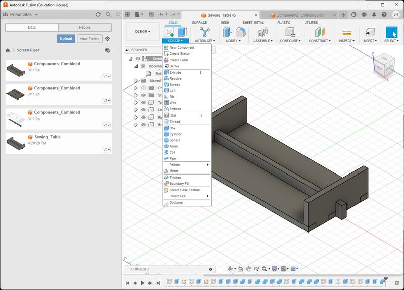
Pause for a moment…like a day or more. I had to find something else to do or I would go crazy, so I started looking at the CNC tutorial on the Fab Academy Class Site. That led me to a page that mentions DogBones and I remembered the lessons I had from the MAKE: Design For CNC book I referred to earlier. It was stagnant in my mind, but still there. So I did a DuckDuckGo search for “designing dogbone joints in fusion 360” and discovered a familiar name Luc Hanneuse and I felt like I had arrived at home. Thank you Luc and Wikimal.Archive! This plug-in was just as useful and encouraging as the Shaper Origin Export plug-in.
-
However, I still had to figure out how to cut slots that would use the dogbones. I did the tutorial I mentioned in mid-February and made the table. My knowledge became stagnant and forgot most of what I did. If you don’t use it, you lose it…fast at my age. I was really frustrated and reached out for help, but had to wait until after the weekend for the help to arrive. So, I went through the tutorial again and took notes ;) It really helped and gave me confidence to wrestle through this assignment. I remembered some of the examples Neil showed in class during CAD week; specifically combining parts and using boolean expressions to accomplish goals. Combine is the tool that pulled me out of the pit of despair.
-
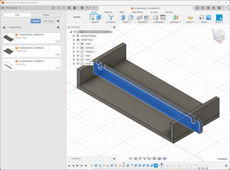
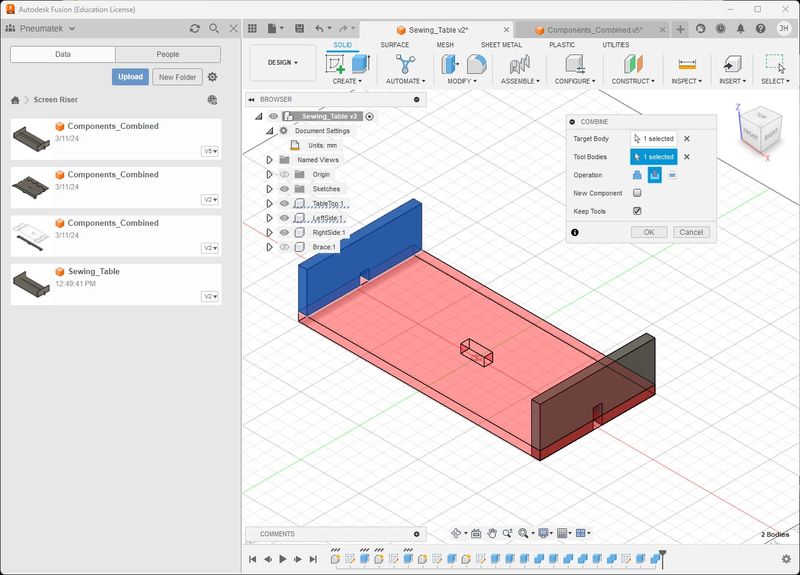
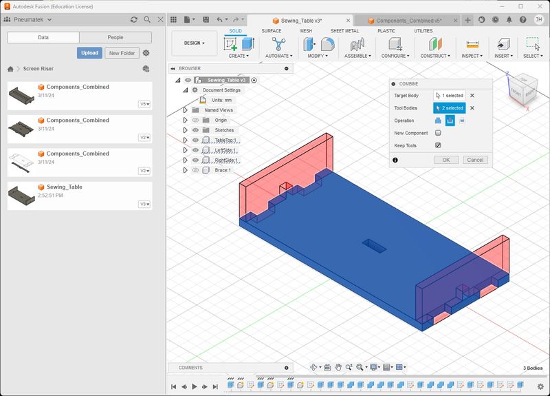
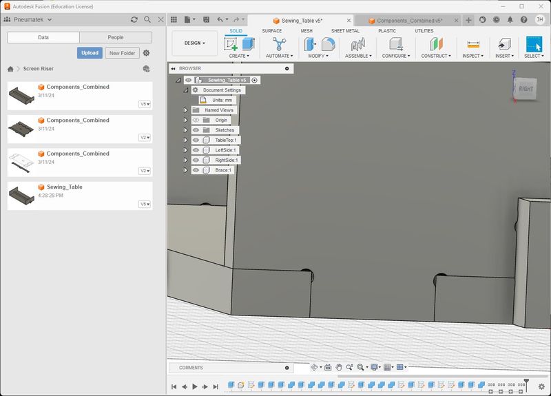
I went through several iterations with the Combine Tool and didn’t know what I was doing or where I was going with it, but I was seeing the immediate results I needed to push on. This is what I saw first.
-
The above image showing the Brace is from the last iteration of designing this table. I displayed it by using the timeline and move to the different steps in the design “after the fact”. The day before, I purchased the material and cut it to size the following morning. Turns out that this batch of plywood was thicker than the last, so I had to adjust the Thickness parameter. Unfortunately, the parametric design did not work as expected, so I had to completely redesign the Sewing Table. The following steps were documented throughout the next iteration.
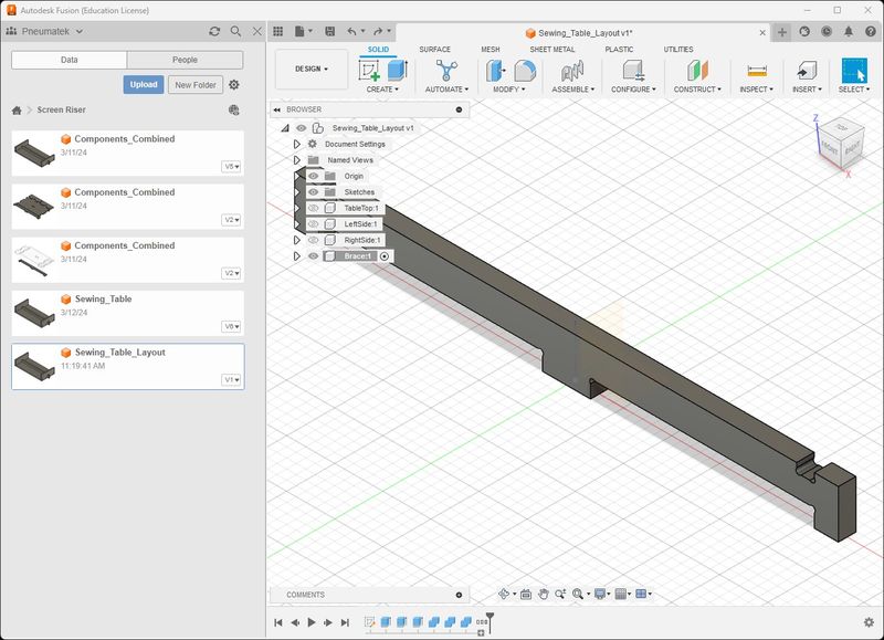
-
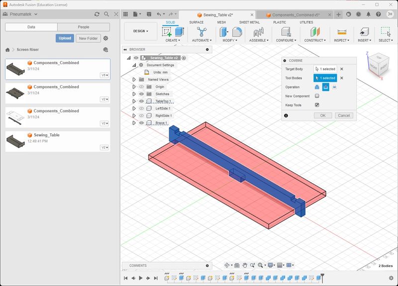
The Combine tool requires selection of the Target Body and the Tool Bodies. I selected the Sides as the Target Body (Blue), then the Brace as the Tool Body (Red), Checked the Keep Tools checkbox, and used the Cut function. Clicked OK. This cut a slot in the Sides. Then I hid the Brace and extrude the slot down Thickness/2. This made the slot smaller with the intent to use the Sides as the Tool Body to cut the Brace. There may be an easier way, but this is how I figured it out.
-
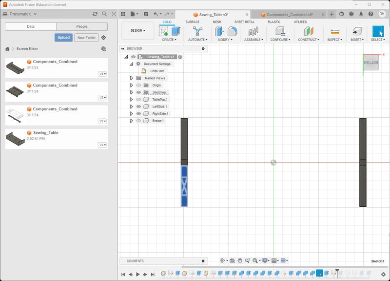
The next step was to make a joint with the TableTop and Brace. I made a sketch on the TableTop with the Brace hid. I extruded into the TableTop the -Thickness parameter to make a hole.
- Then I made the Brace visible and hid the Sides. Below you can see the Combine Tool in action with the TableTop cutting the Brace.
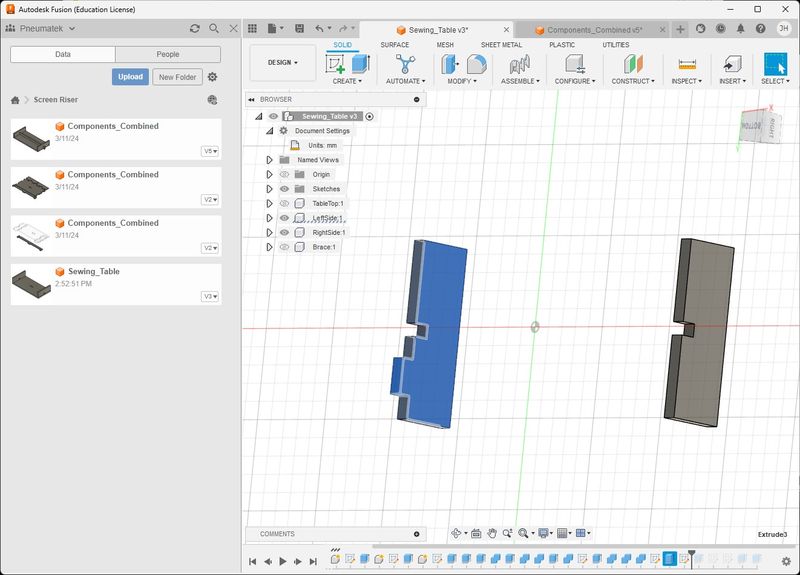
- Now I use the TableTop to cut the Sides. I show the LeftSide done and the RightSide is the same.
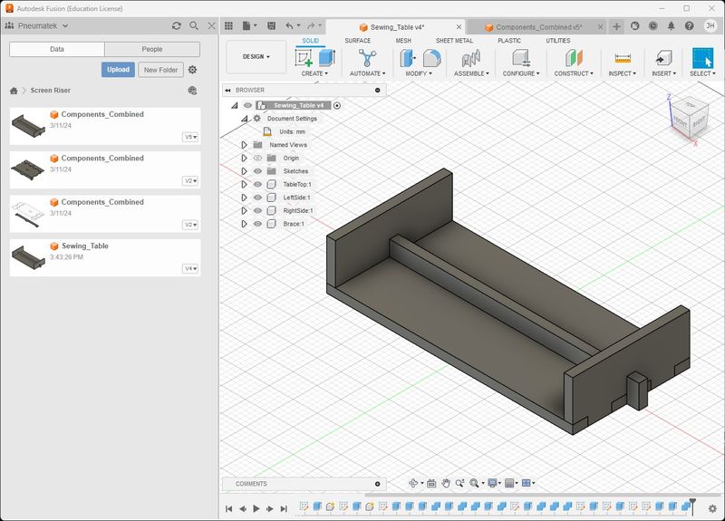
- The next process is to make joints between the TableTop and Sides. I hid the TableTop and made sketches on the Sides to extrude the Thickness parameter. The joints are located in the middle of the 2 areas separated by the Brace joint.
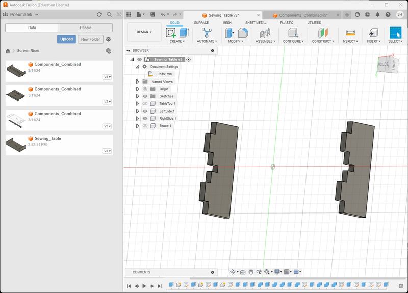
- I made the TableTop visible and used Combine to cut slots in the TableTop with the Sides as the Tool Bodies in a single action.
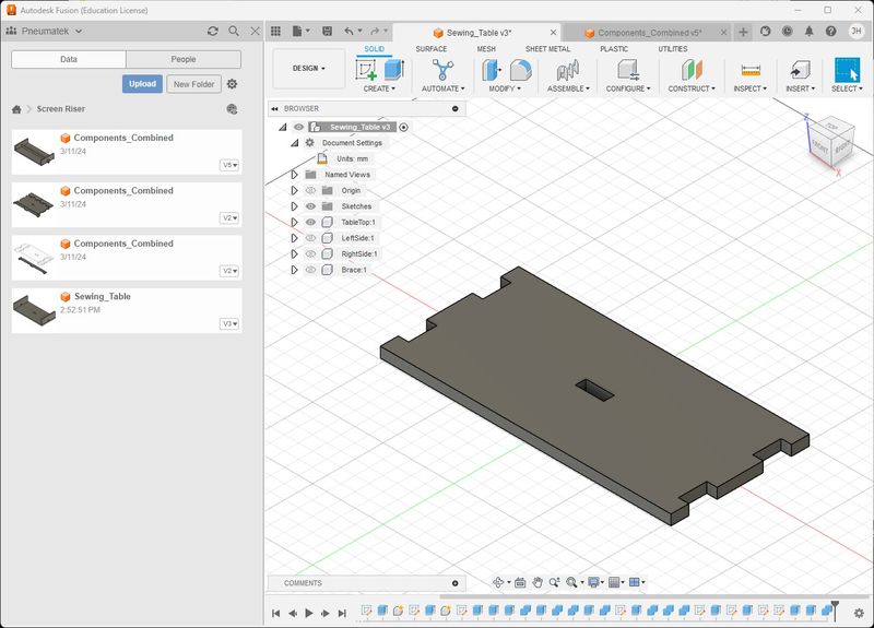
- This is after all parts were cut using Combine.
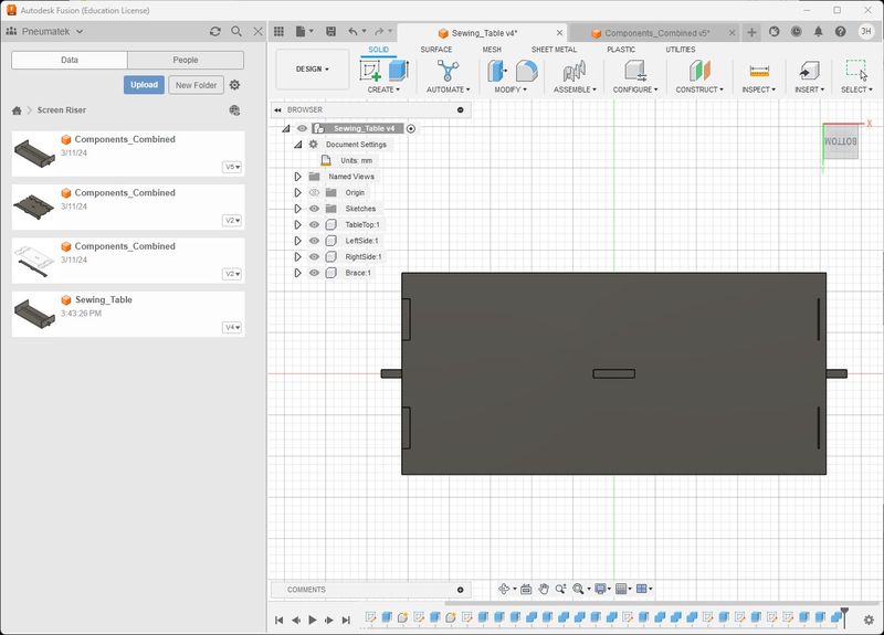
- At this point I wanted to make sure my model would endure a change in material thickness. Above is at 18.3mm Thickness. This is with a Thickness of 10mm.
-
Looks like I have some debugging to do in the next spiral :) So I put the thickness back to 18.3mm since that is my current material. Now I will insert the DogBones.
-
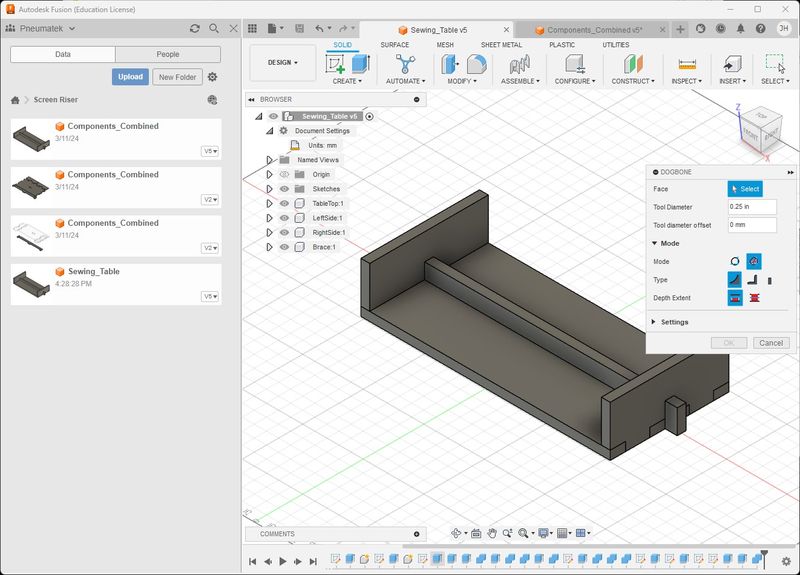
To do the DogBones in Fusion 360, I downloaded Windows installation file and ran it, then I checked to make sure it was installed properly.
-
The developers did fantastic work with this tool. I don’t think the process could be easier. Click Dogbone.
-
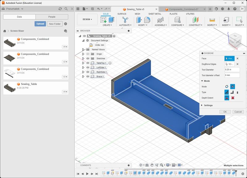
Set your Tool Diameter and any offset, Select the Faces. Click OK. I did have some faces missed so I hid all parts but one and applied dogbones to individual faces.
- Faces selected.
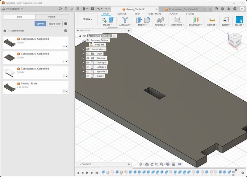
- TableTop DogBones
- Sides DogBones
- Brace DogBones
- Here is a closeup view
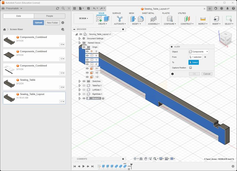
- The next step is to orient the parts for export. I found a great help on YouTube called Part Orientation In Fusion 360 | Four Ways To Do It. I chose the second way by using the Align Tool. I hid all of the components except for one. I will demonstrate the Brace that I have selected. Notice that I have the Origin visible; this is necessary to see the plane to align with.
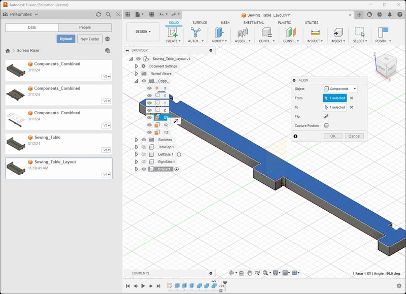
- Modify > Align > Select a Face
- Select a Plane (I chose XY) to lay it horizontal. Hover over the Plane listed under Origin it is easier. The part will reorient > Click OK
-
Now I Click Position > Capture Position. This places it in this position for export.
-
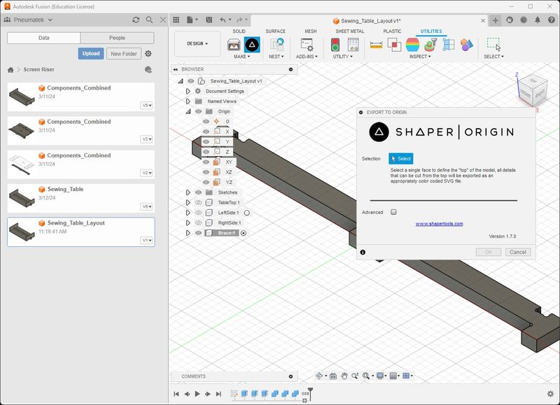
Click Utilities > Export to Origin
- Select the horizontal face > Click OK
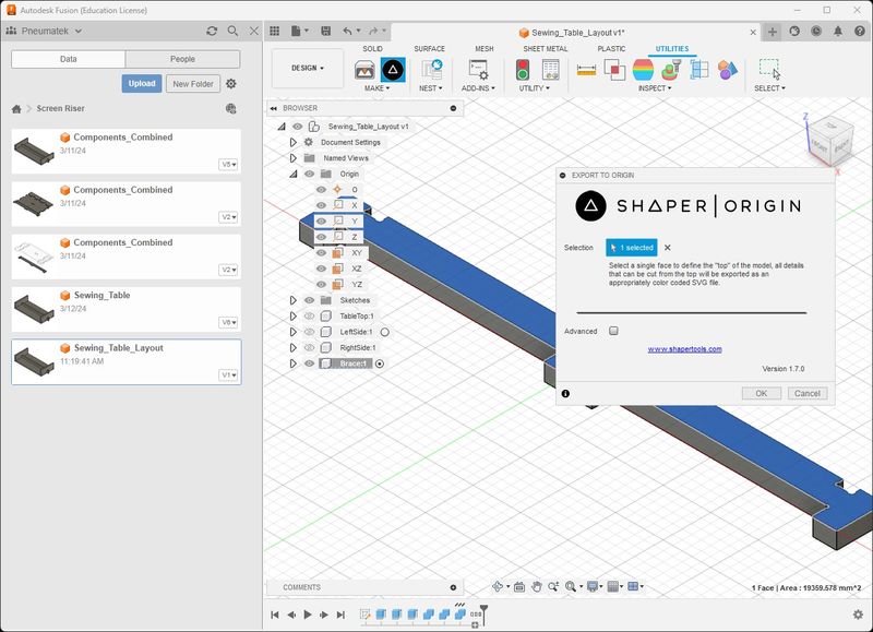
- Save it with an appropriate name and location
- Import the Brace into Easel Pro as STL
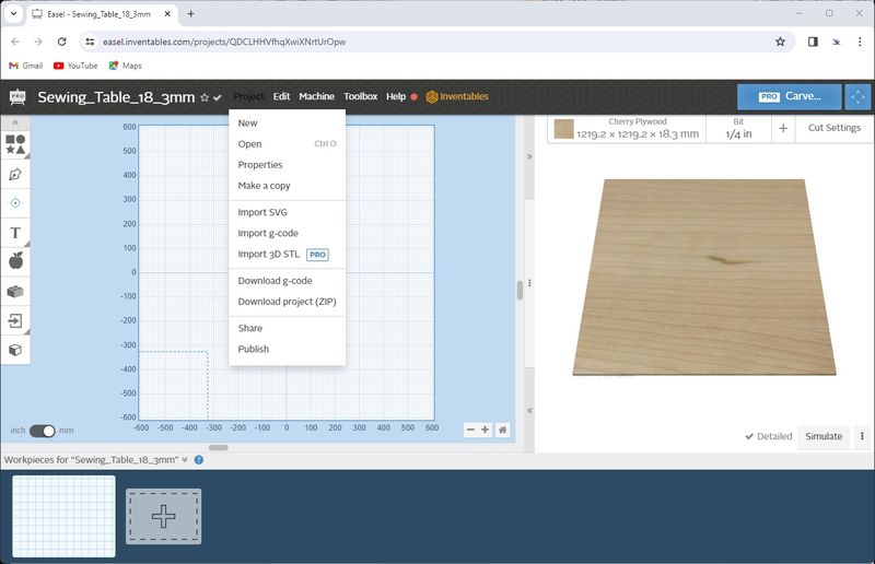
- Select the Brace
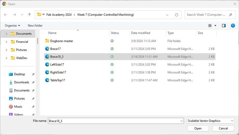
- Leave the original size
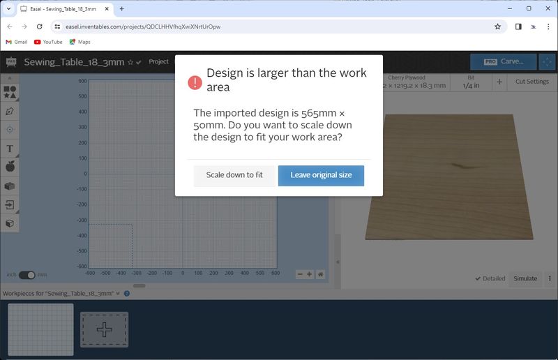
- Brace Imported
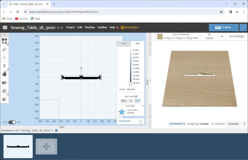
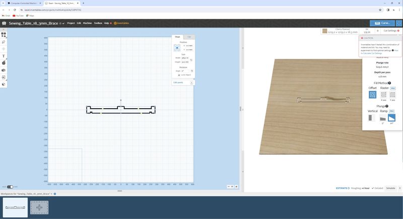
- Adjust settings for Cut as shown
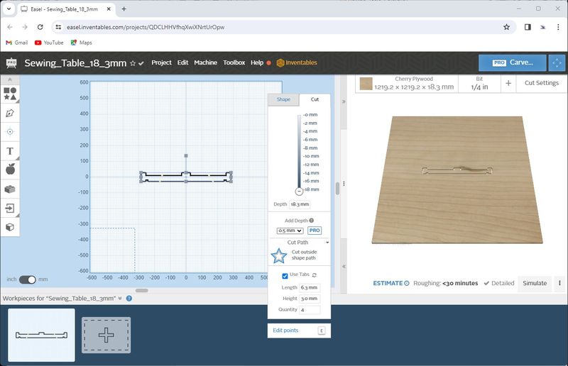
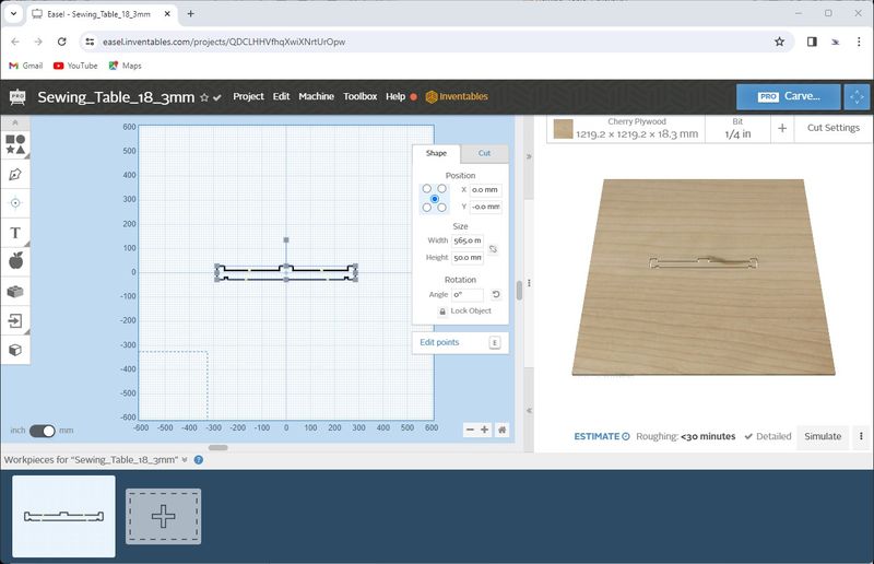
- Adjust settings for Shape to Center
- Check the Cut Settings for the endmill being used. Notice that I am using a 1/4” endmill and feed rate, plunge rate, and depth per pass is manually set as the same as the 1/8” endmill to be conservative.
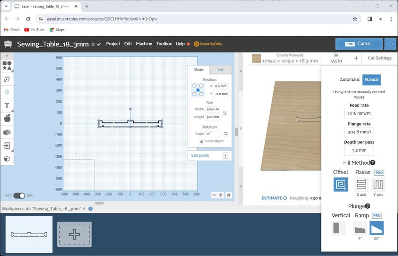
- If I set the Cut Seetings to Automatic, these are the settings I get and you can see the red exclamation mark next to Cut Settings. I’m not comfortable with those settings; that’s why I used the conservative settings from the 1/8” endmill.

- When I click on the red exclamation mark, this is the Caution message.
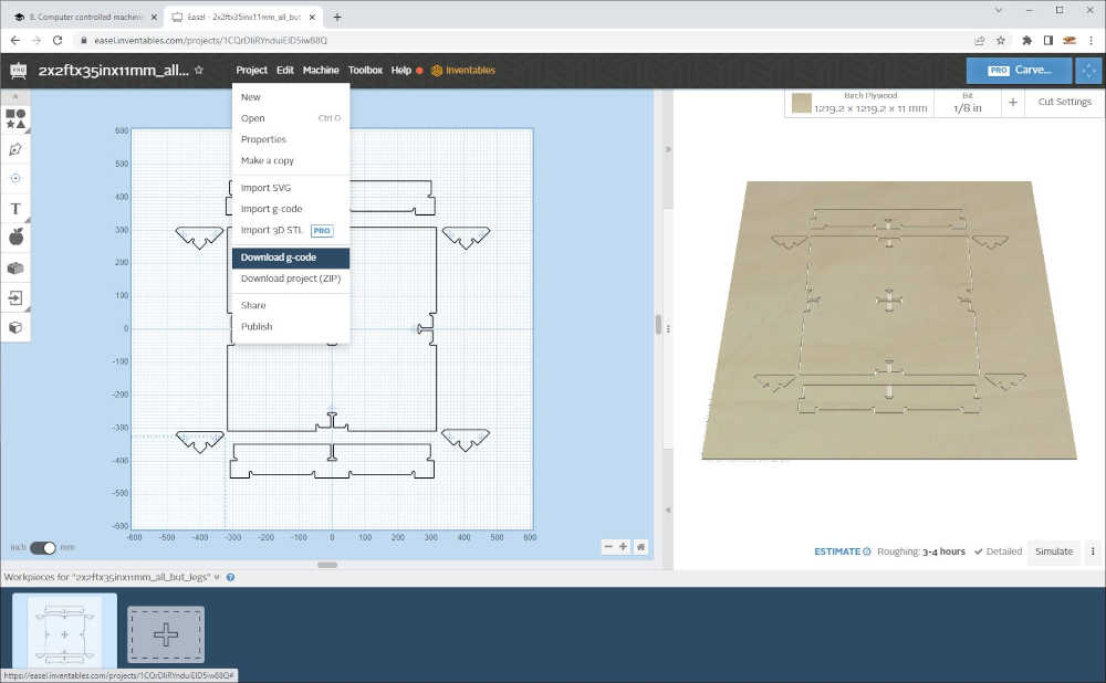
- After I have imported all of the parts, I export Gcode by Clicking Download g-code.
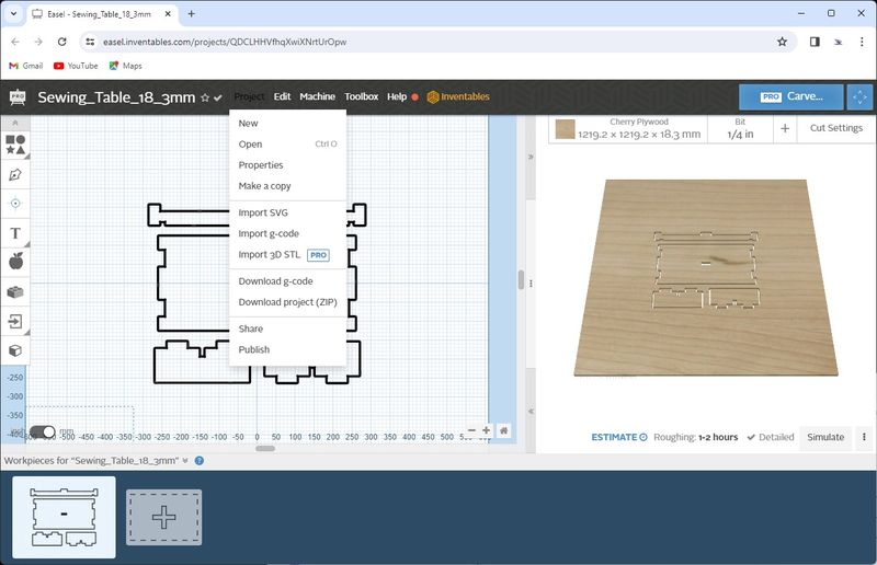
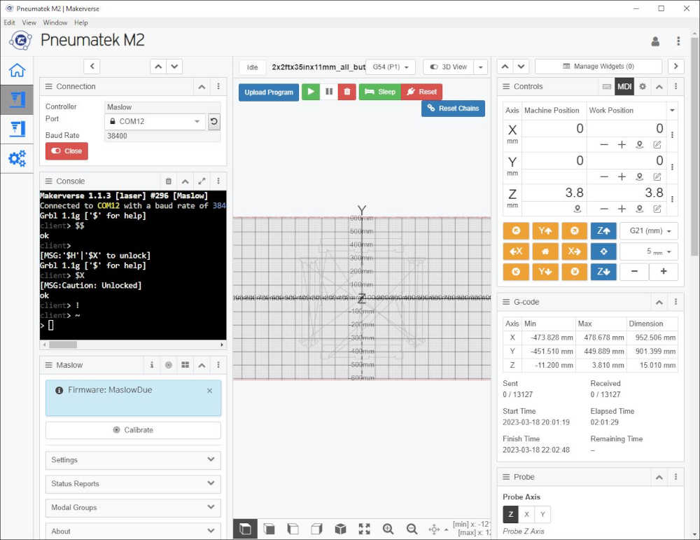
- Open gcode in Makerverse as shown below.
Documented how you made your CAM-toolpath:
- Documented how you made your CAM-toolpath:
Once the part is brought into Easel and positioned, the process of making the toolpath is determined by the Material Size and Type, the Bit Size, and the Cut Settings. To export the g-code, you Click Project > Download g-code:
The actual toolpath is generated in Makerverse when the g-code is uploaded to the CNC controller by Clicking Upload Program and selecting the .nc file:
On Design Day, we observed machining safety while in safety uniform; although it was a completely digital day. Designed a parametric table and transformed it into g-code. You saw the digital results. This weekend, on Fabrication Friday and Saturday, we will transforms these digital bits into atoms…woot!
Described problems and how you fixed them:
- Described problems and how you fixed them:
There are problems and their associated solutions throughout this documentation, but this is a good place to start.
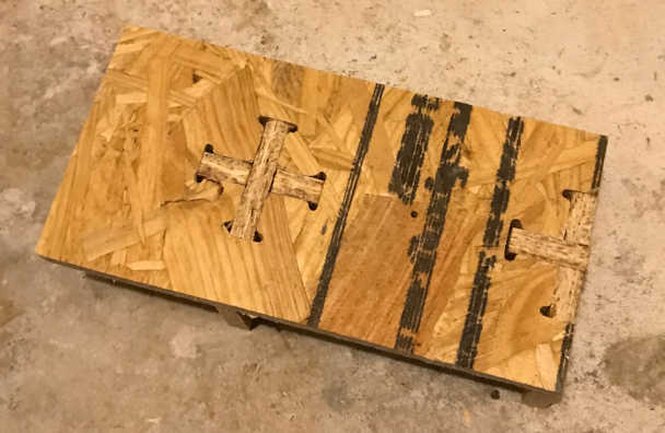
I really wanted to test my theory/workflow before I jumped in on the table, so I cut the whole test part first. So glad I did! There were issues I have not resolved yet…the parts did not fit like I wanted them to. So here is the result:
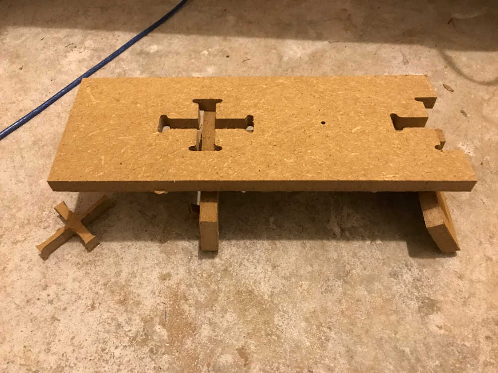
I am not sure how it happened, but the slots on the cross piece were skewed and the test part will not assemble. Back to the drawing board!
This time I just flowed through the process without taking pictures. I followed the same workflow, but gleaned valuable insight into the process. Processing > Fusion 360 > Easel Pro > Makerverse. A four step process with many places to make mistakes. The first was scaling:
Scaling - when I imported the DXF files from the processing program into Adobe Illustrator, the parts were huge. I tried it in AutoCAD, still huge. Fusion 360 was next. Still huge, but now I can measure it easily. It is exactly 10 times the size it should be. Internet to the rescue:
This was the answer to the cause:
- “A DXF file is a unitless file type so when Fusion reads the file, by default, it will assume that the file is in centimeters unless otherwise specified during insertion.”
I exported it in mm where a meter is 1000 mm. Upon import, the part was 10 meters. That’s a big table! About the size of my house :)
This was the solution: There are several options, but the easiest is starting with a New Design, set the units to mm, then Insert DXF. You can change units after this, but it’s best to know what you started with. DXF is unitless!
After going through the design process again, I felt confident that my understanding would carry me through to a successful outcome. However, before cutting the table, I thought it would be a good idea to cut the test part again. I started cutting at 12:30pm and finished an hour later. The result was disheartening, but I knew I had not applied my newly found knowledge of design to the test part yet. I was running out of time, so I redesigned the table instead of the test part. I learned a lot more going through this again and felt even more confidence as I prepared to sent the bits to cut the atoms.
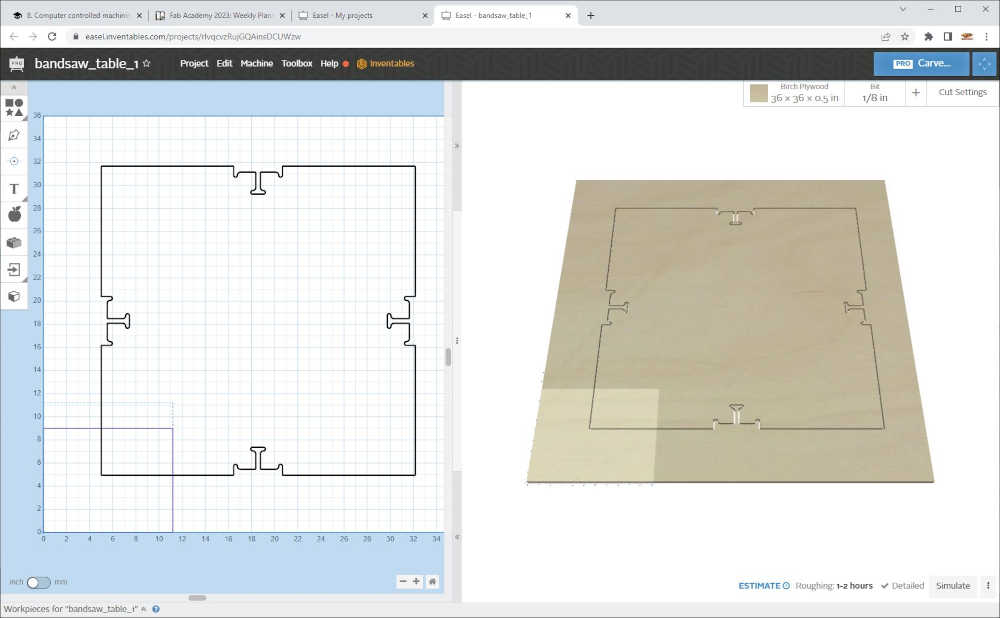
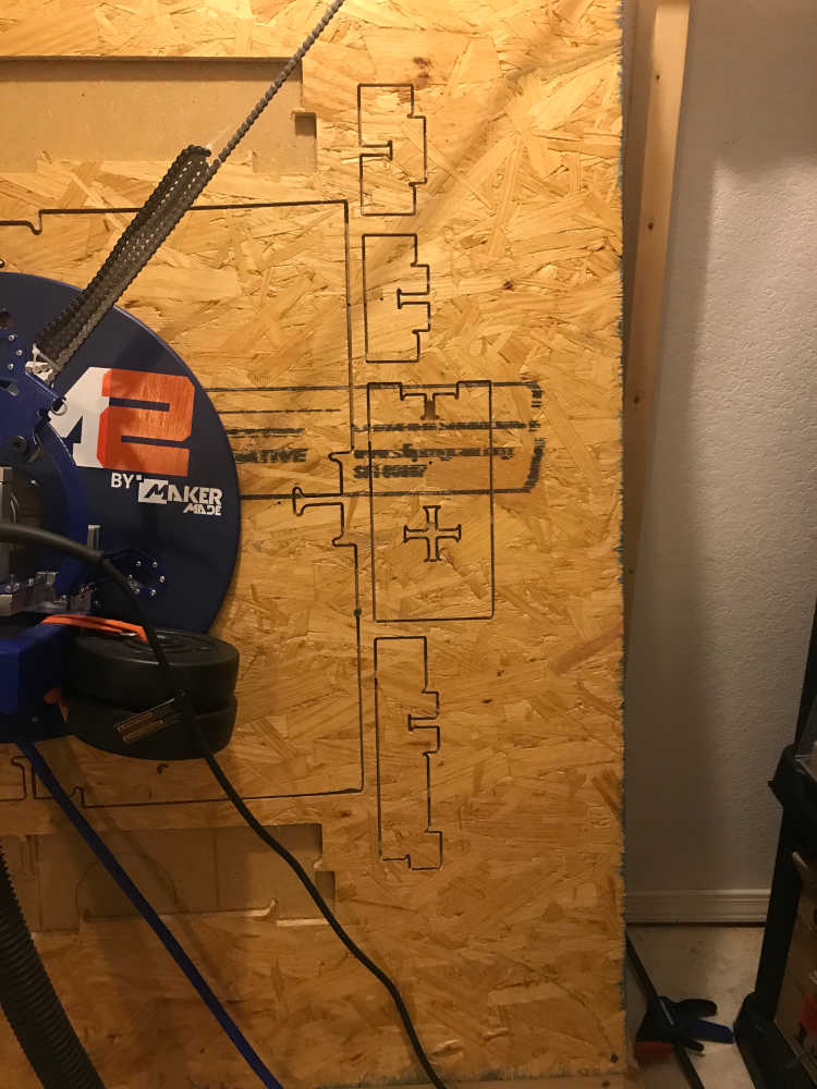
I began cutting at 4:52pm
and the center cross cut nicely;
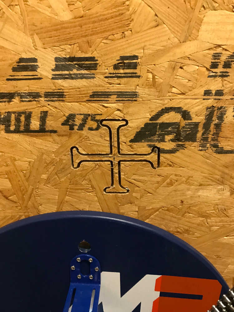
then for the 2x2ft table perimeter. As it cut, I could monitor progress while I prepared the other parts digitally. As the cutting progressed, it appeared that the top line was sagging. I was hoping it was an optical illusion, but, as you can see, it is indeed sagging. Although, the bits were cooperating, the atoms were not. More learning to do.
I decided to go through the calibration process, although I was running out of time. I only had enough material to finish the “make something big” project. The results of the edge calibration were hopeful, but the software said I could do even better with the precision calibration; that is what I proceeded to do. Since the sled was already in the lower left corner, I thought I would begin there. More on that later. I will say I had a CRASH like you would imagine, but not as boring as an endmill breaking. You had to be there and I need a camera set up to capture events like this! I fixed it, but I need to calibrate again and I’m running out of time :) Arrrghhh!
Using Makerverse, I recalibrated and received an excellent report on the second round. I decided to give it a try with the supports and feet of the table. I could immediately see the difference and the straight cutting lines. Success!!
I went through the design process for the test part again and had better results due to the recalibration
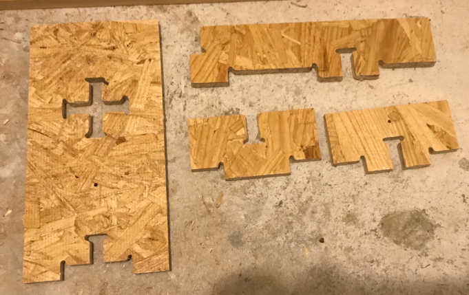
While cutting the supports, the top part was cut first. Since I was watching I caught the job when the tabs broke and the part moved. I immediately paused the job and removed the part. On the next support I paused the job and installed fasteners so the part won’t move. Another problem I encountered was the dogbone cutouts tend to move and cause unnecessary stress on the endmill. To correct this in the future, I will add tabs at the top on the dogbone cutouts. SOLUTION: Instead of 2.0mm thick tabs, I used 3.0mm tabs, this solved both problems.
Another problem is the inconsistency of the OSB material. The edges are thicker than the center; this gave me an inaccurate cutout for the dogbone cutouts. SOLUTION: In Design for CNC, I was instructed as follows: “Using calipers, measure the thickness of your plywood sheet in at least four places — near the edges of the sheet — as indicated by TA, TB, TC, TD” (Rohrbacher, Gary; Filson, Anne; France, Anna Kaziunas; Young, Bill; France, Anna Kaziunas. Design for CNC . Make Community, LLC. Kindle Edition.) I was further instructed to record this information and do the same for each sheet to find the greatest thickness and call this measurement TMAX. This value changes from one sheet to the next as well as from one vendor to another.
With this information you determine the scaling percentage S = TMAX/TNOM where TNOM is the thickness built into the CAD model. This is the measurment of all of the dogbone cutouts. The authors recommend saving the models with the Scaling percentage in the filename. The table test part was designed for a material thickness of 19mm (TNOM) and the maximumum thickness of the OSB material was 11.2mm; this resulted in a Scaling percentage of 0.589 This is a considerable amount and would drastically change the dimensions of the final part. However, this is a test for my CNC milling machine with a table test part. Future designs with have a TNOM closer to the TMAX of the material.
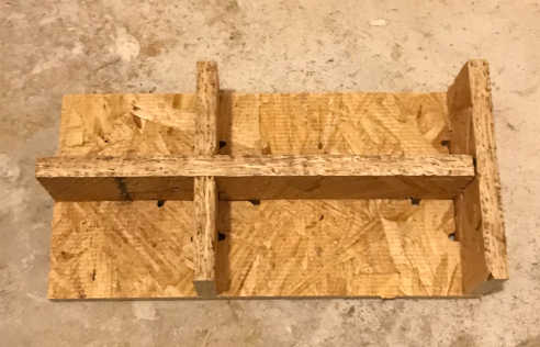
After scaling the table test part, I exported using the Origin Utility to a SVG file, imported into Easel Pro, and saved as a NC file. Bringing it into Makerverse, I was able to cut successful parts:
I found that scaling in Fusion 360 requires the CAD model to be 3D, so it must be extruded if it is a flat cutfile.
Now that I am confident that I can properly design and scale parts and with the capabilites of the CNC milling machine, I am ready to “make something big!” with the proper dimensions to press fit a table made of OSB material.
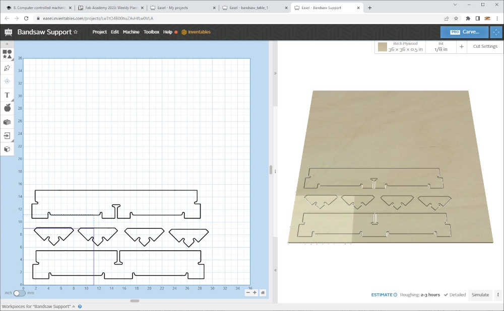
I went through the design process again from the beginning, I am becoming more confident and learning more every spiral. I redesigned the table and included the supports and feet in the same job as you see above where I documented making the CAM-toolpath.
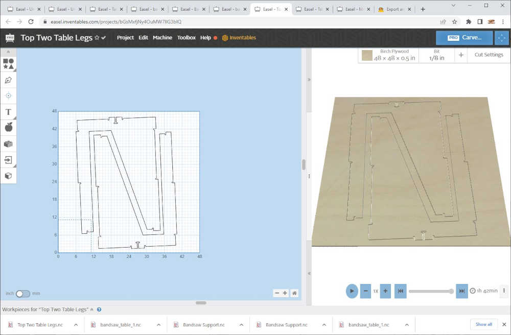
This is a screenshot of two table legs after I centered them in Easel Pro:
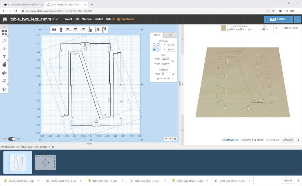
You can see in the image where the drill holes are located. I was very tedious to place the drill holes. Although the Processing app places holes in the model, Easel Pro requires the cut path to be on, inside, or outside the shape; that would make a hole larger than I wanted, so I replaced the holes with drill commands in their place. I used the drill reticles to determine the exact location, recorded x and y, deleted the hole and type in the x and y value to place the drill point. Additionally, if/when the part is moved, the drill point must be selected as well or the placing will be lost.
The sewing table that I designed and milled using a 1/4” endmill with the same settings I have been using successfully, did not have drill holes because I thought the joinery would hold it together; I was wrong. Although the brace had a snug fit, I ended up using 2 screws on both ends to hold the legs on. I should have used an 1/8” endmill for this smaller table…lessons learned. Use a smaller endmill for smaller pieces and use screw holes until experience is acquired.
Documented how you made something BIG (setting up the machine, using fixings, testing joints, adjusting feeds and speeds, depth of cut etc.):
- Documented how you made something BIG (setting up the machine, using fixings, testing joints, adjusting feeds and speeds, depth of cut etc.):
Setting up the machine for cutting is as follows:
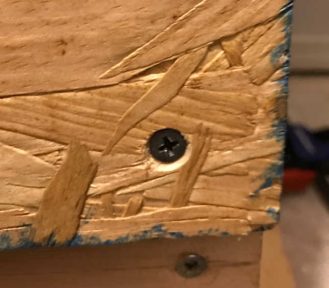
- Place and center the material on the table and fasten the corners
(be sure to countersink the screw holes to prevent the sled from sticking on the screws)
-
Since I am programming tabs into the part, fixing is only required on the corners of the material.
-
The joints were tested in the test part, so the joints should fit.
-
The feed, speed and depth of cut are calculated automatically with the Easel Pro software and included in the exported g-code.
-
Connect the USB cable to the computer > Plug in the power supply for the CNC Controller > Open the COM port connection > Zero the Endmill and back it out 5mm
-
Upload Program in Makerverse
-
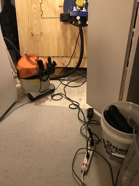
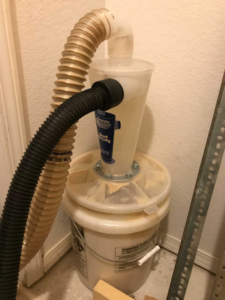
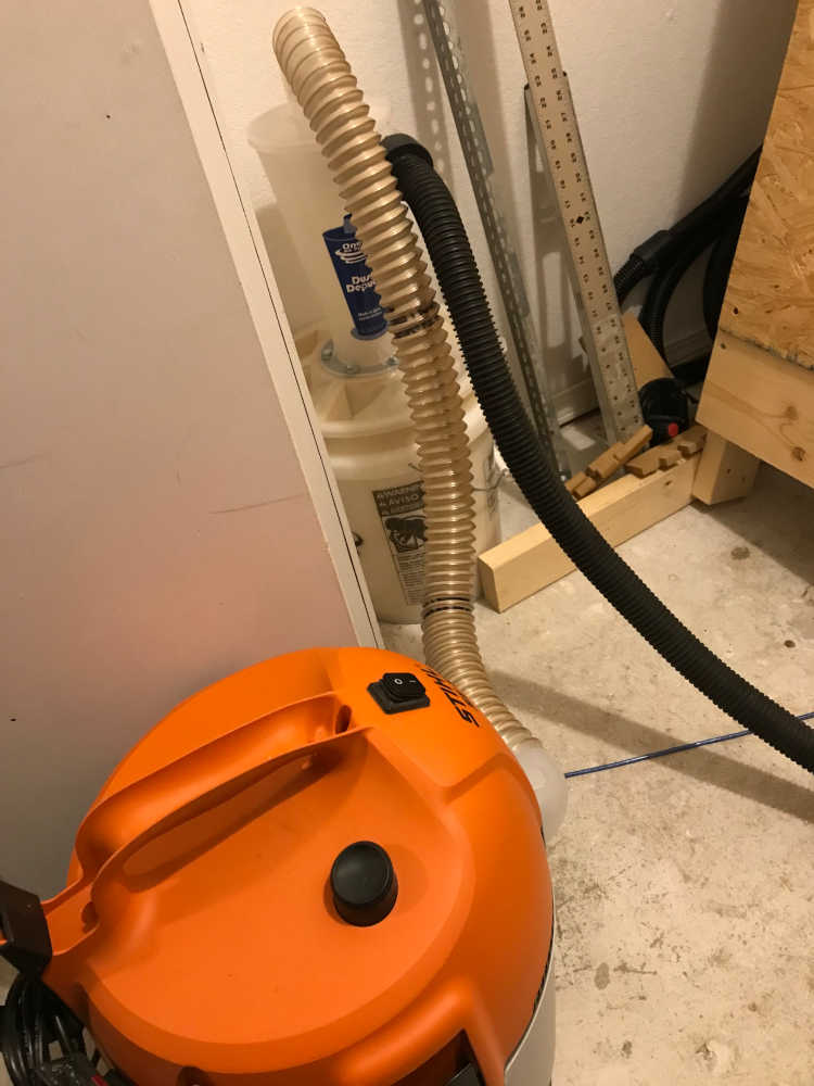
Turn on the dust collection vacuum.
-
Turn on the Router and ensure the recommended speed setting of 5 is set
-
Click on the Play button and watch the fun begin!
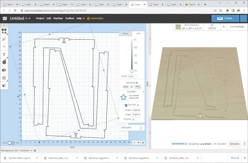
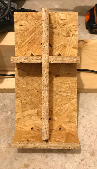
While running the final table, my initial measurements have me wondering whether this is a viable option: parametric design > CAD > NC file. The lines look straight, but the lengths are questionable. Additionally, I set the cut to 11mm with a 0.2mm added cut; this appears to be insufficient in some parts, so 0.5mm added cut will improve the post processing.
After trying the table top and supports to see if there would be a problem with the fit, I found that one support was longer than the other; this was suprising to me because I expected them to be the same length. My settings in the parametric processing app were 24x24inches, but the actual measurement is 24.25x25inches and the supports were calculated to fit the table top. Rotating the supports allowed me to find the proper placement.
Before I started cutting the legs I noticed the legs were off-center, so I centered them, changed added depth to 0.5mm and saved a new version of the files. I learned that you can select all and change the Add Depth setting all at once too.
Watching the cutting process throughout the first two legs and allowed me to see that the depth adjustment worked on the first leg. However, the second leg did not cut completely through in the lower right corner. I discovered that the lower right corner of the OSB was not flush with the waste board; this explains the problem. In the future I will be more diligent in making the material flush with the waste board. Additionally, I found large splintered wood partially blocking the suction tube for dust collection. I removed the blockage before the next job. OSB tends to fall apart after some of the bonding material is removed.
Included your design files and ‘hero shot’ of your final product:
- Included your design files and ‘hero shot’ of your final product:
Design Files SketchUp, Fusion 360, Processing, Easel Pro
Hero Shot