Mechanical Design, Machine Design
This week I will collaborate with my group to design a machine as well as plan and make a machine. This will include:
Mechanical Design (part 1 of 2)
- Design a machine that includes mechanism + actuation + automation + application
- Build the mechanical parts and operate it manually
- Document the group project and my individual contribution
Machine Design (part 2 of 2)
- Actuate and automate your machine
- Document the group project and my individual contribution
Learning outcomes
- Work and communicate effectively as a team
- Design, plan and build a machine
- Analyse and solve technical problems
- Recognise opportunities for improvements in the design
Checklist
Documented the machine building process to the group page:
-
Documented the machine building process to the group page:
-
There are two types of assignments, mostly group and documentation of what I do as an individual. Since I am alone in my Fab Lab, I need to collaborate with someone, so I will work with my remote node. This is a team effort. All of my work will be documented here, but I will link to the group assignment page where the majority of work is documented.
Linked to the group page from your individual page as well as from group page to your individual pages:
-
Linked to the group page from your individual page as well as from group page to your individual pages:
-
During Fab Academy 2019 my remote node is Lorain County Community College Fab Lab. I will interact with my group remotely and collaborate with them during this assignment and document the team effort at the Group Assignments page
Shown how your team planned, allocated tasks and executed the project (Group page):
-
Shown how your team planned, allocated tasks and executed the project (Group page):
-
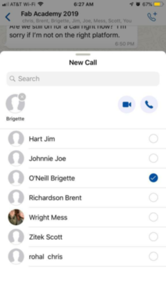
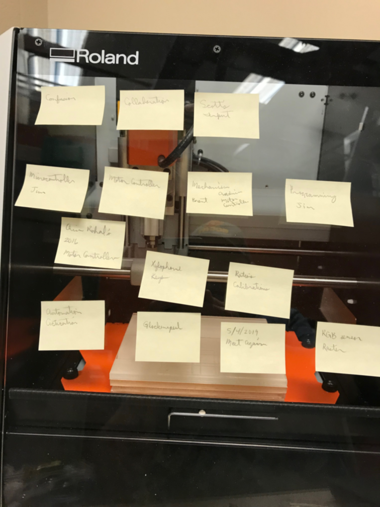
Discovery: Had a group meeting on April 20, 2019. This is when we planned and assigned tasks. I was comfortable with making the hello world boards, so I offered to take on this task as well as programming the board.
-
New Call List
- Post-It Notes
Described problems and how the team solved them (Group page):
-
Described problems and how the team solved them (Group page):
-
We have a section at the beginning of the Group page that discusses the challenges we had and how we overcame them.
Documented your individual contribution to this project on your own website:
-
Documented your individual contribution to this project on your own website:
-
Exploring:
-
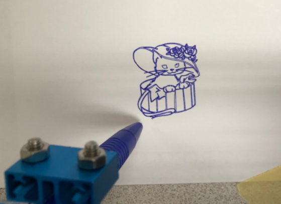
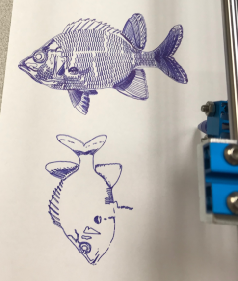
Since I cannot be with my group physically, I would like to work with as many machine concepts as I can, so that I can understand the control of output devices similar to our group project. This is XY plotter that I built on 12/24/2015, so it came in handy on April 21, 2019 to refresh my understanding of the machine concepts it contained. ~\Makeblock\GRemoteFull\GCodeParser_Makeblock Orion. Used GRemote.bat to load G-Code to XY Plotter.
-
XYPlotterBox
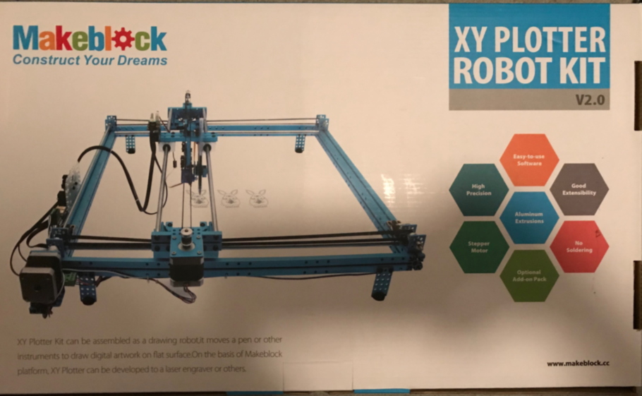
- Board
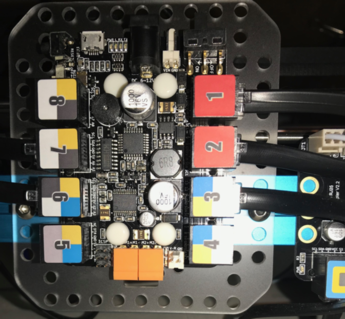
- Controller
- GCode
- Cat
- Fish
-
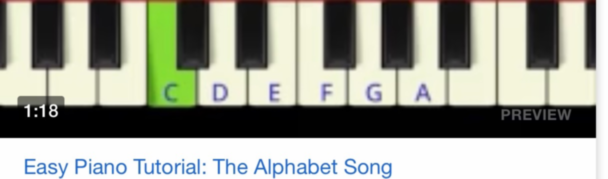
Music to play in the machine “Ah! vous dirai-je, maman”, Alphabet Song and Twinkle, Twinkle, Little Star have the same music. Only 6 notes.
-
Music
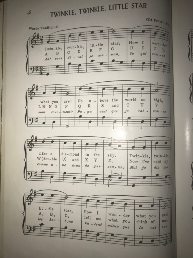
- Piano
-
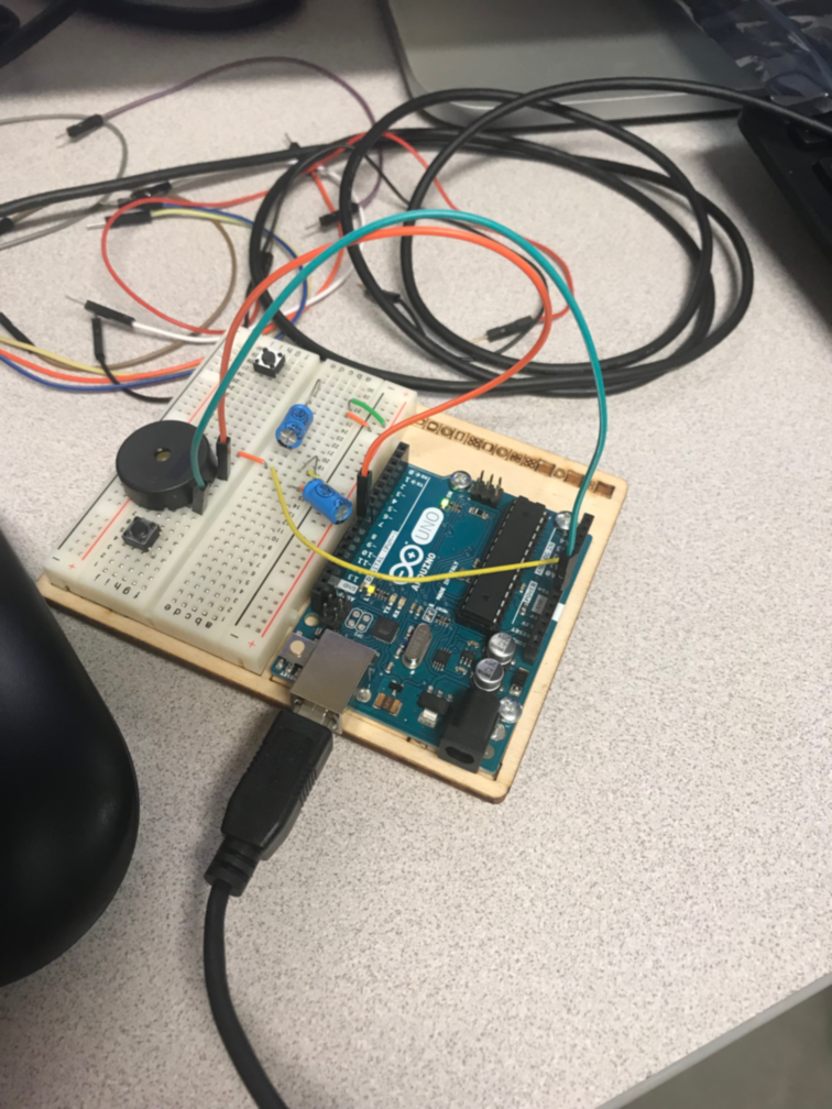
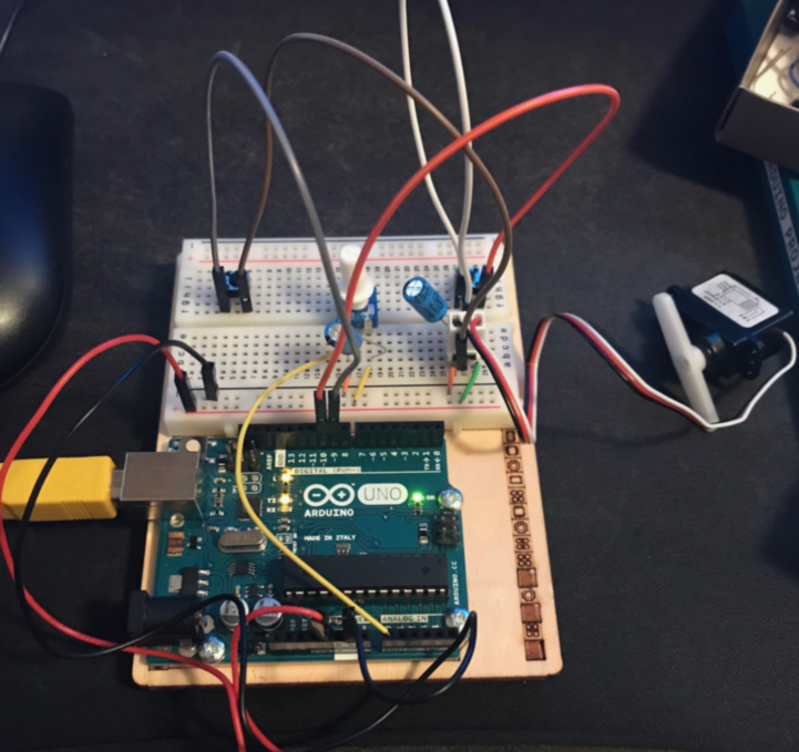
I also used The Arduino Starter Kit to learn how to make sound with a microcontroller as well as control a servo motor.
-
Arduino Sound Board
/*
  Melody

  Plays a melody

  circuit:
  - 8 ohm speaker on digital pin 8

  created 21 Jan 2010
  modified 30 Aug 2011
  by Tom Igoe
  modified 1 May 2019
  by Jim Hart


  This example code is in the public domain.

  http://www.arduino.cc/en/Tutorial/Tone
*/

#include "pitches.h"

// notes in the melody to play the alphabet song:
int melody[] = {
  NOTE_C5, NOTE_C5, NOTE_G5, NOTE_G5, NOTE_A5, NOTE_A5, NOTE_G5, 0,
  NOTE_F5, NOTE_F5, NOTE_E5, NOTE_E5, NOTE_D5, NOTE_D5, NOTE_D5, NOTE_D5, NOTE_C5, 0,
  NOTE_G5, NOTE_G5, NOTE_F5, 0, NOTE_E5, NOTE_E5, NOTE_D5, 0,
  NOTE_G5, NOTE_G5, 0, NOTE_F5, 0, NOTE_E5, NOTE_E5, NOTE_D5, 0,
  NOTE_C5, NOTE_C5, NOTE_G5, NOTE_G5, NOTE_A5, NOTE_A5, NOTE_G5, 0,
  NOTE_F5, NOTE_F5, NOTE_E5, NOTE_E5, NOTE_D5, NOTE_D5, NOTE_C5, 0

};

// note durations: 4 = quarter note, 8 = eighth note, etc.:
int noteDurations[] = {
  4, 4, 4, 4, 4, 4, 4, 4,
  4, 4, 4, 4, 8, 8, 8, 8, 4, 4,
  4, 4, 4, 4, 4, 4, 4, 4,
  8, 8, 4, 4, 4, 4, 4, 4, 4,
  4, 4, 4, 4, 4, 4, 4, 4,
  4, 4, 4, 4, 4, 4, 4, 4
};

void setup()
{
  // iterate over the notes of the melody. Added sizeof() to compensate for melody changes:
  // https://www.arduino.cc/reference/en/language/variables/utilities/sizeof/
  for (int thisNote = 0; thisNote < (sizeof(melody)/sizeof(melody[0])); thisNote++)
  {

    // to calculate the note duration, take one second divided by the note type.
    //e.g. quarter note = 1000 / 4, eighth note = 1000/8, etc.
    int noteDuration = 1000 / noteDurations[thisNote];
    tone(8, melody[thisNote], noteDuration);

    // to distinguish the notes, set a minimum time between them.
    // the note's duration + 30% seems to work well:
    int pauseBetweenNotes = noteDuration * 1.30;
    delay(pauseBetweenNotes);
  }
    // stop the tone playing:
    noTone(8);

  }

void loop() {
  // no need to repeat the melody.
}
- Servo operated by Arduino using a potentiometer on April 30, 2019
-
Refined:
-
Fabbed my first Servo Board on May 7, 2019
- Stuffed Servo Board, programmed, and tested on May 10, 2019
-
The C code provided by Neil worked, but I did not figure out how to tweak it to play our song. After 5 days, I decided to assemble my work to make a presentation.
-
Reconstructed the Arduino prototypes and tested while recording.
-
Rapid prototyped a drum to make sound with the Arduino servo circuit.
-
Production:
-
Since Neil said, “Where possible, make what you can in the lab (1:13:40), but it’s not a tight standard. The main goal is to link back to the work you did in the mechanical design week”; this week is actuation with automation. Although it is not what I wanted to turn in, it is something and a lot was learned.
-
I am assembling the results of my spiral development
-
End result: ATTiny44A Dual Servo Board learning from Neil’s success, but not ready to succeed, myself.
-
Video
You need to present your machine globally and/or include an aprox. 1 min video (1920x1080 HTML5 MP4) + slide (1920x1080 PNG) (Group page):
-
You need to present your machine globally and/or include an aprox. 1 min video (1920x1080 HTML5 MP4) + slide (1920x1080 PNG) (Group page):
-
LCCC Group Project
Listed possible improvements for this project (Group page):
-
Listed possible improvements for this project (Group page):
-
At the end of the Group page under Next Steps we discuss possible improvements for the project; such as, using the fabbed boards and making a base for the coppoer tines.
Included your design files (Group page):
-
Included your design files (Group page)::
-
The design files for the project are linked to the Group page under Laser Files from the designer under.
-
During Random Review, I was chosen and had an opportunity to talk about our Machine Design during the review at the 1:13:28 position in the Vimeo video. Neil seemed pleased with the project and the progress that had been made.
This is a continuation of the Mechanical Design week in Fab Academy 2022
Machine Building
The group assignment this week was focused on Mechanical Design and Machine Design.
Group Assignment
Mechanical Design (part 1 of 2)
- Design a machine that includes mechanism + actuation + automation
- Build the mechanical parts and operate it manually.
- Document the group project
Machine Design (part 2 of 2)
- Actuate and automate your machine.
- Document the group project
Learning Outcomes
- Work and communicate effectively in a team and independently
- Design, plan and build a system
- Analyse and solve technical problems
- Recognise opportunities for improvements in the design
Linked to the group page from your individual page as well as from group page to your individual pages:
- Linked to the group page from your individual page as well as from group page to your individual pages:
This is a link to the LCCC Fab Academy 2022 Machine Building.
Communication
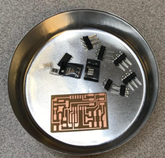
For this assignment we discussed possible machine ideas using Zoom and email for communications. We communicated with Scott, our instructor, through email to keep him informed of our ideas and progress. One idea was a cd player with vinyl cut designs on old cds that are read in to transform color to sound. We discussed this with Scott; he gave an example of designing and building a machine to load and unload CDs. He also mentioned that the typical project uses an off-the shelf controller to drive 2 or more stepper motor driven axes. Scott suggested a machine based upon 2 linear axes and an End-of-arm-tool (EOAT) designed to perform a certain purpose. We decided to use Cardboard Stages and have an EOAT to pick up magnetic distortions to make sound through the use of an amplifier.
We used what materials and parts were available at LCCC; specifically, stepper motors with lead screws built in. For the controller Scott suggested an Arduino Uno with a Stepper motor Shield; Jim ordered the controller parts so he could prototype and program the controller at his remote location.
Design, plan and build a system
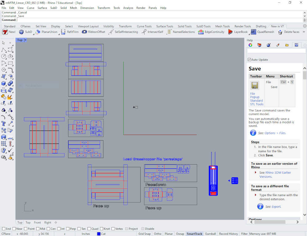
- Design - Using the Rhino Model provided by Nadya Peek, we configured a simple 2 axis stage to move our magnetic pickup over a surface area.
-
Plan - I used the Rhino files and exported the model from Rhino to Sketchup for further 3D design. I exported the cut files to Inkscape to make the cut files. Abby planned on using the files to cut the cardboard with a laser cutter; however, she decided to model and 3D print the stages intead of cutting them. The magnetic pickup will be made by Abby as well as the magnetic field generators for the surface area. I will use the controller and stepper motors to bench test and prototype the concept with my xy plotter; the software will be developed in the Arduino IDE.
-
Build - Stages, Controller, Pickup, and Sound
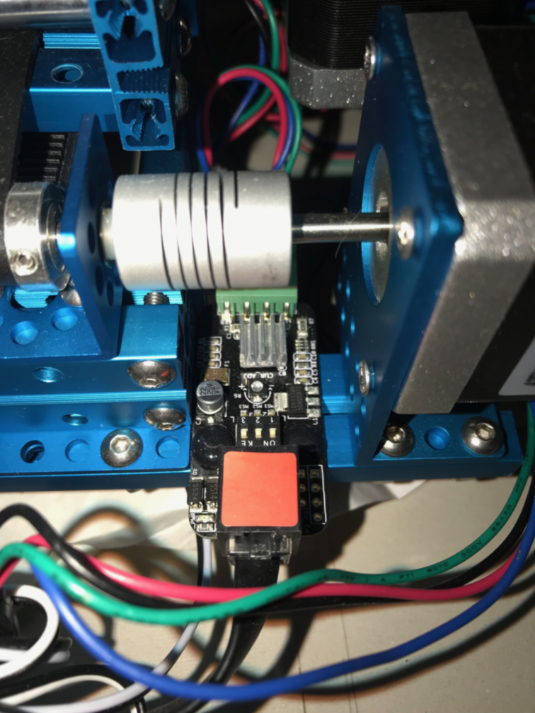
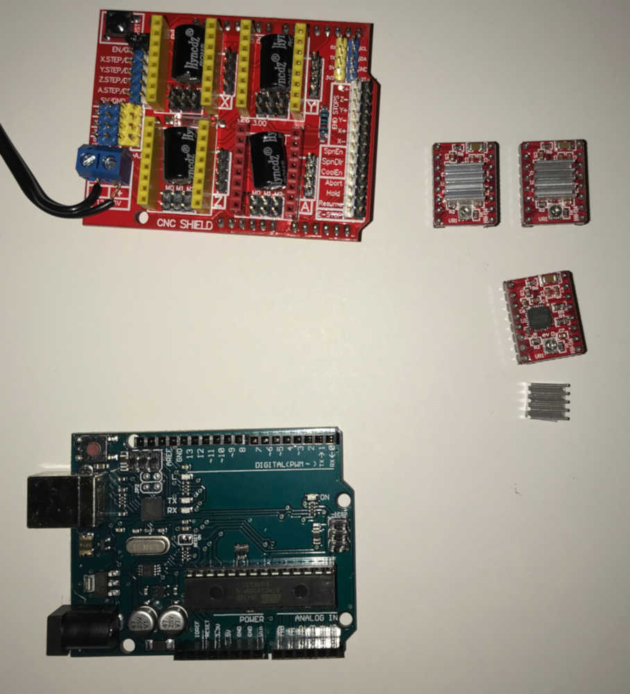
Controller - The Kuman CNC Kit has documentation on the website. I also watched a YouTube video by Electronic Clinic to help build the kit; there is also a written version of the instructions here I assembled the controller per the video and the instructions.
Controller Preassembly
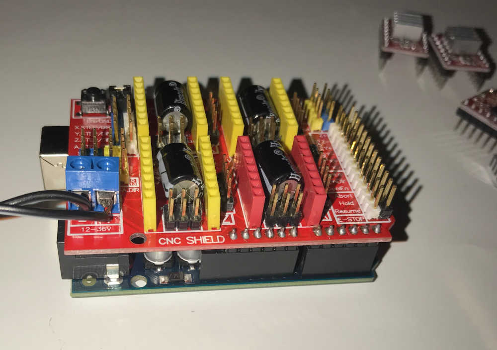
CNC Shield attached to Arduino UNO
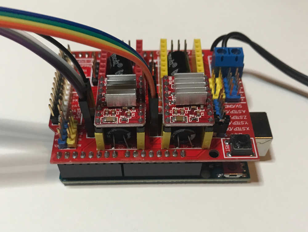
Controller wired to accept stepper motors
Controller connected to stepper motors and ready for testing
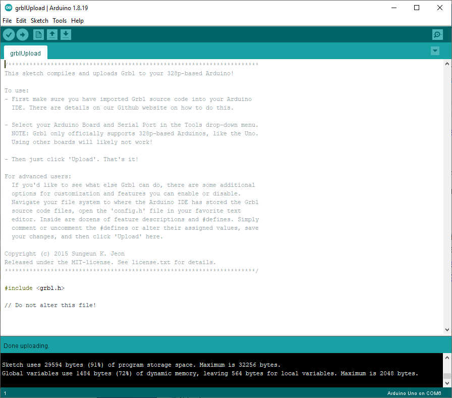
The Arduino IDE accepted the GRBL Library and uploaded the software flawlessly.
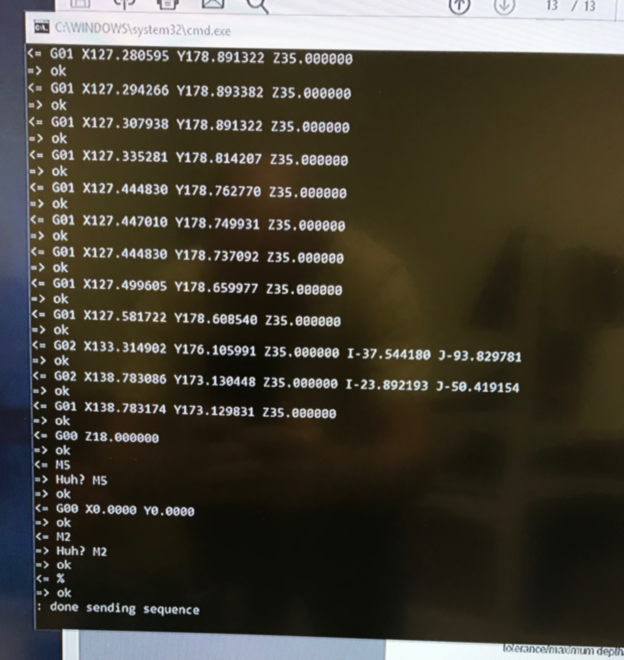
The instructions recommended Universal G-code Sender, so I downloaded and extracted the files. I ran ugsplatform64 located inside the bin directory, refreshed the Port and COM6 showed up,
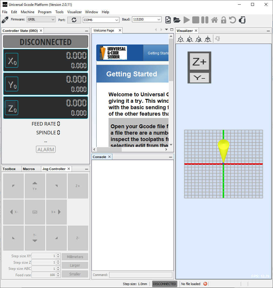
I clicked Connect and successfully connected to the Arduino and saw the G-code.
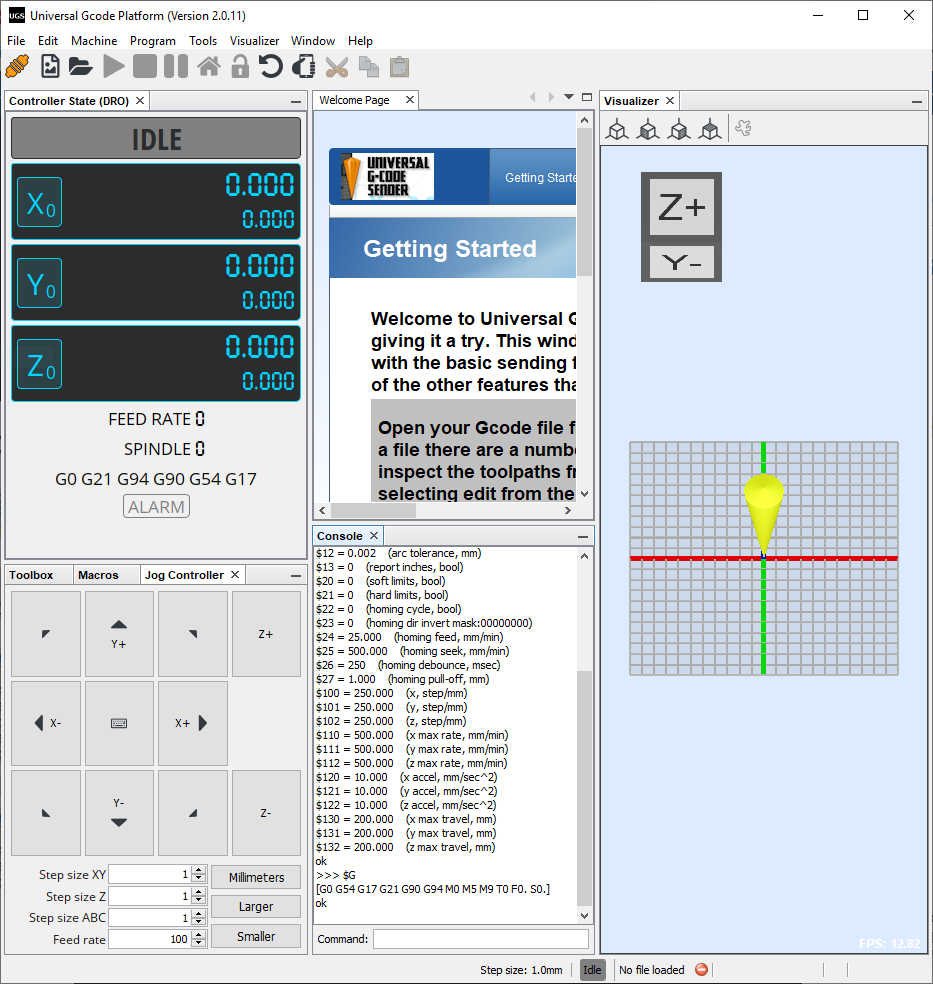
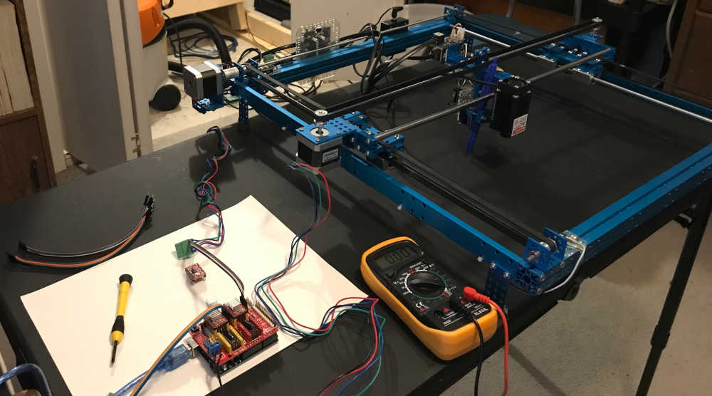
I had a problem with the first stepper motor driver; the x-axis stepper motor would not turn. I thought it may be the software, so I tried the ino code provided by Electronic Clinic, still no movement. I placed a different stepper motor driver in the socket and had success. I checked the Vref voltage and found it at 0.56 volts by using the negative power connection as a common and touched the potentiometer with the positive lead. I put the other stepper motor driver back in the socket, turned the potentiometer until the stepper motor responded, and then adjusted Vref to 0.87 volts.
After properly adjusting the Vref, the stepper motors were very responsive. I tested the x-axis and y-axis movement successfully.
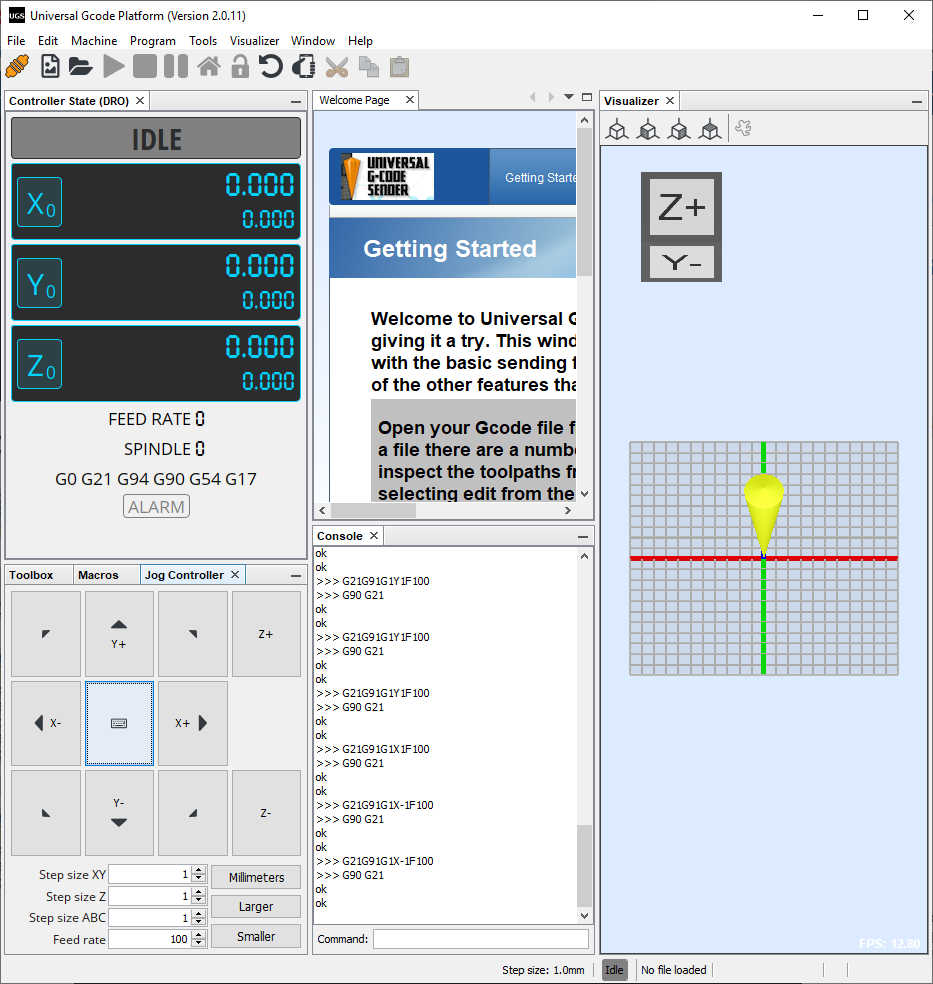
Tested with UGS
Tested with Arduino Sketch
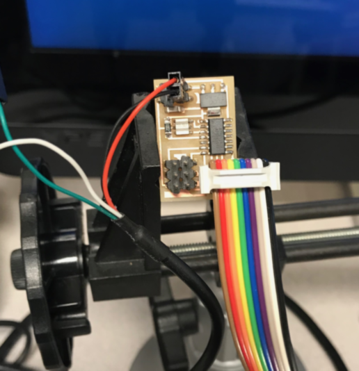
To show the path followed by the machine, I used my XY Plotter, driven by the same controller used in our machine.
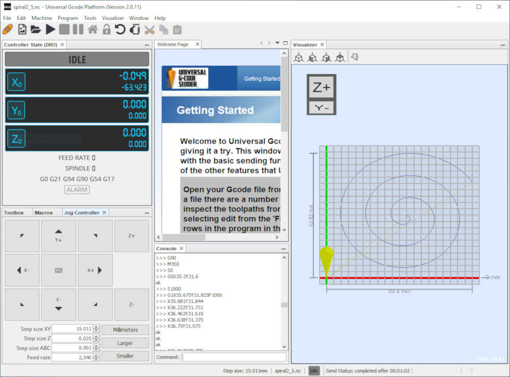
Little spiral in UGS as G-code.
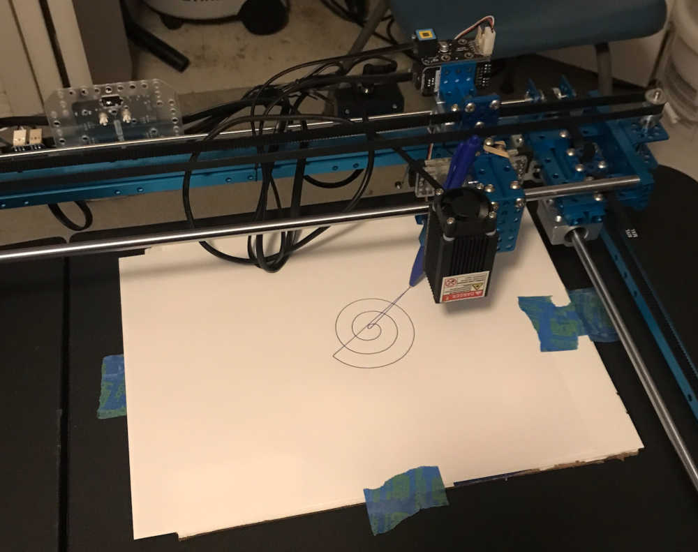
XY Plotter shows the path in ink.
This is a video of the spiral and sound.
- Mechanism and Manual Operation
Build the mechanical parts and operate it manually
Abby assembled the 3D printed stages and installed the hardware and motors; she operated it manually to ensure that the movement would be correct.
- Actuation
Actuation was performed using the Arduino Uno/CNC Shield/Stepper Motor Driver controller to drive the X and Y stepper motors. The end effector was an electomagnetic pickup fed into an amplifier and played on a speaker. The motion of the motors provided the magnetic waves necessary to make noise.
- Automation
Automation was accomplished by sending g-code to the controller using Universal G-Code Sender software. Jim made a spiral.svg file in Inkscape, resized it in Illustrator, opened the svg file in LaserGRBL and saved the nc file. Once opened in UGS, the nc file was sent to the controller and produced the desired noise by automatically driving the stepper motors. It sounded pretty cool 😎
Results
After my testing on the XY Plotter using the same CNC controller, I sent the Little_Spiral gcode to Abby and she sent uploaded it into her CNC controller. This is the result.
During the video, Abby sent the spiral2_5.nc file to the controller. The sound was generated and sent to the speaker. You need to see/hear the whole clip. At the end, Abby said, “that was the little spiral.” :)
To really appreciate the artistry of the makers, you should listen to Steppenwolf’s Magic Carpet Ride…
Grand Finale
Future Developments
This was a great learning experience in making machines that make noise. In the future this machine can be made more stable and more precise in making sounds and noises that are repeatable in loops. Spiral Development!
Abby Aresty went on to feature this design and use at Concert Sound at Oberlin College. The Vimeo video can be viewed here.
Included your original design files:
-
This is a list of our original design files discussed on this page:
-
2D Vector
-
Adobe Illustrator Scaled image of spiral spiral25.svg 1.9 Kb
-
Inkscape Original spiral made in Inkscape spiral.svg 2.6 Kb
-
G-Code Sent to controller through UGS spiral2_5.nc 6.8 Kb
This is a continuation of the Mechanical Design, Machine Design week in Fab Academy 2024
During Fab Academy 2024 I am a student of Fab Lab León with Pablo Nunez and Adrian Torres as my Remote Instructors.
This is a Group Assignment I have participated in for Fab Academy 2019 and Fab Academy 2022; I have summarized my participation in both cohorts in the documentation above. I did not work on this group assignment this year since both students at Fab Lab León are continuing students who have completed the group assignment as well as being remote students.