Fab academy 2020
CNC Machiene
CNC stands for Computer Numeric Control it is a process used in the manufacturing sector that involves the use of computers to control machine tools. Tools that can be controlled in this manner include lathes, mills, routers and grinders. The process involves creating a CAD(Computer Aided Design) file of the desired object. Then a specialized CAM (computer aided Manufacturing) software is required to convert the 3D CAD file into a set of codes which the machines can understand. CNC machining language, called G-code essentially controls all features like feed rate, coordination, location and speeds. With CNC machining, the computer can control exact positioning and velocity.
In our Fablab kochi we have full Size PRSalpha CNC.

Shopbot is a 3 axis machine the Z axis is perpendicular to the bed. The X and Y axisis are the length and the breadth of the machine respectively.To have a riggid supporting layer on the bottom of the workpiece we will place an additional piece of plywood above the bed called sacrificing layer .The sacrificing layer also protect the millig bit from damage by avoiding unwanted intereference with the metal body. It can be used to cut timber, plywood, soft aluminum etc and has a bed size of 4x8 feet

ShopBoat have a Powerfull Vacuum Clear to suck all dust that comes when we cut something


A collet is a subtype of chuck that forms a collar around an object to be held and exerts a strong clamping force on the object when it is tightened. It may be used to hold a workpiece or a tool. We are using ER25 collets, ER collets are slotted (alternately) from both ends and therefore compress onto the cutter along the whole length of the collet when tightened. This not only provides a better grip on the cutter shank but also allows some variation (typically 1mm) in shank sizes that may be used in a single collet. The smaller size collets are best used to hold cutters no more than 0.5mm below the nominal size. Collets are inserted into the covernut.

It is important to conisder safety while working with shopbot.There are chances of debris falling in eyes, and loud noise and protection for hands also should be considered.

ESTOP switch is Emergency STOP switches are used for stopping the work during emergencies there are two emergency stop switches will be there, One is ESTOP box which contains two additional switches one for Starting the spindle and the other for Reset. Ensure these ESTOP switches are in the OFF position position by rotating the RED STOP button on the DONGLE COUNTER CLOCKWISE

The process of tighting the bit and bits should be changed depending on the purpose.
Group Assignment
The group assignement for this week is explained in detail in the group page. To access the group page click here.
Individual Assingnment
For individual assignment, since i have to design something big.I have to think in a different way and if i am designing a furniture the scale of the furniture should be feasable. I started designing using fusion360. Designing a furniture in fusion360 is diferent than designing other things. The design should be parametric so that we can vary the thickness of the wood used without changing the design. This was my intial design.

I wanted to make a round table which has 3 regions.After the design is compled in fusion360, for shopbot the file should be saved as a dxf. And a small scale version should be made using laser cutting to check how it looks and how stable is the design.

After laser cutting it was hard to assemble the design because the legs should be attached from inside and it can get complicated when done with large object. And also the legs where too close so a weight in one side can cause toppling o the table. So if i felt that Since i had several other designs also in my mind i chose to build a herbal garden stand which can hold plant pots.
I have shown the designing part as a timelapse video since it is a simple design.
circular patternsA rendered version of the herbal garden. I used mahagony wood to closely resemble how it looks.
THen i scaled the design to 1/3 of its dimension and did a cut using laser cutter. and this time the cut was perfect fit and also really stable and also was aesthetically pleasing.

Cam settings
The dxf file needs to be opened by software VCarve which is exclusievly assigned for cam purposes.

Once the file is openend specify the length, width and thickness as 2040,1220 and 12 respectively.

To arrest the movement of work piece while milling we have to screw the work piece to the sacrificial layer.Holes can be placed using create vector tool and place accordingly .
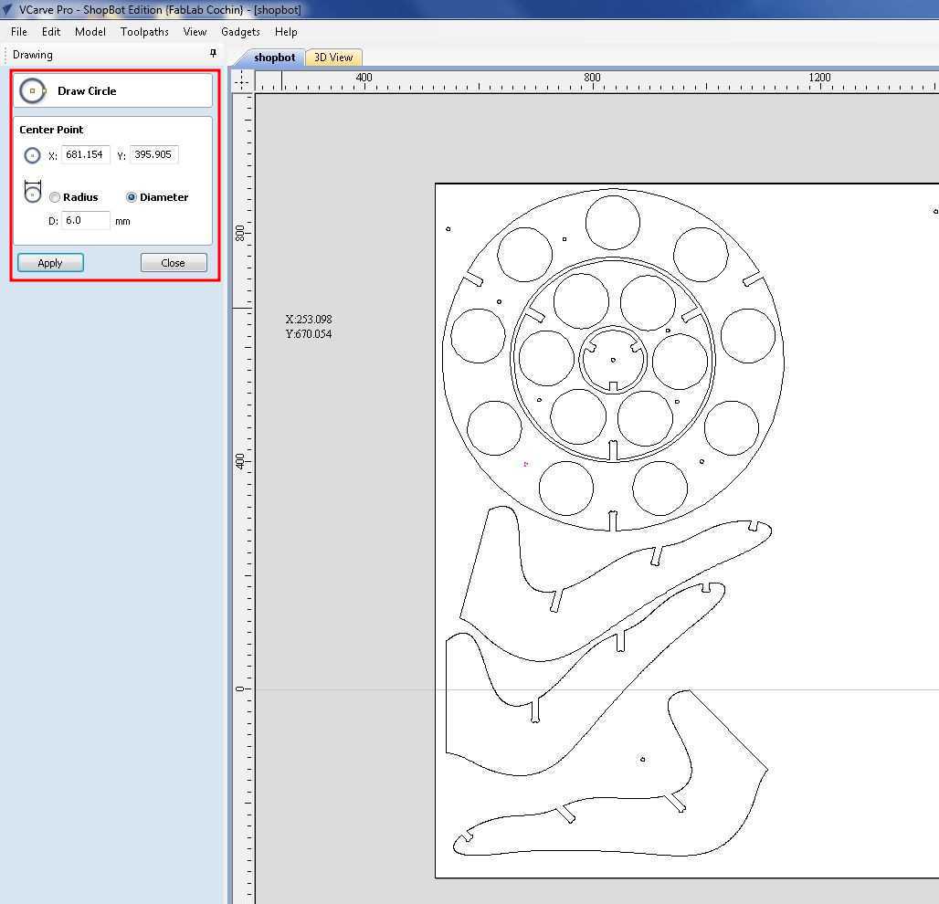
The main initial tools to use are Create vector, Join, Group..So to create drill holes clickCreate vector=>Draw circle.After enering the right diameter values. Place the drill holes on the board.
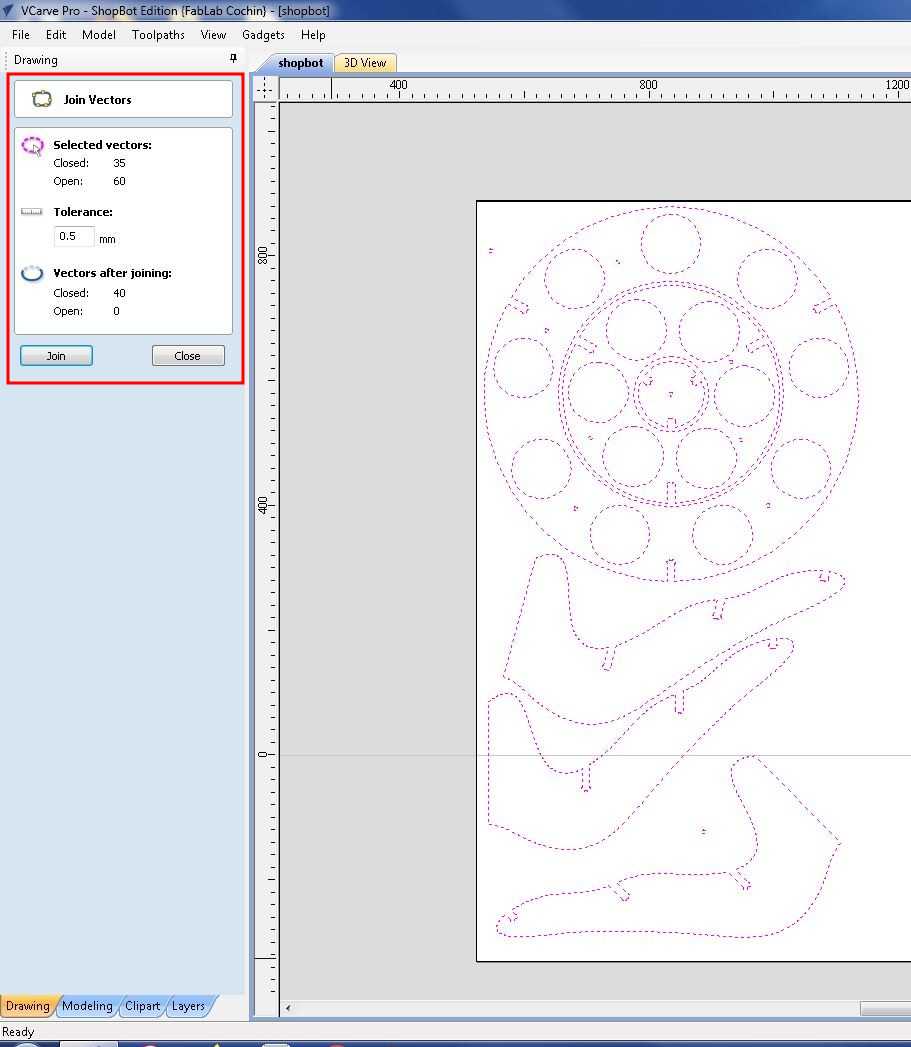
Next important step is to join closed vector as shown above. Select all the vectors and enter the joining paramters. Once the vectors are joined when you click the sketch, the complete closed vector is selected.

The next important step is to simulate the path for cutting the board, for that we have to use the tool path setup as shown above.First we have to enter the charecteristics of the milling tool. Then select the first path of drilling after that select Profileto cut the path designed file.
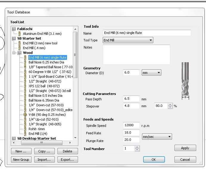
For milling wood we have to use end mill wood and i used end mill with 6mm diameter, other paramters are preset.
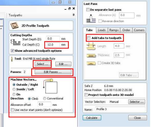
The above window is used for different paramters,first for drilling enter the depth needed to be drilled and simulate the path.For profiling we should enter where to mill-inside or outside. In my case its important to decide inside or outside since i have lot of concentric circles.
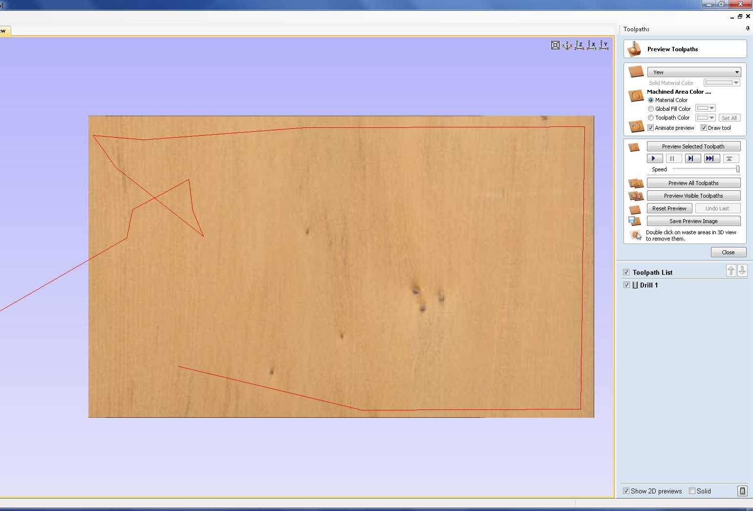
Simulated drill path. For each type of action seperate path should be created.

I grouped the vectors which needs to be drilled from outside.And gave tabs. Tabs are small connections intentionally kept keep the cut piece joined to body. So that the cutpiece doesnot hinter with milling process.Rest of the vectors where cut from inside, since inside path is not needed

Simulation of third path. I have totally three paths

As shown above each path is saved as .sbp file, which are numerical points defiend points to be milled. THe design files are attached at the bottom of this page.
The ShopBot software has a simulated DRO(Digital read out) and it has 3 main parts

For setting the origin, Jogg the endeffector to the desired origin point and click in the zero axis button .Select X and Y axis and set to zero.To set the Z axis move the endeffector tho the center of the board . For zeroing the z axis we are using the automatic methode place the zeroing plate directly under the milling bit .Connect the clip to the spindil and click the z Calibration button
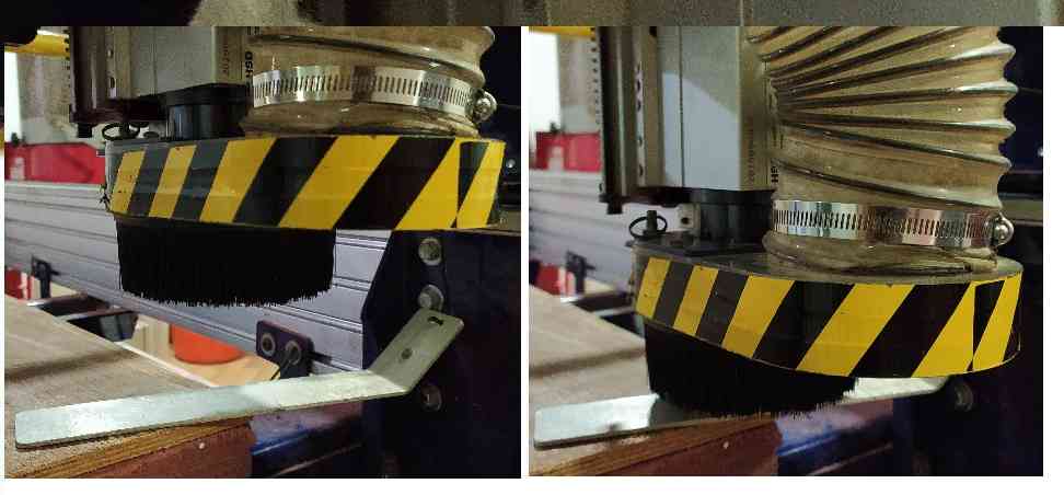
The plywood board was placed accurately on the bed and is fixed using screws so that it doesnot move while milling.

During the milling process since there was a thickness diffference at one end due to a small bulging on plywood. The milling was stoped and resumed after fixing the bulge on plywood.

The diferent milled pieces where tight to fit in due to irregularties in the thickness of the plywood. So the pieces were fit in using a mallet.

Using the orbital sander I sanded the plywood and its edges to get a smooth finish. The herbal garden was perfectly stable after the assembling process.
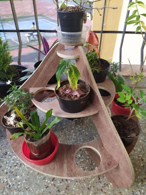
This is how it looks now. the pots fit in perfectly and plants will flourish in this tiny garden.
Download all files.Group Assignment
For group project we have to learn about the machine, and see how various parameters can be changed, and how to efficently implemnet our designs.

