Embedded programming

This Week's Objective


Program your board to do something

Group Assignment


Link for the group assignment


Individual Assignment


DATASheet

A datasheet is a document, printed or electronic that provides details about a product, like a computer, computer component, or software program. The datasheet includes information that can help in making a buying decision about a product by providing technical specifications about the product.With a computer system, a datasheet could list what a computer includes such as how many USB ports, CD or DVD drive, hard drive, processor, memory (RAM), and video card. It may also list the specific features of the motherboard in the computer. With software, a datasheet could list a program's features and the system requirements, like operating system, processor, memory, video card, and any other system requirements.

Microcontroller DataSheet

The manufacturers of microcontrollers need to explain its capabilities, electrical and mechanical characteristics, and the peripherals it has and how to interact with those along with the register interface it provides. They do that through this document called the datasheet so that everything you need to know about the microcontroller is all in one place.
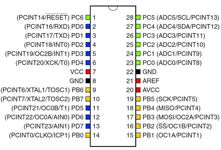
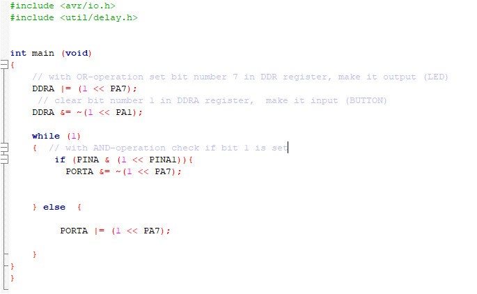
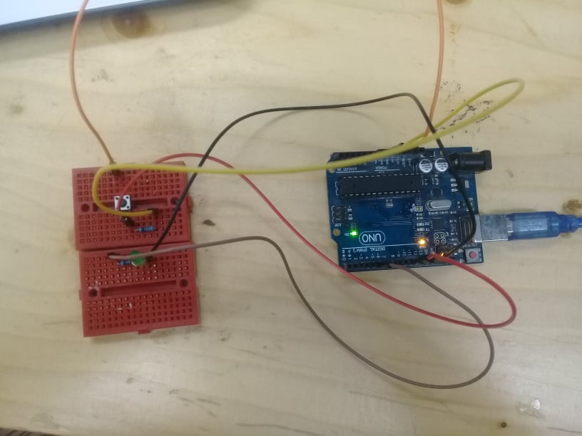
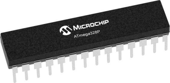
For this assignment , I will use the atmega328p, the microcontroller of the arduino board, so I will read its datasheet that you can find it here
This is some of the basic info about the microcontroller ATmega328p :
  • Number of pins: 28
  • Flash memory: 32 kb (programmable via serial interface)
  • EEPROM Data Memory: 1 kb
  • RAM Memory: 2 kb
  • 32 quick-access working registers for the ALU
  • Parallel ports: 3, with 23 I/O pins
  • Clock frequency: 16 Mhz (max. tolerated = 20 Mhz) so: 16 clock cycles per microsecond
  • 26 interruptions
  • 5 energy saving modes


  • Internal peripherals:
  • 6 x 10-bit A/D converter, analog comparator
  • 1 timer 16 bits (T1), 2 timers 8 bits(T0,T2)
  • 6 PWM channels, 1 watchdog
  • SPI, USART, TWI (=I2C)


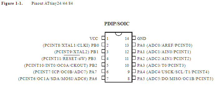
  • ATmega 328p pin-out:

    Programming the Board


    AS I said, I will use an arduino ide to do this assignment ,and to be honest, this is not the first time I have handled and programmed an arduino board, I have used it in several projects and it was very useful and simple to use, I remember that I used the code examples to understand how each sensor worked in the beginning. But now its programming has become very clear and simple for me.This is the arduino UNO board :
    I will now present the software with which I programmed the arduino board and some lines of code:
    The Arduino IDE is a cross-platform application (for Windows, macOS, Linux) that is written in functions from C and C++. It is used to write and upload programs to Arduino compatible boards, but also, with the help of 3rd party cores, other vendor development boards.
    As in most software, there are menus that allow you to perform various actions, such as creating new files, saving them and many more at the top of the software interface. There are button icons that also allow you to quickly access some of the most often performed actions. Clicking the verify button checks to make sure there are no errors in your code. Clicking upload transfers your code from your computer to your Arduino so it can run on your Arduino board.

    There is a window where you type your program, and message areas that give you information about that programAs in most software, there are menus that allow you to perform various actions, such as creating new files, saving them and many more at the top of the software interface. There are button icons that also allow you to quickly access some of the most often performed actions. Clicking the verify button checks to make sure there are no errors in your code. Clicking upload transfers your code from your computer to your Arduino so it can run on your Arduino board. There is a window where you type your program, and message areas that give you information about that program.


    Then I used the tools option to choose arduino Uno and the port my board is connected to.


    Having previously done the Hello board in the Electronic designassignment, it will be used as the board on which the program will be written too. This board has one input - button and one output - led. Here the Attiny84 MCU is used. you can find it datasheet here reading it help you find what pin to use .... Datasheets are still the best place to find the details you need to design a circuit or get one working.


    In the following code the pins of the Hello World board are used ht at correspond to the schematic of the board:
  • PIN 12 - which corresponds to the PA1 pin of the Hello Board, connected to the button.
  • PIN 6 - which corresponds to the PA7 pin of the Hello Board, connected to the LED.


  • Moving now to the code , my code allows me to put off the led,which is open ,when the button is pressed. it's the same functionality of the lamp in the fridge. you can find the code here


    const int buttonPin = 1;
    const int ledPin = 7;
    int buttonState = 0;
    
    void setup() {
    pinMode(ledPin, OUTPUT);
    pinMode(buttonPin, INPUT);
    }
    
    void loop() {
    
    buttonState = digitalRead(buttonPin);
    
    if (buttonState == HIGH) {
    digitalWrite(ledPin, LOW);
    } else {
    digitalWrite(ledPin, HIGH);
    }
    } 


    C code
    DDRB or DDRA = DATA DIRECTION REGISTER: it means the direction of this line of data it will be OUTPUT or INPUT
    PORTB or PORTA = this is the line of the output data
    PINB or PINA = this is the line of the input data
    and Letters A / B that associate with the DDR or Port or Pin are just as name.
    This is the translated versoin of the code , I use here the C code to write the same funtion you can find the code here


    in this video I've test the same code . the process is the same in the Electronic design assignment


    here with arduino I use the same code by I just change the state of led , that's mean if you push the button the led well be ON.